

Page 1

ConnectUPS
Z
WEB/SNMP Card
User’s Guide
X and BD Models
www.powerware.com
Page 2

Class B EMC Statements
FCC Part 15
NOTE This equipment has been tested and found to comply with the limits for a Class B digital
device, pursuant to part 15 of the FCC Rules. These limits are designed to provide reasonable
protection against harmful interference in a residential installation. This equipment generates, uses
and can radiate radio frequency energy and, if not installed and used in accordance with the
instructions, may cause harmful interference to radio communications. However, there is no
guarantee that interference will not occur in a particular installation. If this equipment does cause
harmful interference to radio or television reception, which can be determined by turning the
equipment off and on, the user is encouraged to try to correct the interference by one or more of
the following measures:
:
Reorient or relocate the receiving antenna.
:
Increase the separation between the equipment and the receiver.
:
Connect the equipment into an outlet on a circuit different from that to which the receiver is
connected.
:
Consult the dealer or an experienced radio/TV technician for help.
ICES-003
This Class B Interference Causing Equipment meets all requirements of the Canadian Interference
Causing Equipment Regulations ICES-003.
Cet appareil numérique de la classe B respecte toutes les exigences du Reglement sur le matériel
brouilleur du Canada.
Powerware is a registered trademark and ConnectUPS, X-Slot, BestDock, and Status@aGlance are
trademarks of Powerware Corporation.
Microsoft and Windows are registered trademarks of Microsoft Corporation. Netscape is a
trademark of Netscape Communications Corporation. HyperTerminal is a registered trademark of
Hilgraeve. Novell, and NetWare are registered trademarks of Novell, Inc. UNIX is a registered
trademark of The Open Group. Linux is a registered trademark of Linus Torvalds. OpenView is a
trademark of Hewlett-Packard Company. IBM is a registered trademark of International Business
Machines Corporation.
.
Copyright 2002 Powerware Corporation, Raleigh, NC, USA. All rights reserved. No part of this
document may be reproduced in any way without the express written approval of Powerware
Corporation.
Page 3

Requesting a Declaration of Conformity
Units that are labeled with a CE mark comply with the following harmonized standards and EU
directives:
:
Harmonized Standards: EN 50091-1-1 and EN 50091-2; IEC 950 Second Edition,
:
EU Directives: 73/23/EEC, Council Directive on equipment designed for use within certain
The EC Declaration of Conformity is available upon request for products with a CE mark. For
copies of the EC Declaration of Conformity, contact:
Powerware Corporation
Koskelontie 13
FIN-02920 Espoo
Finland
Phone: +358-9-452 661
Fax: +358-9-452 665 68
Amendments A1, A2, A3, and A4
voltage limits
93/68/EEC, Amending Directive 73/23/EEC
89/336/EEC, Council Directive relating to electromagnetic compatibility
92/31/EEC, Amending Directive 89/336/EEC relating to EMC
Page 4

Page 5

TABLE OF CONTENTS
1 Introduction 1......................................
System Application 3............................................
2 Installation 5.......................................
ConnectUPS Web/SNMP Card Front Panels 6...........................
LED Description 7............................................
Configuration 7................................................
Configuring the Card Locally 7...................................
Configuring the Card Remotely 8.................................
3 Local Configuration 9................................
Before You Start 9..............................................
Connecting the Card 9...........................................
Configuring the Card 11...........................................
Set the IP Address, Gateway Addressand MIB System Group 14............
Set Web/SNMP Card Control Group 14..............................
Set Write Access Managers 15...................................
Set Trap Receivers 15..........................................
Set IP Addresses of Primary and SecondaryDate Server 15................
UPS Event Actions 15..........................................
Set UPS Information 16.........................................
Set Superuser Name and Password 16..............................
Email Notification 16..........................................
Set Website Links 16..........................................
Back to Main Menu 16.........................................
4 Remote Configuration 17..............................
Add a Routing Condition in the Computer 17............................
Running the Web Browser 18.......................................
Setup Network Configuration 19.....................................
5 UPS Power Management 21............................
UPS Management from a Web Browser 21.............................
Viewing Status@aGlance 21.....................................
ConnectUPS MultiView Software 22................................
ConnectUPSZWeb/SNMP Card (X and BD Models) User’s Guide : Rev A www.powerware.com
i
Page 6

Table of Contents
Becoming a Superuser 22.......................................
Turning the UPS On and Off 23....................................
Forcing the UPS to Shut Down 23..................................
Planning a Scheduled UPS Shutdown and Restart 24....................
Configuring E-mail Notification 25.................................
Performing a Manual UPS Battery Test 27............................
Viewing the UPS History Logs 27..................................
UPS Management from an SNMP NMS 27.............................
Viewing UPS Monitoring Parameters 28.............................
Forcing the UPS to Shut Down 28..................................
Receiving Event Traps 28........................................
Automatic Shutdown of UPS-Protected Computers 29......................
Appendix 31........................................
DIP Switch Description 32.........................................
Jumper 1 (JP1) Settings 32.........................................
Upgrading the Card Firmware 33.....................................
Service and Support 34...........................................
Two-Year Limited Warranty (US and Canada Only) 35......................
International Limited Warranty 36....................................
ii
ConnectUPSZWeb/SNMP Card (X and BD Models) User’s Guide : Rev A www.powerware.com
Page 7

CHAPTER 1
INTRODUCTION
The ConnectUPSZWeb/SNMP Card is a network card for
your uninterruptible power system (UPS) that provides both
SNMP and HTTP compatibility. You can install the card in any
Powerware
The ConnectUPS Web/SNMP Card is available in two models:
the ConnectUPS-X for X-Slot UPSs and the ConnectUPS-BD
for UPSs with a BestDock slot. Both models can connect to a
twisted-pair Ethernet (10/100BaseT) network using an RJ-45
connector.
The ConnectUPS-X has a built-in switching hub that allows
three additional network devices to be connected to the
network without the requirement of additional network drops.
With the ConnectUPS Web/SNMP Card, you can monitor the
UPS several different ways:
using a Web browser such as Microsoft
:
or NetscapeZto monitor and manage the connected UPS.
using your Internet-ready cell phone or PDA (personal
:
digital assistant).
SNMP-compatible network management software
:
(user-supplied) monitors the UPS in a method similar to
that of other network devices.
The card also supports remote monitoring and shutdown from
UPS-protected computer systems. NetWatch client software for
use with a ConnectUPS Web/SNMP Card is supplied on the
Powerware Software Suite CD or on the Web at
www.powerware.com. Client software is available for
Microsoft Windows
NetWare9and various versions of UNIX9including Linux
These programs communicate through TCP/IP with the
ConnectUPS Web/SNMP Card and automatically shutdown the
protected system during extended power outages.
9
UPS that has an X-SlotZor a BestDockZslot.
9
Internet Explorer
9
95/98/Me/NT/2000/XP, Novell
,
9
9
.
ConnectUPSZWeb/SNMP Card (X and BD Models) User’s Guide : Rev A www.powerware.com
1
Page 8

Introduction
In addition, the ConnectUPS Web/SNMP Card has the
following features:
Hot-swappable feature simplifies installation by allowing
:
you to install the card safely without powering down the
critical UPS load.
Configuration from serial port, Telnet, or HTTP Web
:
browser.
Management from HTTP Web browser, Internet-ready cell
:
phone or PDA, or SNMP management software.
E-mail notification of changes in the UPS status through
:
SMTP (simple mail transport protocol) via e-mail client
software, a PCS (personal communication services) phone,
or alphanumeric pager.
Supports Powerware (XUPS.MIB) and RFC-1628 Standard
:
UPS (STDUPSV1.MIB) management information bases.
Firmware upgradable from a Microsoft Windows utility via
:
a network connection.
Scheduling function to control UPS shutdowns and
:
startups.
History log files (data and events) for recording power
:
problems.
UPS status information available to registered NetWatch
:
clients for automatic shutdown of Microsoft Windows
95/98/Me/NT/2000/XP, Novell NetWare, and UNIX
(including Linux).
With a special Status@aGlanceZpage, a color-coded
:
background on your Web browser provides quick visibility
of the UPS status.
Multiple ConnectUPS Web/SNMP Cards can be monitored
:
simply using free ConnectUPS MultiView software.
2
ConnectUPSZWeb/SNMP Card (X and BD Models) User’s Guide : Rev A www.powerware.com
Page 9
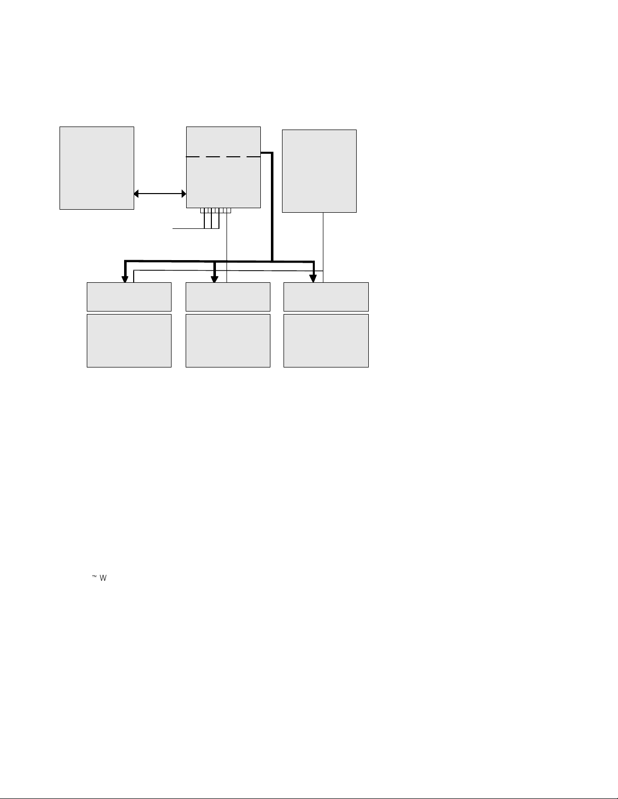
System Application
The following diagram shows how the ConnectUPS
Web/SNMP Card can be used in a network application.
Management
Station or
Terminal
RS-232
UPS
ConnectUPS-X
or
ConnectUPS-BD
Introduction
NMS Station
or
Web Browser
Additional network connections
with ConnectUPS-X
Power Line
NetWatch Client NetWatch Client NetWatch Client
Microsoft Windows
95/98/Me/NT/2000/XP
UNIX/Linux
NetWare
Figure 1. ConnectUPSWeb/SNMP Card SystemApplication Diagram
Ethernet
ConnectUPSZWeb/SNMP Card (X and BD Models) User’s Guide : Rev A www.powerware.com
3
Page 10

Introduction
4
ConnectUPSZWeb/SNMP Card (X and BD Models) User’s Guide : Rev A www.powerware.com
Page 11
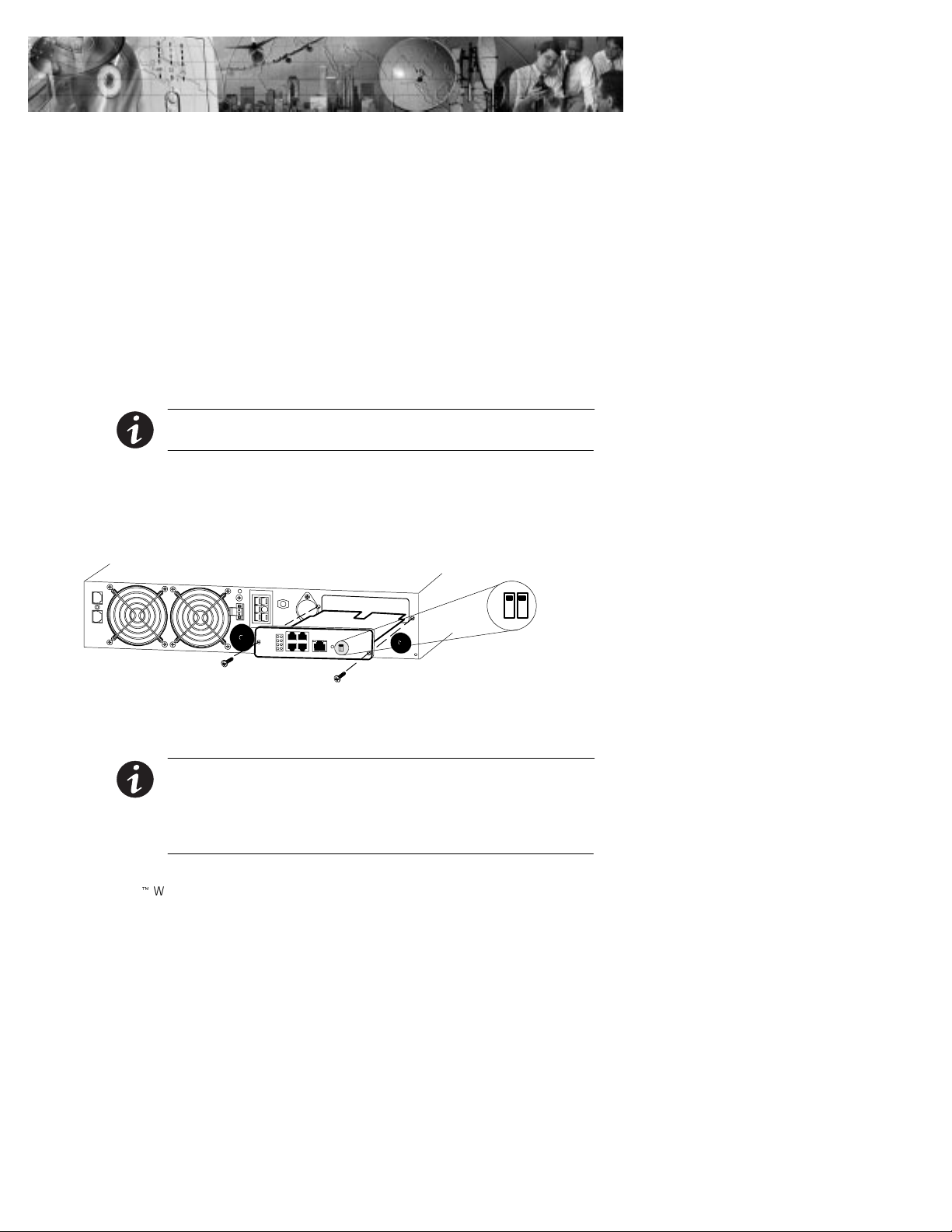
CHAPTER 2
INSTALLATION
With the hot-swappable feature, the ConnectUPS Web/SNMP
Card can be installed easily without turning off the UPS or
disconnecting the load.
To install the ConnectUPS Web/SNMP Card, perform the
following steps:
1. Verify that both DIP switches on the card are set to
0 (off) position.
the
2. Remove the X-Slot or BestDock cover on the UPS rear
panel. Retain the screws.
NOTE If there is another card already installed with an attached
communication cable, disconnect the cable and then remove the card.
3. To prevent electrostatic discharge (ESD), place one
hand on a metal surface such as the UPS rear panel.
Slide the ConnectUPS Web/SNMP Card into the open
slot and secure with the screws removed in Step 2.
0
1
4. Connect an active 10/100BaseT cable to the Uplink
Ethernet connector on the ConnectUPS-X or to the
network connector on the ConnectUPS-BD.
NOTE Three additional 10/100 Mb Ethernet connectors are available on
the ConnectUPS-X and are served by an internal switching hub. If you
frequently move devices between these connectors or make configuration
changes, it may be necessary to clear the cache by pressing the Reset
button on the card front panel.
ConnectUPSZWeb/SNMP Card (X and BD Models) User’s Guide : Rev A www.powerware.com
5
Page 12
Installation
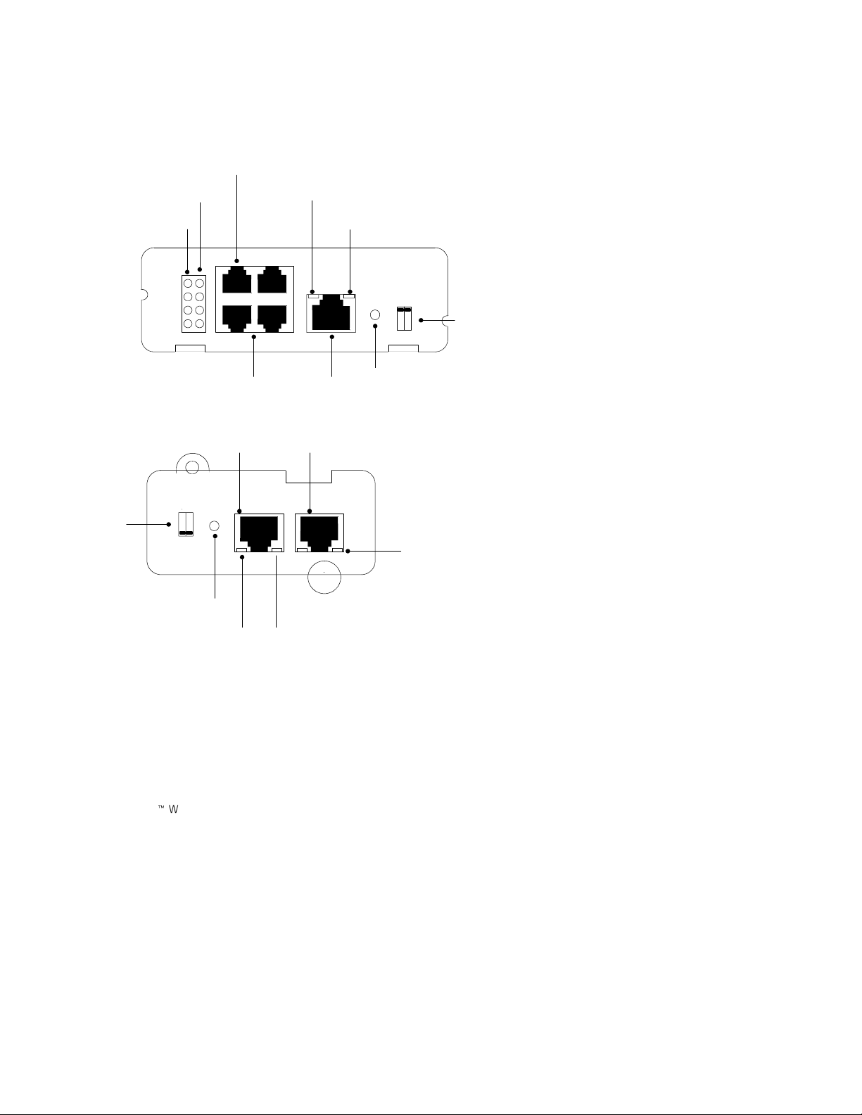
ConnectUPS Web/SNMP Card Front Panels
The card panel details are shown in Figure 2 and Figure 3.
Uplink Ethernet Connector
10 Mb Network LEDs (yellow)
100 Mb Network LEDs (green)
Additional Ethernet Connectors
Figure 2. ConnectUPS-XPanel Details
On
DIP Switch
Off
21
Power LED (green)
COM Port
COM Port
Ethernet Connector
COM NETWORK
Status LED (yellow)
Off
On
12
Reset Button
100 Mb Network LED
(green)
DIP Switch
Reset Button
Status LED (yellow)
6
ConnectUPSZWeb/SNMP Card (X and BD Models) User’s Guide : Rev A www.powerware.com
10 Mb Network LED (yellow)
Page 13

LED Description
The functions of the ConnectUPS Web/SNMP Card are
indicated by the Status and either the 10 Mb or 100 Mb LEDs,
as listed in Table 1.
Table 1. LED Definitions
Status LED 10 Mb or
Flickering On/Flickering Normal operation with Ethernet traffic
Configuration
You must configure the ConnectUPS Web/SNMP Card before
you can use it. There are two ways to configure the card:
locally through the serial communication port
:
remotely using a Web browser or Telnet utility
:
Installation
Card Function Description
100 Mb LED
On On ConnectUPS Web/SNMP Card error
Off Off UPS power low (no power to the
ConnectUPS Web/SNMP Card)
Flashing Flashing No connection to UPS (alternate flashing as
the ConnectUPS Web/SNMP Card restarts)
Configuring the Card Locally
The card has a configuration program that you can access by
using the supplied serial cable to connect the card to a terminal
or a computer with a terminal emulation program.
If you choose to configure your card locally, see “Local
Configuration” on page 9.
ConnectUPSZWeb/SNMP Card (X and BD Models) User’s Guide : Rev A www.powerware.com
7
Page 14

Installation
Configuring the Card Remotely
You can configure the card remotely through a network using
a Web browser or Telnet utility.
NOTE Security-related parameters and some hardware parameters cannot
be configured from a Web browser, but can be changed from the Telnet
utility.
If you choose to configure your card remotely, see “Remote
Configuration” on page 17.
8
ConnectUPSZWeb/SNMP Card (X and BD Models) User’s Guide : Rev A www.powerware.com
Page 15

CHAPTER 3
LOCAL CONFIGURATION
Use the following procedure to access the card’s configuration
program through a serial port.
Before You Start
To use the configuration program for the card, you need:
The serial cable included with the card.
:
A terminal with a serial communication port, or a computer
:
with a terminal emulation program such as HyperTerminal
The serial line should be set to 9600 baud, No parity, 8 data
bits, 1 stop bit, and no flow control.
Connecting the Card
To connect the card to the terminal or computer and start the
configuration program:
1. Plug the serial cable into the COM port on the
ConnectUPS Web/SNMP Card.
2. Plug the other end of the serial cable into the TTY
port on the terminal or the COM port on your
computer.
9
.
ConnectUPS
Web/SNMP Card
To TTY port on terminal
or COM port on computer
Serial Cable
Figure 4. Cable Connection from Serial Port
ConnectUPSZWeb/SNMP Card (X and BD Models) User’s Guide : Rev A www.powerware.com
9
Page 16

Local Configuration
3. Open your terminal emulation program such as
HyperTerminal and select the appropriate serial
connection (such as COM1).
The serial line should be set to 9600 baud, No parity,
8 data bits, 1 stop bit, and no flow control.
4. Verify that the UPS is turned on.
5. After a few seconds, press [Enter]. The Password
screen appears (see Figure 5).
If the screen does not appear, press [Enter] again.
If you still do not see the Password screen, check the
following conditions:
Verify the serial line is set to 9600 baud, No parity,
:
8 data bits, 1 stop bit, and no flow control.
If the serial line settings are correct, check the
:
cabling to verify all connections are secure.
Verify that your terminal program is on the correct
:
communication port for the serial connection.
Verify that the ConnectUPS Web/SNMP Card has
:
power (one or more LEDs on the card should be
illuminated). The UPS should be turned on.
6. Type your password (the default password is admin)
and press [Enter]. The Main Menu screen appears.
+===================================================================
| [ ConnectUPS Web/SNMP Card Configuration Utility ]
+===================================================================
Enter Password: *****
+===================================================================
| [ ConnectUPS Web/SNMP Card Configuration Utility ]
+===================================================================
1. Web/SNMP Card Settings
2. Reset Configuration to default
3. Restart Web/SNMP Card
4. UPS Pass-Through
0. Exit
Please Enter Your Choice =>_
10
Figure 5. ConnectUPSWeb/SNMP Card Main Menu Screen
ConnectUPSZWeb/SNMP Card (X and BD Models) User’s Guide : Rev A www.powerware.com
Page 17

Local Configuration
Configuring the Card
To configure the card:
1. Type
+===================================================================
| [ ConnectUPS Web/SNMP Card Configuration Utility ]
+===================================================================
1. Web/SNMP Card Settings
2. Reset Configuration to default
3. Restart Web/SNMP Card
4. UPS Pass-Through
0. Exit
Please Enter Your Choice =>1
+===================================================================
| [ ConnectUPS Web/SNMP Card Configuration Utility ]
+===================================================================
1. Set the IP Address, Gateway Address and MIB System Group
2. Set Web/SNMP Card Control Group
3. Set Write Access Managers
4. Set Trap Receivers
5. Set IP Addresses of Primary and Secondary Date Server
6. UPS Event Actions
7. Set UPS Information
8. Set Superuser Name and Password
9. Email Notification
10. Set Website Links
0. Back to Main Menu
1 to enter the Web/SNMP Card Settings screen
(see Figure 6).
Please Enter Your Choice =>_
Figure 6. Web/SNMP Card Settings Screen
2. Type 1 to enter the Set the IP Address, Gateway
Address and MIB System Group menu. Enter the
appropriate settings for your network (see page 14).
ConnectUPSZWeb/SNMP Card (X and BD Models) User’s Guide : Rev A www.powerware.com
11
Page 18

Local Configuration
NOTE The ConnectUPS Web/SNMP Card may take up to two minutes to
establish communication with the UPS. Please wait before attempting
communication with the card from a Web browser or network management
system (NMS).
NOTE
can use a Telnet utility to adjust any of the configuration settings. The
menus are identical to those seen during serial configuration and are
password-protected for Superuser access only.
3. Change any other options as needed for your
particular configuration by typing the corresponding
number shown in the menu (
2 through 10). Each
setting is described in the following sections.
4. Type
5. Type
0 to return to the Main Menu.
0 to exit the ConnectUPS Web/SNMP Card
configuration. The ConnectUPS Web/SNMP Card
automatically saves all settings after exiting the
configuration function (see Figure 7).
Telnet Operation – Once the card isreachable on the network, you
12
ConnectUPSZWeb/SNMP Card (X and BD Models) User’s Guide : Rev A www.powerware.com
Page 19

Local Configuration
+===================================================================
| [ ConnectUPS Web/SNMP Card Configuration Utility ]
+===================================================================
1. Set the IP Address, Gateway Address and MIB System Group
2. Set Web/SNMP Card Control Group
3. Set Write Access Managers
4. Set Trap Receivers
5. Set IP Addresses of Primary and Secondary Date Server
6. UPS Event Actions
7. Set UPS information
8. Set Superuser Name and Password
9. Email Notification
10. Set Website Links
0. Back to Main Menu
Please Enter Your Choice =>0
+===================================================================
| [ ConnectUPS Web/SNMP Card Configuration Utility ]
+===================================================================
1. Web/SNMP Card Settings
2. Reset Configuration to default
3. Restart Web/SNMP Card
4. UPS Pass-Through
0. Exit
Please Enter Your Choice =>0
Figure 7. Exiting the Configuration Program
ConnectUPSZWeb/SNMP Card (X and BD Models) User’s Guide : Rev A www.powerware.com
13
Page 20

Local Configuration
Set the IP Address, Gateway Address and MIB System
Group
Use this function (option 1) to set the IP address, the gateway
address, or the management information base (MIB)
parameters of the card, as listed in Table 2.
Table 2. Parameters with Examples
No. Function Description Example
1 IP Address IP address of the card 192.72.173.188
2 Gateway
Address
3 Network Mask Subnet mask setting 255.255.255.0
4 sysContact System contact string of MIB (up to 127
5 sysName System name parameter for MIB (up to 127
6 sysLocation System location parameter for MIB (up to
Default IP address of the network gateway 192.72.173.254
Powerware
characters)
ConnectUPS Web/SNMP
characters)
127 characters)
Card
TEST LAB
14
Set Web/SNMP Card Control Group
For those users who intend to use BOOTP/DHCP, Telnet, or
secure HTTP in order to configure, control, update, or manage
the card, certain control parameters must be enabled or
disabled. Use this function to modify those parameters
(option
NOTE To prevent unauthorized viewing of the Web pages presented by
the ConnectUPS Web/SNMP Card, use this function to enable HTTP
Security Control.
NOTE To obtain an IP address using BOOTP/DHCP (instead of serial
configuration), set DIP Switch 2 on the front panelto the ON position (OFF
is the default).
ConnectUPSZWeb/SNMP Card (X and BD Models) User’s Guide : Rev A www.powerware.com
2).
Page 21

Local Configuration
Set Write Access Managers
For those users who intend to use an SNMP-compatible NMS
to manage the ConnectUPS Web/SNMP Card, the IP address of
the management station must be added to the list on the
ConnectUPS Web/SNMP Card in order to receive read (get) or
write (set) access rights. Community strings may be different
for read or write access. Use this function to add or delete the
IP address of the management station (option
3).
Set Trap Receivers
For those users who intend to use an SNMP-compatible NMS
to manage the ConnectUPS Web/SNMP Card, the IP address of
the machine intended to be the trap receiver must be added to
the list on the ConnectUPS Web/SNMP Card. Use this function
to add or delete the IP address of the trap receivers (option
4).
This information is accessible via the HTTP interface for easy
modification after the card is on the network.
Set IP Addresses of Primary and Secondary Date Server
Use this function to set the IP addresses of the primary and
secondary date servers (option
accessible via the HTTP interface for easy modification after
the card is on the network.
Computer systems with the ConnectUPS Web/SNMP
Card-compatible NetWatch client software are periodically
monitored by the ConnectUPS Web/SNMP Card to maintain a
consistent date and time with your network. The computers’IP
address must be listed as the Primary or Secondary Date
Server.
5). This information is
UPS Event Actions
Use this function to configure actions that the ConnectUPS
Web/SNMP Card performs during AC Fail and Low Battery
events (option
interface for easy modification after the card is on the network.
ConnectUPSZWeb/SNMP Card (X and BD Models) User’s Guide : Rev A www.powerware.com
6). This information is accessible via the HTTP
15
Page 22

Local Configuration
Set UPS Information
Use this function to enter additional information about the
UPS including date of installation and date of last battery
replacement (option
to the shutdown and restart of the UPS via this function. This
information is accessible via the HTTP interface for easy
modification after the card is on the network.
Set Superuser Name and Password
Use this function to set or change the user name and password
of the administrator who will use a Web browser to configure
the ConnectUPS Web/SNMP Card (option
Email Notification
Use this function to inform selected e-mail accounts of events
and changes in the status as they occur in the UPS or to
provide a daily status message at a predetermined time
(option
interface for easy modification after the card is on the network.
7). In addition, set timing values relating
8).
9). This information is accessible via the HTTP
16
Set Website Links
Use this function to set links to different Web sites (option 10).
Links appear on the Web pages of the ConnectUPS Web/SNMP
Card. This information is accessible via the HTTP interface for
easy modification after the card is on the network.
Back to Main Menu
Type 0 to return to the Main Menu screen (see Figure 7 on
page 13).
ConnectUPSZWeb/SNMP Card (X and BD Models) User’s Guide : Rev A www.powerware.com
Page 23

CHAPTER 4
REMOTE CONFIGURATION
Use the following procedure to access the card’s configuration
program through a Web browser.
NOTE Verify that an active 10/100BaseT cable is connected to the card’s
network connector (the Uplink Ethernet connectoron the ConnectUPS-X).
Add a Routing Condition in the Computer
If the IP address of the computer is on the same network with
the ConnectUPS Web/SNMP Card, you may just run the Web
browser directly.
If the IP address of the computer is not on the same network
with the ConnectUPS Web/SNMP Card (only required while
configuring the card), you can use the Add Routing command.
1. Turn on the computer and set up the TCP/IP protocol
if needed.
2. Enter the following command to add a routing
condition:
Route add 192.168.7.18 192.72.173.20
where 192.168.7.18 is the default IP address of the
card and 192.72.173.20 is an example IP address for
the computer.
NOTE Refer to your operating system documentation for additional details
on how to add a routing condition.
ConnectUPSZWeb/SNMP Card (X and BD Models) User’s Guide : Rev A www.powerware.com
17
Page 24

Remote Configuration
Running the Web Browser
Locate a computer (PC, host, or server) that has a Web
browser (Internet Explorer or Netscape recommended) and is
connected to a network.
1. Run the Web browser and connect to the ConnectUPS
Web/SNMP Card IP address (the default is
192.168.7.18).
2. ThehomepageoftheConnectUPSWeb/SNMPCard
appears (see Figure 8).
18
Figure 8. ConnectUPSWeb/SNMP Card Home Page
ConnectUPSZWeb/SNMP Card (X and BD Models) User’s Guide : Rev A www.powerware.com
Page 25

Setup Network Configuration
1. Select Configuration from the menu at the top of the
home page, then
the ConnectUPS Web/SNMP Card parameters (see
Figure 9).
2. Click
Become Superuser and log in with the Username
and Password (the default user name and password is
admin).
Remote Configuration
Web/SNMP Card Configuration to set
Figure 9. ConnectUPSWeb/SNMP Card Configuration Page
ConnectUPSZWeb/SNMP Card (X and BD Models) User’s Guide : Rev A www.powerware.com
19
Page 26

Remote Configuration
NOTE If you changed the IP address in Step 3, you must restart the
browser using the new IP address (see page 18) to restore communication
with the ConnectUPS Web/SNMP Card. Repeat Steps 1 and 2 to continue
the configuration.
The ConnectUPS Web/SNMP Card is now configured for
operation on your network. Refer to the remainder of this
user’s guide and the online help for detailed information about
each menu selection.
3. Select and edit the ConnectUPS Web/SNMP Card IP
Address
4. Select and edit the
5. Select and edit the
6. Select
.
Gateway Address for the network.
Subnet Mask of the network.
Set Values to save the new settings.
7. Select Date and Time from the menu at the top of the
page.
8. Enter the appropriate date and time information in
the specified format.
9. Select
Set Values to save the date and time settings.
20
ConnectUPSZWeb/SNMP Card (X and BD Models) User’s Guide : Rev A www.powerware.com
Page 27

CHAPTER 5
UPS POWER MANAGEMENT
You can manage the UPS from a Web browser or from an
SNMP network management system.
UPS Management from a Web Browser
When using a Web browser to access the ConnectUPS
Web/SNMP Card, the majority of UPS-related information is
available by selecting any of the following menu options:
Identification
:
UPS Monitoring
:
UPS History
:
Configuration
:
Control
:
Registered Clients
:
Help
:
Each menu and submenu selection has online help available.
Viewing Status@aGlance
Status@aGlance is a page that provides a simple, intuitive way
to view UPS status information and is accessed through a link
on the UPS Monitoring > UPS Status page. It changes the
background color of the page to reflect the UPS status:
green indicates normal UPS operation
:
yellow indicates the UPS is responding to a problem (the
:
UPS is on battery during a power outage; the UPS has one
or more alarms present; or the UPS has been bypassed)
red indicates a low battery condition and shutdown is
:
imminent
black indicates a loss of communication between the UPS
:
and the ConnectUPS Web/SNMP Card
ConnectUPSZWeb/SNMP Card (X and BD Models) User’s Guide: Rev A www.powerware.com
21
Page 28

UPS Power Management
If you leave the browser pointed to this page, it automatically
updates when new UPS information is available. To return to
the UPS Status page, point and click the mouse pointer
anywhere within the colored background area.
ConnectUPS MultiView Software
The Status@aGlance pages of several ConnectUPS Web/SNMP
Cards may be monitored simultaneously by installing the
ConnectUPS MultiView software on a PC with Microsoft
Windows 95/98/Me/NT/2000/XP.
The software is included on the CD-ROM supplied with the
ConnectUPS Web/SNMP Card or it can be downloaded from
the ConnectUPS Web/SNMP Card Web page (the
ConnectUPS MultiView
the UPS Monitoring page).
The ConnectUPS MultiView software works in tandem with
Internet Explorer to discover and display multiple browser
windows, each representing a different ConnectUPS
Web/SNMP Card. You also have the flexibility to pick other
Web pages as presented by the ConnectUPS Web/SNMP Card
during configuration.
Download
link on the Identification page or on
22
Becoming a Superuser
Several menus allow UPS and ConnectUPS Web/SNMP Card
parameters to be modified by the user. However, many of these
are password-protected for the Superuser. To become a
Superuser, you must log in with a user name and provide a
password. Both are configurable by serial or Telnet connection.
The default user name and password is admin.
NOTE Once you have become a Superuser, it is important to completely
exit the browser if you wish to set the security levelback to the standard
read-only level.
ConnectUPSZWeb/SNMP Card (X and BD Models) User’s Guide: Rev A www.powerware.com
Page 29

UPS Power Management
Turning the UPS On and Off
The ConnectUPS Web/SNMP Card supports the ability to
remotely turn off the UPS and its supported load. It also
supports the ability to reboot the UPS (cycling output power
off and then back on), as well as the ability to schedule
shutdowns and startups on a predetermined basis.
Selecting
Control from the menu at the top of the home page
provides a page that allows the Superuser to turn off the UPS.
In addition, you may initiate a battery test and enable or
disable any scheduled shutdowns or startups as specified in the
UPS shutdown schedule table (accessed from the
Configuration menu).
CAUTION
: Selecting Turn UPS Off turns off the output of the UPS. Any equipment
powered by the UPS shuts down. Prepare theprotected equipment for
the shutdown.
: If you select Turn UPS Off with Load Segment to Restart following
the Return of AC Power
the UPS after the shutdown occurs.
set to NO, you will haveto manually restart
Forcing the UPS to Shut Down
1. Select Configuration from the menu at the top of the
home page, then
2. Log in as a Superuser.
3. Select
4. Verify
UPS Shutdown and Restart Settings.
Load Segment to Turn Off following OS Shutdown is
YES.
set to
5. Set the appropriate
following the start of the Client’s OS Shutdown
to ensure that any NetWatch clients and their
respective operating systems have enough time to
complete their shutdown. The default is 180 seconds,
but you may wish to increase or decrease this value as
appropriate for your system.
ConnectUPSZWeb/SNMP Card (X and BD Models) User’s Guide: Rev A www.powerware.com
UPS Event Actions.
Delay Before Segment Turns Off
in seconds
23
Page 30

UPS Power Management
6. To turn off the UPS and have it stay off (requiring
7. After choosing the desired values, select
8. Select
9. To initiate the shutdown sequence, select
local interaction to turn it back on), change
Segment to Restart following the return of AC Line
Load
to NO.
If you want to effectively reboot the UPS and the
associated load, then set
following the return of AC Line
Segment Restart
to a valid delay value to allow the UPS
Load Segment to Restart
to YES and set Delay Before
to restart after the specified delay.
Set Values to
update the card with the new information.
Control from the ConnectUPS Web/SNMP Card
menuatthetopofthehomepageandselect
Segment “ALL”
“NUMBER(S)”. Then select Turn UPS Off.
or the appropriate load segment
Load
Set Values
which instructs the ConnectUPS Web/SNMP Card to
send the appropriate information to the UPS and any
clients running the NetWatch client software.
24
Planning a Scheduled UPS Shutdown and Restart
You may use the ConnectUPS Web/SNMP Card to schedule
the day of the week and time of a shutdown and a startup. The
ability to schedule shutdowns and startups is UPS dependent
(consult your UPS documentation for more information).
1. Select
2. Login as a Superuser.
3. You may configure up to seven event pairs. Enter the
4. Click
5. Once the values are set, select
ConnectUPSZWeb/SNMP Card (X and BD Models) User’s Guide: Rev A www.powerware.com
Configuration from the menu at the top of the
home page, then
upcoming
needed, the
UPS Shutdown Schedule.
Shutdown Day and Shutdown Time,andif
Restart Day and Restart Time. Times are in
24-hour format based on the date and time set within
the ConnectUPS Web/SNMP Card.
Set Values to update the card.
Control from the menu
at the top of the home page.
Page 31

UPS Power Management
6. Then select Enable UPS Shutdown Schedule, followed by
Set Values to start the process. Any shutdown/restart
events repeat until you change the table or select
Disable UPS Shutdown Schedule.
NOTE Before scheduling any shutdowns or startups, you must configure
the date and time within the ConnectUPS Web/SNMP Card.
Configuring E-mail Notification
You may use the ConnectUPS Web/SNMP Card to inform
selected e-mail accounts of events and changes in status as
they occur in the UPS or to provide a daily status message at a
predetermined time.
1. Select
2. Become a Superuser and then enter the IP address or
3. If you entered a host name for the
4. To receive a daily status report, enter the time of day
5. Enter the
6. Select
7. Test your settings by pressing the
The ConnectUPS Web/SNMP Card uses the Identification
Information field data and the card’s IP address to create the
sender’s e-mail address (default example:
UPS.Web.Card@192.168.7.18).
You can change the Identification Information field to a more
recognizable sender user name by accessing the Identification
Configuration from the menu at the top of the
home page, then
Email Notification.
Hostname of an SMTP mail server that will be used to
send the e-mail messages.
Mail Server,you
must enter the IP address of your network DNS Server
DNS Address block.
in the
to send the e-mail (in 24-hour format).
Mail Account, Description, Mail Type, Event
,andEvent Type for each recipient. The Mail
Level
Account must be a valid e-mail address. Refer to the
online help file for more details on each of these
fields.
Set Values to save your changes.
Send Test button.
ConnectUPSZWeb/SNMP Card (X and BD Models) User’s Guide: Rev A www.powerware.com
25
Page 32

UPS Power Management
page with your browser. This is especially helpful if you have
more than one ConnectUPS Web/SNMP Card and intend to
receive e-mails at a central location.
If your SMTP server requires a qualified domain name instead
of an IP address or requires a qualified user name in the
sender’s email address, additional configuration items are
available with a serial or Telnet connection (see Chapter 3,
“Local Configuration” on page 9). SMTP configuration options
areavailablethrough
Settings menu. Under most circumstances, changes are not
required for these options.
NOTE To completely clear the contents of any configuration item, enter a
tilda (~) and press the Enter key.
: SMTP Port Number – SMTP server access is typically gained
via port 25. For installations where a different port number
is used, configure the port number using this option.
Substitute Domain Name for Sender’s Email Address – The default
:
domain name for the sender’s e-mail address is the
ConnectUPS Web/SNMP Card’s IP address. You can enter a
qualified domain name with this option.
Optional SMTP Username – The ConnectUPS Web/SNMP
:
Card’s Identification Information field data is used as the
user name for the SMTP server as well as in the sender’s
e-mail address. Use this option to configure a qualified user
name.
Note that the text used in the Identification Information
field remains unaffected; this text is also used to display
additional information when browsing the card.
Optional SMTP Password – Under certain circumstances, a
:
password may be required to obtain access to a SMTP
server. If your server requires a password, enter it here.
When changing any e-mail configuration items, it is strongly
recommended to use the
changes. Any e-mail errors are logged in the ConnectUPS
Web/SNMP Card Event Log. Review the Event Log within a
few minutes of testing the e-mail to see if any errors are
logged.
Email Notification on the Web/SNMP Card
Send Test function to test your
26
ConnectUPSZWeb/SNMP Card (X and BD Models) User’s Guide: Rev A www.powerware.com
Page 33

UPS Power Management
Performing a Manual UPS Battery Test
You can use the ConnectUPS Web/SNMP Card to manually
perform a UPS battery test. The ability to test the UPS is model
dependent (consult your UPS documentation for more
information).
1. To manually start a battery test on a specific UPS,
Control from the menu at the top of the home
select
page.
2. Become a Superuser and then select
followed by
Set Values to start the process.
Initiate Battery Test,
Viewing the UPS History Logs
Selecting UPS History from the menu at the top of the home
page allows you to choose the current
Event Log
. The data log provides numerical data logged once a
minute from the UPS. The event log contains text messages
regarding the status of the UPS and the ConnectUPS
Web/SNMP Card. Past data and event logs are also accessible,
as well as a data log applet that displays the data in a graphical
format.
UPS Data Log and UPS
UPS Management from an SNMP NMS
To access the ConnectUPS Web/SNMP Card via SNMP, use the
following steps:
1. Use these Community strings:
GET Community string: public
SET Community string: private
By default, the ConnectUPS Web/SNMP Card’s Write
Access Managers table is configured for read-only
SNMP access to any NMS with a public community
string. An NMS with a private community string has
read/write SNMP access.
NOTE For security, it is recommended to change the Write Access
Managers table using specific IPaddresses and nonstandard community
strings.
ConnectUPSZWeb/SNMP Card (X and BD Models) User’s Guide: Rev A www.powerware.com
27
Page 34

UPS Power Management
2. The xups.mib and stdupsv1.mib files (on the supplied
3. Using the Facilities provided by the SNMP
Viewing UPS Monitoring Parameters
The ConnectUPS Web/SNMP Card supports several MIB
groups that separate specific UPS parameters into related areas.
ThegroupsusedintheMIBforthecardinclude:
Ident
:
Battery
:
Input
:
Output
:
Config
:
Control
:
Test
:
Alarms
:
Bypass
:
Traps
:
CD-ROM) contain the MIB for the ConnectUPS
Web/SNMP Card. Add these files to the MIB database
of your SNMP management software (such as HP
9
OpenViewZIBM
,
Director, and Sun NetManager).
management software, you can access the individual
MIB objects. Refer to the MIB files on the supplied
CD-ROM for more information.
28
Forcing the UPS to Shut Down
The ConnectUPS Web/SNMP Card supports MIB groups
containing objects that enable the user to shut down and
restart the UPS.
Receiving Event Traps
The ConnectUPS Web/SNMP Card supports several
event-related traps, that can be reported to the SNMP network
management software. Refer to the MIB files found on the
supplied CD-ROM for more information.
ConnectUPSZWeb/SNMP Card (X and BD Models) User’s Guide: Rev A www.powerware.com
Page 35

UPS Power Management
Automatic Shutdown of UPS-Protected Computers
NetWatch client software supports remote UPS monitoring
and automatic shutdown of UPS-protected computer systems
and is available on the supplied CD-ROM or from
www.powerware.com.
Clients are available for the following operating systems:
Microsoft Windows 95/98/Me/NT/2000/XP
:
Novell NetWare
:
UNIX (various versions, including Linux)
:
Each NetWatch client uses its IP address to register with a
specified ConnectUPS Web/SNMP Card via the network. Once
a client has registered, any change in UPS status is
communicated to NetWatch. Depending on the operating
system, NetWatch typically alerts the user(s) whenever the
UPS begins supplying AC power from its batteries (for
example, the AC line fails). Then, if AC line power does not
return and the remaining battery time is low, NetWatch takes
over and completes an operating system shutdown prior to the
UPS running out of battery power.
Settings found in the UPS Event Actions and UPS Shutdown
page and the Restart Settings page are related to the automatic
shutdown of the UPS-protected computer system using
NetWatch. By default, the ConnectUPS Web/SNMP Card
initiates an automatic shutdown only during a low battery
condition. The ConnectUPS Web/SNMP Card allows
180 seconds for the NetWatch-protected systems to complete
their operating system shutdown before the UPS power is
turned off. When the power returns, the UPS automatically
restarts after a 30-second delay and supplies power to the load.
ConnectUPSZWeb/SNMP Card (X and BD Models) User’s Guide: Rev A www.powerware.com
29
Page 36

UPS Power Management
30
ConnectUPSZWeb/SNMP Card (X and BD Models) User’s Guide: Rev A www.powerware.com
Page 37

APPENDIX
The appendix contains the card specifications, DIP switch and
jumper settings, upgrading the firmware, service and support,
and the warranty.
Table 3. Technical Specifications
CPU AC1101
Memory 1024k 8 Static DRAM
1024k 8FlashROM
LAN Controller AC1102
Network Connection 10/100BaseT RJ-45 network connector (ConnectUPS-X provides
3 additional connectors for your devices)
UPS Protocol Powerware UPS communication protocol
Network Protocol HTTP over TCP/IP
SNMP over UDP/IP
SMTP, ARP, RARP, and TFTP
BOOTP, DHCP
Supported MIB Powerware (XUPS.MIB)
RFC-1628 Standard UPS (STDUPSV1.MIB)
OS Supported for Shutdown Microsoft Windows 95/98/Me/NT/2000/XP
Novell NetWare
Various UNIX versions, including Linux
Operating Temperature 0–40°C (32–104°F)
Operating Humidity 10–80%, noncondensing
Power Input 9 Vdc unregulated
Power Consumption
(maximum)
Size(LxWxH) ConnectUPS-X: 12 cm x 11.4 cm x 39 cm (4.72 x4.52 x1.52)
Weight 200 gm (7 oz)
EMC Statements (Class B) FCC Part 15, ICES-003, CE
3.5 watts
ConnectUPS-BD: 13.4 cm x 81 cm x 33 cm (5.32 x3.22 x1.32)
ConnectUPSZWeb/SNMP Card (X and BD Models) User’s Guide : Rev A www.powerware.com
31
Page 38

Appendix
DIP Switch Description
DIP switch definitions for both types of the ConnectUPS
Web/SNMP Cards are listed in Table 4.
Table 4. DIP Switch Modes
SW1 SW2 Description
Off Off Operational Mode (default)
Off On BOOTP/DHCP Enable Mode (overrides the serial/Telnet
On Off Reserved
On On Reserved
Jumper 1 (JP1) Settings
The JP1 jumper is found on both the ConnectUPS-X and
ConnectUPS-BD. The JP1 pins are NOT jumpered by
factory-default. Table 5 shows the jumper definitions.
configuration)
32
Table 5. JP1 Definitions
Jumper Setting Definition
1 and 2 Allows
3 and 4 Disables all changes to the card’s configuration
NOTE On the ConnectUPS-BD, jumper positions 5 and 6, 7 and 8 are undefined;
DO NOT jumper these positions.
ConnectUPSZWeb/SNMP Card (X and BD Models) User’s Guide : Rev A www.powerware.com
admin
to be entered as the password when the
programmed Superuser password has been forgotten
Page 39

Upgrading the Card Firmware
During the upgrade process, the ConnectUPS Web/SNMP Card
is inaccessible, but restarts automatically within a minute after
completing the upgrade.
To upgrade the ConnectUPS-X or ConnectUPS-BD firmware,
use the following steps:
1. Locate a networked PC with Microsoft Windows
95/98/Me/NT/2000/XP.
2. Copy the supplied Firmware Upgrade Utility
(upgrade100.exe) program to the PC.
3. Run the Upgrade Utility from Microsoft Windows by
selecting
filename upgrade100.exe.
4. Assuming that the network (TCP/IP) connection for
the PC can reach the card needing the firmware
upgrade, select
attempt to find all reachable 10/100 ConnectUPS
Web/SNMP Cards on the network. Any cards that are
found are displayed in the table.
Discover searches only the current subnet. To upgrade
a card that is reachable, but not on the subnet, click
the
5. Activate the checkbox by the ConnectUPS Web/SNMP
Card(s) to be upgraded (up to four cards at a time
under most network conditions).
Start, Run, and then entering the path and
Discover which instructs the utility to
Add button and provide the requested information.
Appendix
ConnectUPSZWeb/SNMP Card (X and BD Models) User’s Guide : Rev A www.powerware.com
33
Page 40

Appendix
6. Highlight the ConnectUPS Web/SNMP Card IP
address to select the individual card. Click
enter the Superuser name and password. Repeat this
step for each card that will be upgraded.
7. Select
upgrade file that was previously downloaded or
otherwise received and copied to the PC.
Select
starts, do not cancel or interrupt the upgrade process.
Otherwise, the ConnectUPS Web/SNMP Card receives
a corrupted image, preventing the card from operating
correctly.
8. When the Upgrade Utility completes, exit the
program by selecting
the confirmation.
Service and Support
If you have any questions or problems with the UPS, call your
Local Distributor or the Help Desk atoneofthefollowing
telephone numbers and ask for a UPS technical representative.
Modify and
Open next to Filename and select the binary
Upgrade to start the process. After the process
Quit and then answering Yes to
34
In the United States:
Europe, Middle East, Africa:
Asia:
Australia:
1-800-356-5737or1-608-565-2100
+44-17 53 608 700
+852-2830-3030
+61-3-9706-5022
Please have the following information ready when you call the
Help Desk:
Model number
:
Serial number
:
Version number (if available)
:
Date of failure or problem
:
Symptoms of failure or problem
:
Customer return address and contact information
:
ConnectUPSZWeb/SNMP Card (X and BD Models) User’s Guide : Rev A www.powerware.com
Page 41

Appendix
If repair is required, you will be given a Returned Material
Authorization (RMA) Number. This number must appear on
theoutsideofthepackageandontheBillOfLading(if
applicable). Use the original packaging or request packaging
from the Help Desk or distributor. Units damaged in shipment
as a result of improper packaging are not covered under
warranty. A replacement or repair unit will be shipped, freight
prepaid for all warrantied units.
NOTE For critical applications, immediate replacement may be available.
Help Desk for the dealer or distributor nearest you.
Call the
Two-Year Limited Warranty (US and Canada Only)
Powerware Corporation warrants the electronics of the ConnectUPS Web/SNMP Card to be free
from defects in material and workmanship for a period of two years from Date of Purchase. If, in
Powerware Corporation’s opinion, the electronics fails to meet its published specifications due to a
defect in material and workmanship covered by this warranty, Powerware Corporation will repair
or replace the warranted Unit at no cost to the customer for parts and labor.
Equipment supplied by Powerware Corporation, but not manufactured by Powerware
Corporation, is warranted solely by the manufacturer of such equipment. Powerware Corporation
does not warrant equipment not manufactured by Powerware Corporation.
This warranty does not apply to any Unit that has been subject to neglect, accident, abuse, misuse,
misapplication, incorrect connection or that has been subject to repair or alteration not authorized
in writing by Powerware Corporation’s personnel. THIS WARRANTY IS THE PURCHASER’S
(USER’S) SOLE REMEDY AND IS EXPRESSLY IN LIEU OF ANY OTHER WARRANTY, AND
THERE ARE NO OTHER EXPRESSED OR IMPLIED GUARANTEES OR WARRANTIES
(INCLUDING ANY IMPLIED WARRANTY OF MERCHANTABILITY OR FITNESS FOR
PURPOSE). In no case will Powerware Corporation’s liability under this contract exceed the value
of the Unit furnished.
In no event shall Powerware Corporation be liable for any indirect, incidental, special or
consequential damages. Powerware Corporation shall not be responsible for failure to provide
service or parts due to causes beyond Powerware Corporation’s reasonable control. THIS LIMITED
WARRANTY IS VOID UNLESS USER RETURNS TO POWERWARE CORPORATION THE
INCLUDED WARRANTY REGISTRATION CARD WITHIN THIRTY (30) DAYS OF DELIVERY.
Any advice furnished the Purchaser (User) before or after delivery in regard to use or application
of Powerware Corporation equipment is furnished without charges and on the basis that it
represents Powerware Corporation’s best judgement under the circumstances. The use of any such
advice by the Purchaser (User) is solely and entirely at his or her own risk.
This limited warranty applies only to equipment installed in the fifty United States of America and
Canada. In other countries, consult your local distributor.
ConnectUPSZWeb/SNMP Card (X and BD Models) User’s Guide : Rev A www.powerware.com
35
Page 42

Appendix
Extended Service Coverage
A full complement of warranty extensions and enhancements are available from Powerware
Corporation for your UPS. Information pertaining to these services should be available in the
shipping container along with this manual. If not, or if you would like more information, call the
Powerware Corporation
Help Desk
and ask about warranty services.
International Limited Warranty
Powerware Corporation warrants the electronics modules manufactured by Powerware
Corporation (“Unit”) and batteries originally packaged in the Unit or in battery packs
manufactured by Powerware Corporation against defect in material or workmanship until the
earlier of: (1) 18 months from date of shipment or (2) 12 months from date of initial start-up is
performed by Powerware Corporation field personnel or field personnel authorized by Powerware
Corporation to carry out such service efforts on its behalf and provided that, startup occurs no
later that 6 months after shipment. If the unit does not function in accordance with its published
specification, the user should give Powerware Corporation prompt notice thereof and if requested
by Powerware Corporation, the user shall return the warranted Unit or parts thereof to the plant or
service station designated by Powerware Corporation for inspection by Powerware Corporation.
Any Unit which may require repair and/or replacement of parts as the result of defects in
workmanship or material within the stated warranty period, will be replaced or repaired at
Powerware Corporation’s option without charge for replacement parts. The cost of shipment,
duties or all other expenses associated with shipment of repaired or replaced items is for the
account of the user.
Powerware Corporation will not be responsible or liable for work done or expense incurred in
connection with repair or replacement except as expressly authorized by Powerware Corporation,
Raleigh, NC, USA in writing. If a service engineer is required, labor, at current published rates, and
all travel and living expenses are for the account of the user.
Powerware Corporation does not warrant equipment not manufactured by Powerware Corporation
including any battery not originally packaged with the Unit or in battery packs manufactured by
Powerware Corporation. The manufacturer of all such equipment shall solely warrant that
equipment and Powerware Corporation shall have no responsibility or liability thereof.
IT IS AGREED THAT Powerware Corporation, ITS PARENT COMPANY, OR ANY OF THEIR
AFFILIATES, SHALL HAVE NO LIABILITY FOR INDIRECT, INCIDENTAL, SPECIAL, OR
CONSEQUENTIAL DAMAGES, AND THAT THERE IS NO WARRANTY, EITHER EXPRESSED
OR IMPLIED BY LAW OR THE PARTIES HERETO, OTHER THAN THOSE EXPRESSLY SET
FORTH HEREIN. THIS WARRANTY DOES NOT COVER DAMAGE TO THE UNIT CAUSED BY
MISUSE,ABUSE,NEGLECT,UNAUTHORIZEDMODIFICATIONS,IMPROPER
MAINTENANCE, ACCIDENTS OR OTHER ABNORMAL CONDITIONS.
Force Majeure
Powerware Corporation shall not be liable for any delays or defaults hereunder by reason of fire,
floods, acts of God, labor troubles, accidents to machinery, delays of carriers or suppliers, inability
of suppliers to supply, the impositions of priorities, restrictions or other acts of government, or
other causes beyond its reasonable control.
This Warranty shall be governed by the laws of the State of North Carolina, USA in all respects.
36
ConnectUPSZWeb/SNMP Card (X and BD Models) User’s Guide : Rev A www.powerware.com
 Loading...