

Page 1

Powerware® 9170
User's Guide
3 kVA 18 kVA, 50 and 60 Hz
www.powerware.com
Page 2

Requesting a Declaration of Conformity
Units that are labeled with a CE mark comply with the following harmonized standards and EU directives:
Harmonized Standards: EN 50091-1-1 and EN 50091-2
EU Directives: 73/23/EEC, Council Directive on equipment designed for use within certain voltage limits
The EC Declaration of Conformity is available upon request for products with a CE mark. For copies of the EC
Declaration of Conformity, contact:
Director of Engineering
Invensys Secure Power
P.O. Box 280
Necedah, WI 54646
USA
Phone: (608) 565-7200
Fax: (608) 565-5416
93/68/EEC, Amending Directive 73/23/EEC
89/336/EEC, Council Directive relating to electromagnetic compatibility
92/31/EEC, Amending Directive 89/336/EEC relating to EMC
Class A EMC Statements
FCC Part 15
NOTE This equipment has been tested and found to comply with the limits for a Class A digital device, pursuant to
part 15 of the FCC Rules. These limits are designed to provide reasonable protection against harmful interference when
the equipment is operated in a commercial environment. This equipment generates, uses, and can radiate radio frequency
energy and, if not installed and used in accordance with the instruction manual, may cause harmful interference to radio
communications. Operation of this equipment in a residential area is likely to cause harmful interference in which case
the user will be required to correct the interference at his own expense.
ICES-003
This Class A Interference Causing Equipment meets all requirements of the Canadian Interference Causing Equipment
Regulations ICES003.
Cet appareil numérique de la classe A respecte toutes les exigences du Reglement sur le matériel brouilleur du Canada.
EN 50091-2
Some configurations are classified under EN 500912 as ClassA UPS for Unrestricted Sales Distribution." For these
configurations, the following applies:
WARNING This is a Class AUPS Product. In a domestic environment, this product may cause radio interference, in
which case, the user may be required to take additional measures.
VCCI Notice for Class A Equipment
Powerware is a registered trademark of Powerware Corporation.
CheckUPS II is a registered trademark and BestLink and BestDock are trademarks of Best Power.
Windows is a registered trademark of Microsoft Corporation.
Copyright 20002001 Powerware, Raleigh, NC, USA. All rights reserved. No part of this document may be reproduced
in any way without the express written approval of Powerware.
Page 3

TABLE OF CONTENTS
1 Introduction 1. . . . . . . . . . . . . . . . . . . . . . . . . . . . . . . . . . . . . . . . . . . . . . . . . . . .
Safety Warnings 2. . . . . . . . . . . . . . . . . . . . . . . . . . . . . . . . . . . . . . . . . . . . . . . . . . . . . . . . . . . . . .
Physical Features 3. . . . . . . . . . . . . . . . . . . . . . . . . . . . . . . . . . . . . . . . . . . . . . . . . . . . . . . . . . . . .
2 Installation Setup 7. . . . . . . . . . . . . . . . . . . . . . . . . . . . . . . . . . . . . . . . . . . . . . .
Equipment Clearances 7. . . . . . . . . . . . . . . . . . . . . . . . . . . . . . . . . . . . . . . . . . . . . . . . . . . . . . . . . .
Location Requirements 8. . . . . . . . . . . . . . . . . . . . . . . . . . . . . . . . . . . . . . . . . . . . . . . . . . . . . . . . .
UPS Unpacking and Setup 8. . . . . . . . . . . . . . . . . . . . . . . . . . . . . . . . . . . . . . . . . . . . . . . . . . . . . . .
Three- and Six-Slot Cabinets 8. . . . . . . . . . . . . . . . . . . . . . . . . . . . . . . . . . . . . . . . . . . . . . . . . . .
Nine- and Twelve-Slot Cabinets 9. . . . . . . . . . . . . . . . . . . . . . . . . . . . . . . . . . . . . . . . . . . . . . . . .
Caster Cart Installation 10. . . . . . . . . . . . . . . . . . . . . . . . . . . . . . . . . . . . . . . . . . . . . . . . . . . . . . . . .
Stabilizer Bracket Installation 11. . . . . . . . . . . . . . . . . . . . . . . . . . . . . . . . . . . . . . . . . . . . . . . . . . . . .
Rack-Mount Installation 12. . . . . . . . . . . . . . . . . . . . . . . . . . . . . . . . . . . . . . . . . . . . . . . . . . . . . . . . .
Floor Anchor Kit Installation 14. . . . . . . . . . . . . . . . . . . . . . . . . . . . . . . . . . . . . . . . . . . . . . . . . . . . . .
Moving the Cabinets 15. . . . . . . . . . . . . . . . . . . . . . . . . . . . . . . . . . . . . . . . . . . . . . . . . . . . . . . . . . .
3 Battery Cabinet Installation 17. . . . . . . . . . . . . . . . . . . . . . . . . . . . . . . . . . . . . . .
4 Electrical Installation 23. . . . . . . . . . . . . . . . . . . . . . . . . . . . . . . . . . . . . . . . . . . .
Input Current Ratings 26. . . . . . . . . . . . . . . . . . . . . . . . . . . . . . . . . . . . . . . . . . . . . . . . . . . . . . . . . . .
Bypass Switches 27. . . . . . . . . . . . . . . . . . . . . . . . . . . . . . . . . . . . . . . . . . . . . . . . . . . . . . . . . . . . . .
UPS Installation with an External Bypass Switch 30. . . . . . . . . . . . . . . . . . . . . . . . . . . . . . . . . . . . .
Wiring Diagrams 35. . . . . . . . . . . . . . . . . . . . . . . . . . . . . . . . . . . . . . . . . . . . . . . . . . . . . . . . . . . . . .
UPS Input Wiring Connections 35. . . . . . . . . . . . . . . . . . . . . . . . . . . . . . . . . . . . . . . . . . . . . . . . . . . .
UPS Output Wiring Connections (Non-Isolated Installations) 36. . . . . . . . . . . . . . . . . . . . . . . . . . . . . . .
System Wiring Diagrams 38. . . . . . . . . . . . . . . . . . . . . . . . . . . . . . . . . . . . . . . . . . . . . . . . . . . . . . . .
5 Isolated Output Wiring Diagrams 43. . . . . . . . . . . . . . . . . . . . . . . . . . . . . . . . . . .
Neutral-to-Ground Bonding for Isolated Output 44. . . . . . . . . . . . . . . . . . . . . . . . . . . . . . . . . . . . . . . .
System Wiring Diagrams 46. . . . . . . . . . . . . . . . . . . . . . . . . . . . . . . . . . . . . . . . . . . . . . . . . . . . . . . .
6 UPS Startup 49. . . . . . . . . . . . . . . . . . . . . . . . . . . . . . . . . . . . . . . . . . . . . . . . . . . .
Power and Battery Module Installation 50. . . . . . . . . . . . . . . . . . . . . . . . . . . . . . . . . . . . . . . . . . . . . .
Startup for Plug-Receptacle Units 51. . . . . . . . . . . . . . . . . . . . . . . . . . . . . . . . . . . . . . . . . . . . . . . . . .
Startup for Hardwired Units 53. . . . . . . . . . . . . . . . . . . . . . . . . . . . . . . . . . . . . . . . . . . . . . . . . . . . . .
Powerware® 9170 User's Guide LTM-1344 B Uncontrolled Copy
i
Page 4

Table of Contents
Initial Startup Parameters 56. . . . . . . . . . . . . . . . . . . . . . . . . . . . . . . . . . . . . . . . . . . . . . . . . . . . . . .
Balancing Receptacle Loads 58. . . . . . . . . . . . . . . . . . . . . . . . . . . . . . . . . . . . . . . . . . . . . . . . . . . . . .
7 Operation 59. . . . . . . . . . . . . . . . . . . . . . . . . . . . . . . . . . . . . . . . . . . . . . . . . . . . . .
Removing Input Power 61. . . . . . . . . . . . . . . . . . . . . . . . . . . . . . . . . . . . . . . . . . . . . . . . . . . . . . . . . .
Turning the UPS On 61. . . . . . . . . . . . . . . . . . . . . . . . . . . . . . . . . . . . . . . . . . . . . . . . . . . . . . . . . . . .
Front Panel Display 62. . . . . . . . . . . . . . . . . . . . . . . . . . . . . . . . . . . . . . . . . . . . . . . . . . . . . . . . . . . .
Using the Front Panel Display 63. . . . . . . . . . . . . . . . . . . . . . . . . . . . . . . . . . . . . . . . . . . . . . . . . . . . .
Parameters 64. . . . . . . . . . . . . . . . . . . . . . . . . . . . . . . . . . . . . . . . . . . . . . . . . . . . . . . . . . . . . . . . . .
Changing Parameter Settings 65. . . . . . . . . . . . . . . . . . . . . . . . . . . . . . . . . . . . . . . . . . . . . . . . . . . . .
Reading the Powerware 9170 System Logs 65. . . . . . . . . . . . . . . . . . . . . . . . . . . . . . . . . . . . . . . . . . .
Inverter Log 65. . . . . . . . . . . . . . . . . . . . . . . . . . . . . . . . . . . . . . . . . . . . . . . . . . . . . . . . . . . . . . .
Alarm Log 66. . . . . . . . . . . . . . . . . . . . . . . . . . . . . . . . . . . . . . . . . . . . . . . . . . . . . . . . . . . . . . . .
Menu Map 67. . . . . . . . . . . . . . . . . . . . . . . . . . . . . . . . . . . . . . . . . . . . . . . . . . . . . . . . . . . . . . . . . .
8 Communication 69. . . . . . . . . . . . . . . . . . . . . . . . . . . . . . . . . . . . . . . . . . . . . . . . .
CheckUPS II Software 69. . . . . . . . . . . . . . . . . . . . . . . . . . . . . . . . . . . . . . . . . . . . . . . . . . . . . . . . . .
RS-232 Communication 69. . . . . . . . . . . . . . . . . . . . . . . . . . . . . . . . . . . . . . . . . . . . . . . . . . . . . . . . .
Optional Interface Kits 70. . . . . . . . . . . . . . . . . . . . . . . . . . . . . . . . . . . . . . . . . . . . . . . . . . . . . . . . . .
Relay Card 70. . . . . . . . . . . . . . . . . . . . . . . . . . . . . . . . . . . . . . . . . . . . . . . . . . . . . . . . . . . . . . . . . .
BestLink Telecom Modem Controller 70. . . . . . . . . . . . . . . . . . . . . . . . . . . . . . . . . . . . . . . . . . . . . . . .
Optional Internal BestLink SNMP/WEB Adapter 70. . . . . . . . . . . . . . . . . . . . . . . . . . . . . . . . . . . . . . . .
BestDock Communication Slots 70. . . . . . . . . . . . . . . . . . . . . . . . . . . . . . . . . . . . . . . . . . . . . . . . . . .
Dedicated Input Signals 71. . . . . . . . . . . . . . . . . . . . . . . . . . . . . . . . . . . . . . . . . . . . . . . . . . . . . . . . .
DB-9 Port Pin Functions 71. . . . . . . . . . . . . . . . . . . . . . . . . . . . . . . . . . . . . . . . . . . . . . . . . . . . . . . . .
9 Maintenance 73. . . . . . . . . . . . . . . . . . . . . . . . . . . . . . . . . . . . . . . . . . . . . . . . . . .
Routine Maintenance 73. . . . . . . . . . . . . . . . . . . . . . . . . . . . . . . . . . . . . . . . . . . . . . . . . . . . . . . . . .
Storage Temperature 74. . . . . . . . . . . . . . . . . . . . . . . . . . . . . . . . . . . . . . . . . . . . . . . . . . . . . . . . . . .
External Bypass Switch (Make-Before-Break Only) Operation 74. . . . . . . . . . . . . . . . . . . . . . . . . . . . . . .
Battery Replacement 74. . . . . . . . . . . . . . . . . . . . . . . . . . . . . . . . . . . . . . . . . . . . . . . . . . . . . . . . . . .
Power Module Replacement 75. . . . . . . . . . . . . . . . . . . . . . . . . . . . . . . . . . . . . . . . . . . . . . . . . . . . . .
10 Specifications 77. . . . . . . . . . . . . . . . . . . . . . . . . . . . . . . . . . . . . . . . . . . . . . . . . .
11 Troubleshooting 81. . . . . . . . . . . . . . . . . . . . . . . . . . . . . . . . . . . . . . . . . . . . . . . .
Alarms 83. . . . . . . . . . . . . . . . . . . . . . . . . . . . . . . . . . . . . . . . . . . . . . . . . . . . . . . . . . . . . . . . . . . . .
Alarm Reason Codes 86. . . . . . . . . . . . . . . . . . . . . . . . . . . . . . . . . . . . . . . . . . . . . . . . . . . . . . . . . . .
Service and Support 87. . . . . . . . . . . . . . . . . . . . . . . . . . . . . . . . . . . . . . . . . . . . . . . . . . . . . . . . . . .
ii
Powerware® 9170 User's Guide LTM-1344 B Uncontrolled Copy
Page 5

C H A P T E R 1
INTRODUCTION
The Powerware 9170 uninterruptible power system (UPS) is a modular
UPS that contains battery modules and power control modules (referred
to as power modules). These modules plug into a rack cabinet structure
containing additional control, communication, and display functions
that enable integrated control of all power modules. The UPS is housed
in a single cabinet, with extra battery capacity housed in auxiliary
battery cabinets.
The pluggable power modules can be removed and replaced
(hot-swapped) without powering the UPS down if the UPS has sufficient
redundant capacity. Battery modules may also be hot-swapped for
maintenance. Power control circuitry in the cabinet senses problems in
power modules, and automatically transfers control and load to the
remaining power modules.
All power modules share the load requirements equally. For example,
three power modules are capable of supplying a total of 9 kVA. If a load
requires only 4.5 kVA, each power module supplies 1.5 kVA to the
output. If one power module is removed or for some reason fails, each of
the two remaining power modules would supply half of the load, or
2.25 kVA. In other words, redundancy exists when the load can be
supplied by less than all of the installed power modules.
The UPS can be configured with up to seven power modules; its output
is limited such that an excess number of power modules allow the
failure of one or more modules without causing the UPS to lose any
functionality.
To permit UPS removal from the power path, while maintaining power
to the loads, an external bypass switch is required. This switch is
optional but recommended for system serviceability.
Powerware® 9170 User's Guide LTM-1344 B Uncontrolled Copy
1
Page 6

Introduction
Safety Warnings
Read the following precautions before you install the UPS.
I M P O R T A N T S A F E T Y I N S T R U C T I O N S
SAVE THESE INSTRUCTIONS. This manual contains important instructions that you
should follow during installation and maintenance of the UPS and batteries. Please
read all instructions before operating the equipment and save this manual for future
reference.
C A U T I O N
Universal power modules (model ASY-0528) have white labels on the front and
produce a single output voltage: 208, 220, 230, or 240 Vac. Split-phase power
modules (model ASY-0567) have blue labels on the front and produce two output
voltages: 100/100 for 200, 110/110 for 220, 120/120 for 240, 120/120 for 208, or
127/127 for 220 Vac. DO NOT mix the two types of power modules in the same
Powerware 9170 cabinet.
Battery modules to be used in the Powerware 9170 system are model ASY-0529.
Each battery module weighs 30 lb (14 kg). Use care in lifting and moving battery
modules.
All input and output wiring must be copper and adequate to carrying currents as
listed in Table 13 on page 78.
Torque all bolts holding input and output power conductors to values specified in
Table 2 on page 27.
The user is required to provide power input and output disconnect devices for the
UPS. These must be within sight of the UPS and easily accessible. For a
plug-receptacle unit, the plug serves as the power input disconnect device, which
must also be readily accessible.
2
Powerware® 9170 User's Guide LTM-1344 B Uncontrolled Copy
Page 7
Physical Features
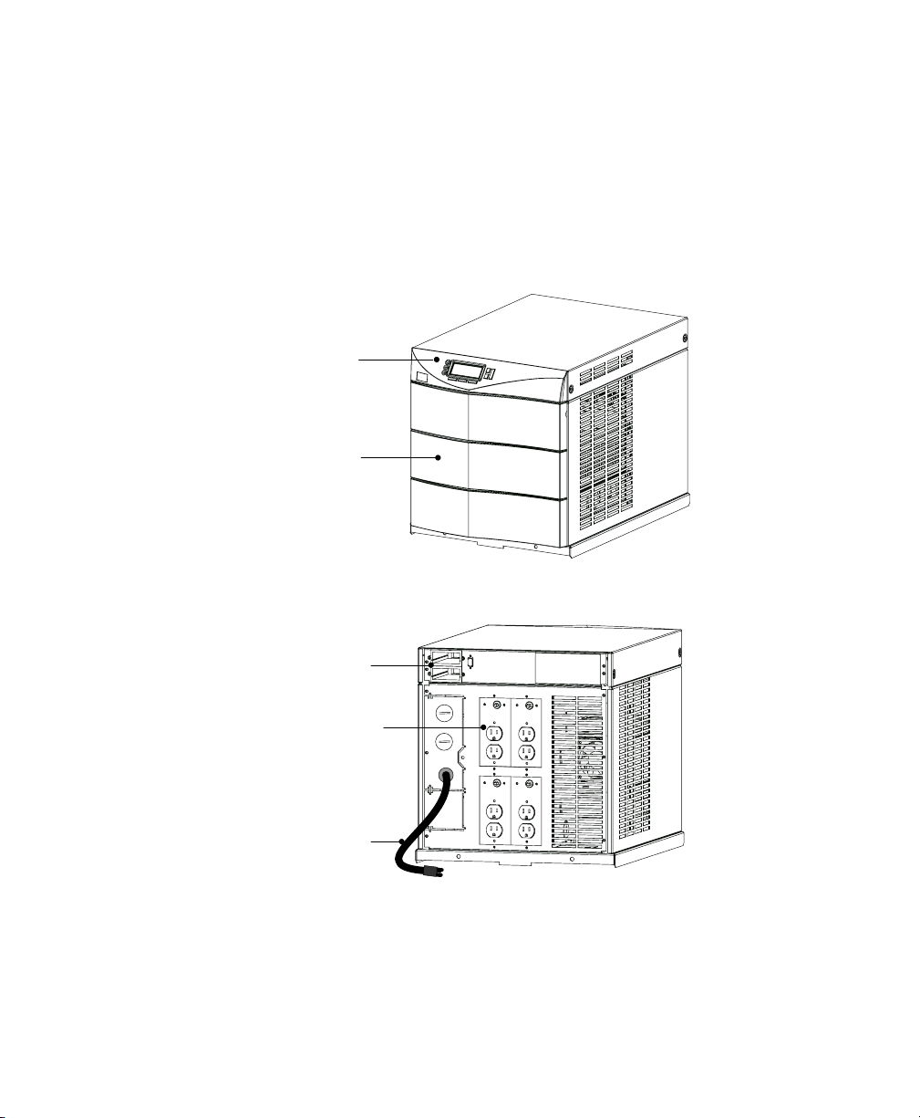
The Powerware 9170 UPS is available in four cabinet sizes. Figure 1
through Figure 6 show the 3-slot and 9-slot configurations and identify
basic Powerware 9170 system features. Six-slot and 12-slot cabinets are
also available; external battery cabinets are available in 6-, 9-, and
12-slot sizes.
Introduction
Front Panel
Display
Front Cover
Bezel
Figure 1. Three-Slot Cabinet (Front View)
BestDock
Ports
Power Outlets
(optional)
Input Power
Cable (optional)
Figure 2. Three-Slot Cabinet (Rear View)
Powerware® 9170 User's Guide LTM-1344 B Uncontrolled Copy
3
Page 8
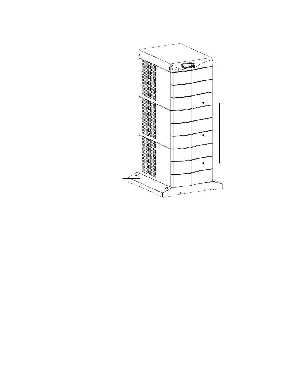
Introduction
Front Panel
Display
Front Cover
Bezels
Cabinet Base
Figure 3. Nine-Slot Cabinet (Front View)
4
Powerware® 9170 User's Guide LTM-1344 B Uncontrolled Copy
Page 9
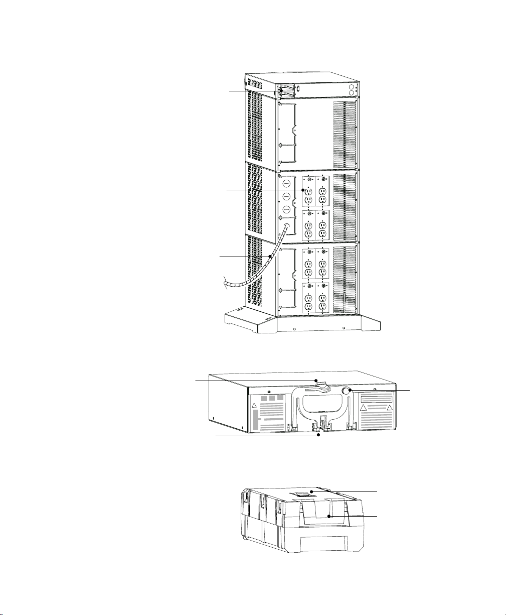
BestDock Ports
Power Outlets
(optional)
Input Power
Cable (optional)
Introduction
Figure 4. Nine-Slot Cabinet (Rear View)
Handle/Latch
Release
Insertion/Extraction
Cams
Figure 5. Power Module (ASY-0528 and ASY-0567)
Figure 6. Battery Module (ASY-0529)
Powerware® 9170 User's Guide LTM-1344 B Uncontrolled Copy
Handle
Thumbscrew
Secondary Stop
Release
Latch Release
5
Page 10

Introduction
6
Powerware® 9170 User's Guide LTM-1344 B Uncontrolled Copy
Page 11

C H A P T E R 2
INSTALLATION SETUP
This chapter explains how to setup and install the Powerware 9170
cabinets:
Unpacking and setup, including clearances and location requirements
Caster cart installation
Stabilizer bracket installation (for 12-slot cabinets with non-isolated
output)
Rack-mount installation
Floor anchor kit installation
Moving the cabinets
Equipment Clearances
All cabinet sizes require the following clearances to allow for servicing
and adequate ventilation:
From the side panels: 6 (15.2 cm)
Top and back: 12 (30.5 cm)
Front: 36 (91.5 cm)
If flexible conduit connects the UPS to the service input and load
distribution panels, you may be able to gain access for servicing by
moving the UPS. If this is the case, you must still leave 12 (30.5 cm)
clearance at the back and 6 (15.2 cm) at the sides of the UPS for
ventilation.
NOTE Do not block the ventilation holes on each side and the back of the unit.
Nine- and 12-slot external battery cabinets may be installed with bases
tight against the UPS cabinet base and against each other. Six-slot
cabinets require 6 of separation.
Powerware® 9170 User's Guide LTM-1344 B Uncontrolled Copy
7
Page 12

Installation Setup
Location Requirements
Install the Powerware 9170 UPS as close as possible to the equipment or
the load distribution panel it will protect. If this distance is more than
25 ft (7.6m), transient noise can reappear in the electrical distribution
system.
If additional Powerware 9170 system batteries are in a separate cabinet,
the external battery cabinet should be located as close as possible to the
Powerware 9170 UPS. If the batteries will be further from the unit than
the standard cables allow, contact your service representative or your
local distributor for assistance.
UPS Unpacking and Setup
The Powerware 9170 UPS is shipped in a carton on a shipping pallet.
Power and battery modules are shipped in separate boxes on another
pallet. Three-slot cabinets and modules are shipped on one pallet.
NOTE Verify that all Powerware 9170 UPS power modules are the proper type for the
UPS cabinet: Universal (single-phase) modules have white labels; split-phase modules
have blue labels. Do not mix blue and white modules in the same UPS cabinet.
To open the UPS carton and remove the UPS from its shipping pallet,
use one of the following procedures. Also refer to the unpacking
instruction sheet (LTS-1724) packed inside the UPS shipping carton.
Three- and Six-Slot Cabinets
1. Open the top of the carton by cutting the banding straps that
hold the carton to the pallet. Open the carton flaps or lift the
cover off.
2. Remove any packing material inside the carton. Also remove
the cartons from the cabinet module slots containing front
panel bezels, electrical or mechanical hardware, and printed
material.
3. Two people are required to lift the cabinet; one to lift the two
front straps and one to lift the two rear straps.
NOTE Do not attempt to lift the cabinet by the module shelves or other convenient
edges or panels.
8
Powerware® 9170 User's Guide LTM-1344 B Uncontrolled Copy
Page 13

Installation Setup
4. If an optional caster cart is included for cabinet mobility, see
Caster Cart Installation" on page 10 for information about
mounting the cabinet on the cart and stabilizing it using the
cart foot pads.
5. After placing the cabinet in its intended operating location, cut
the lifting straps or slip them off the cabinet base tabs.
6. If you are installing an external battery cabinet, continue to
Battery Cabinet Installation" on page 17.
If you do not have an external battery cabinet, continue to UPS
Startup" on page 49 for plug-receptacle units or to Electrical
Installation" on page 23 for hardwired units.
Nine- and Twelve-Slot Cabinets
NOTE The 12-slot Powerware 9170 UPS cabinet with non-isolated output is shipped
with two stabilizer brackets. These brackets must be attached to the wall or the floor
behind the UPS cabinet (see page 11).
1. Open the top of the carton by cutting the straps that hold the
cover to the carton. Lift the cover off.
2. Remove the pallet ramp packed on top of the cabinet. Locate
the ramp-mounting hardware (supplied in the accessory kit)
and attach the ramp to the pallet as shown in LTS-1724,
accompanying the hardware.
3. Remove any packing material inside the carton. Also remove
cartons containing front panel bezels, electrical or mechanical
hardware, and printed material.
4. Lower the four cabinet casters (one at each corner of the
cabinet base) by using a 1/2 hex-style socket wrench to turn
each bolt clockwise.
5. With all casters fully extended, carefully roll the cabinet down
the ramp and to its intended operating location.
6. To stabilize the cabinet in its operating location, turn the four
caster bolts counter-clockwise until the cabinet rests on the
floor. Place a plastic cap into each bolt access hole.
Powerware® 9170 User's Guide LTM-1344 B Uncontrolled Copy
9
Page 14
Installation Setup
NOTE If the floor is uneven and the cabinet is tilted or unstable, you may need to
place a thin steel plate under a corner. Do not use the caster bolts to level the
cabinet.
7. If you are installing an external battery cabinet, continue to
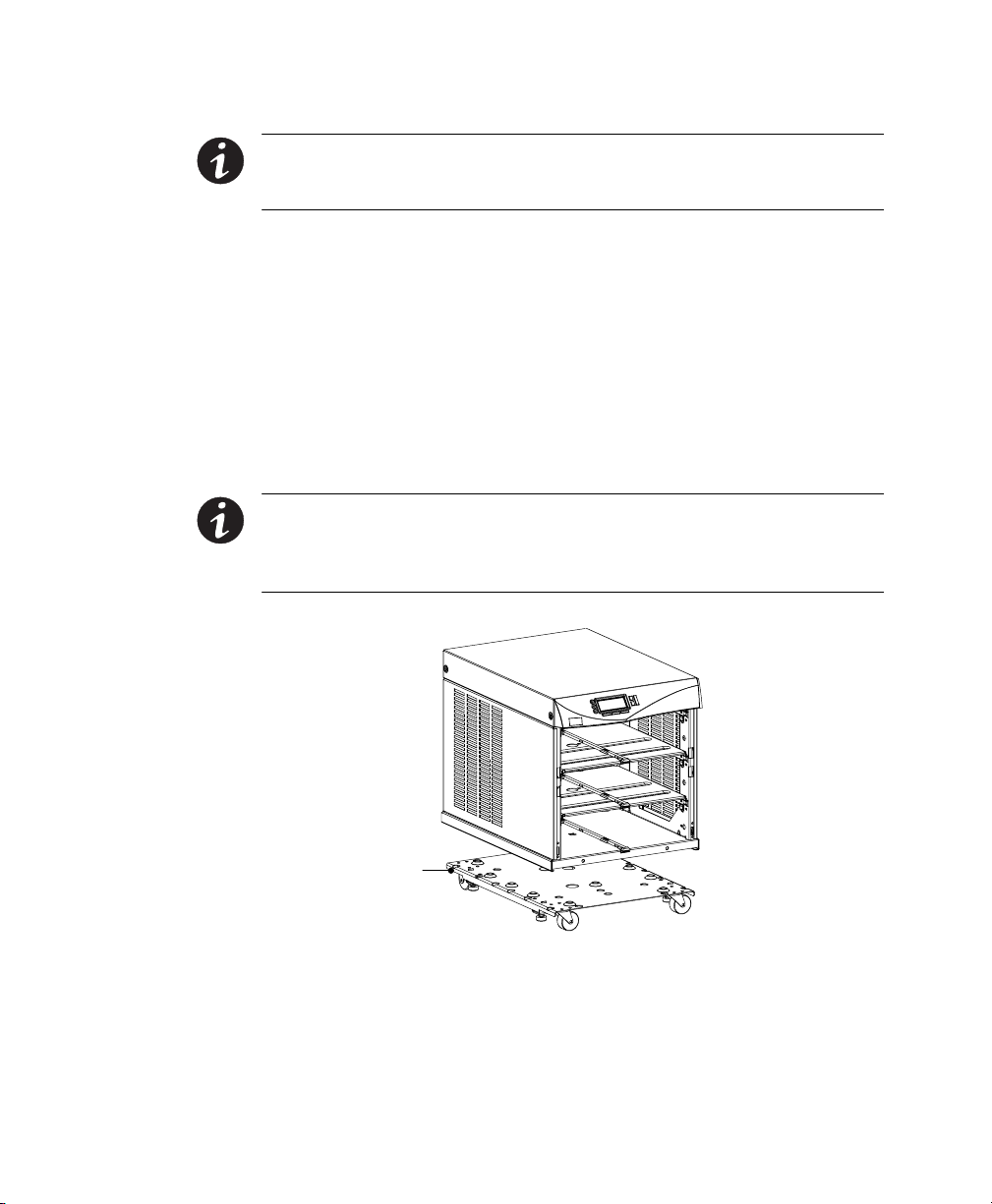
Caster Cart Installation
An optional caster cart (ASY-0527) is available for 3- and 6-slot cabinets
for increased mobility of the UPS (see Figure 7).
NOTE The UPS cabinet is heavy. This procedure requires two people to lift and
position the cabinet onto the caster cart. Lift the cabinet using four lifting straps
shipped with the cabinet; do not attempt to lift the cabinet by the module shelves or
other convenient edges or panels.
Battery Cabinet Installation" on page 17.
If you do not have an external battery cabinet, continue to UPS
Startup" on page 49 for plug-receptacle units or to Electrical
Installation" on page 23 for hardwired units.
10
Caster Cart
Figure 7. Three-Slot Cabinet Being Lowered onto Caster Cart
The caster cart, shipped separately from the UPS cabinet, must be placed
under the cabinet before installing power and battery modules, and
before plugging the UPS into the intended power outlet.
Powerware® 9170 User's Guide LTM-1344 B Uncontrolled Copy
Page 15

The cart requires no bolts or other hardware to fasten it to the UPS
cabinet. It is shaped to fit securely under the cabinet, ensuring proper
alignment after placing the cabinet on the cart.
Four foot pads under the cart keep the cart from rolling when it is in its
intended location. Turn each threaded foot to lower it to the floor.
When the foot is tight against the floor, turn the lock nut on the
threaded foot up tight against the bottom of the cart to keep the foot
from rotating.
If leveling of the UPS is required, use the foot pads to raise a side or
corner before locking them with their lock nuts.
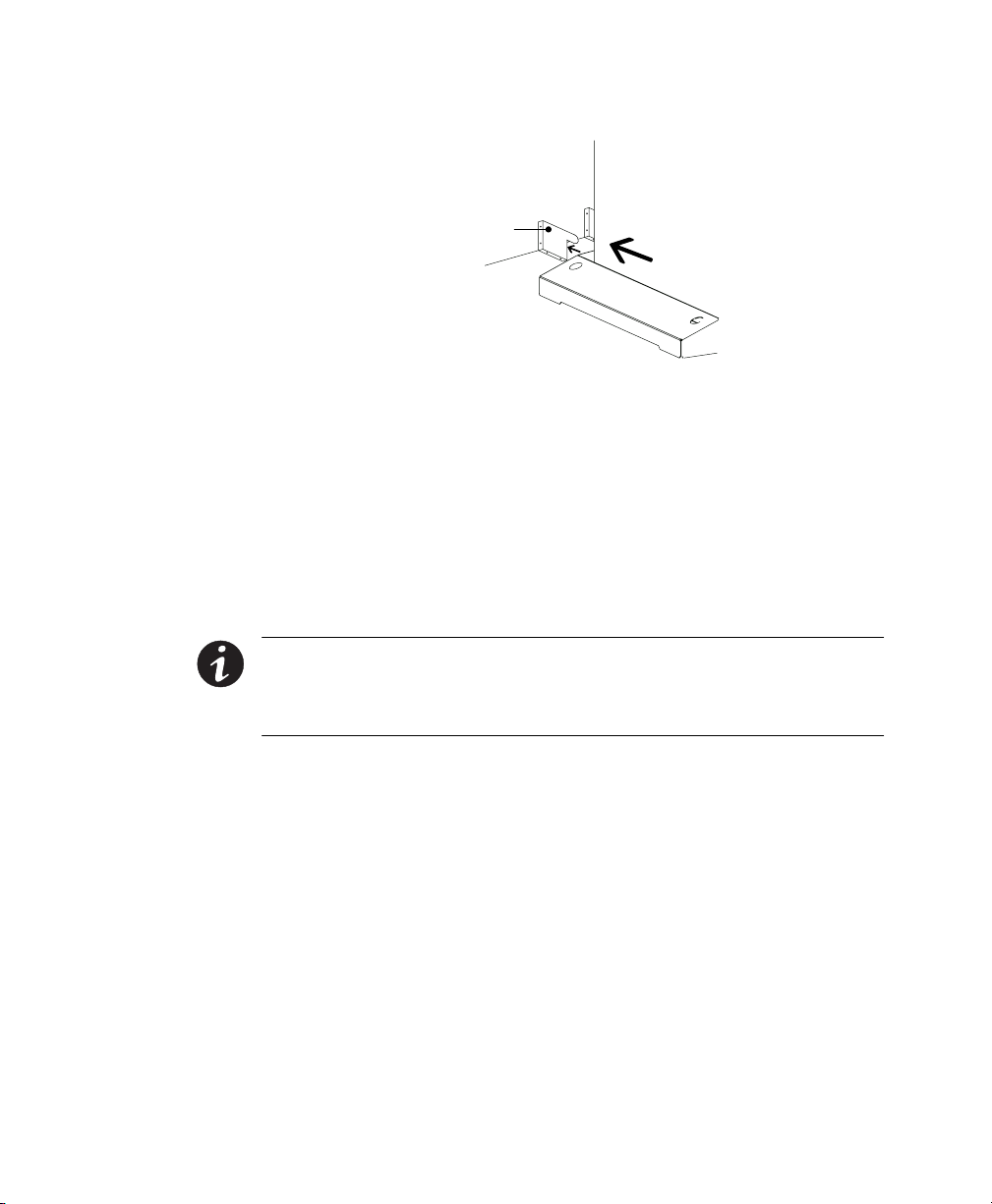
Stabilizer Bracket Installation
The 12-slot Powerware 9170 UPS cabinet with non-isolated output is
shipped with two stabilizer brackets. These brackets must be attached to
the wall or the floor behind the UPS cabinet. Under all module-loading
conditions, they act as a protective stop to prevent the cabinet from
falling forward if it is unintentionally pushed away from the wall.
As shown in Figure 8, each bracket has holes that enable it to be
attached by screws to either the wall or the floor (or both) behind the
intended cabinet installation. The brackets are not attached to the
cabinet base itself. Install the brackets as follows.
1. Select the location for the brackets, approximately 1216
(3041 cm) apart, at the floor/wall intersection behind the
intended cabinet location.
2. Using the proper type of customer-supplied screws for the
intended mounting surface, attach each bracket as shown in
Figure 8. All screws must be driven into structural material
such as wall studs.
3. Roll the UPS cabinet to its intended location, positioning the
rear section of the cabinet base under the open ends of the
stabilizer brackets, as far as the cabinet will go.
4. Turn all four caster bolts counter-clockwise until the cabinet
rests on the floor. Place a plastic cap into each bolt access hole.
Installation Setup
NOTE If the floor is uneven and the cabinet is tilted or unstable, you may need to
place a thin steel plate under a corner. Do not use the caster bolts to level the
cabinet.
Powerware® 9170 User's Guide LTM-1344 B Uncontrolled Copy
11
Page 16
Installation Setup
Rack-Mount Installation
The 3- and 6-slot UPS cabinets may be installed in an EIA-standard 19
(48.3-cm) equipment rack. An optional rack-mounting kit (ASY-0547),
containing brackets and required hardware, is available for such an
installation. For each 3-slot section, use the following mounting
procedure to convert the UPS cabinet and install it in the equipment
rack:
Stabilizer Bracket
Figure 8. Stabilizer Bracket Installation
12
NOTE The UPS cabinet is heavy. This procedure requires two people to lift and
position the cabinet into the equipment rack. Install the cabinet in the rack before
installing power and battery modules, and before plugging the UPS into the intended
power outlet.
1. Remove the four screws (two on either side) securing the top
cover of the UPS cabinet. Carefully lift the cover straight up and
off, to avoid stressing the front panel display. Set the cover
aside.
2. Remove the two cabinet side panels (4 panels in 6-slot cabinets)
by lifting the top edge. No other hardware must be detached.
Store or discard the side panels.
3. Carefully replace the UPS cabinet top cover and secure with the
four screws removed in Step 1. Position the cover lip to fit
behind the front display panel.
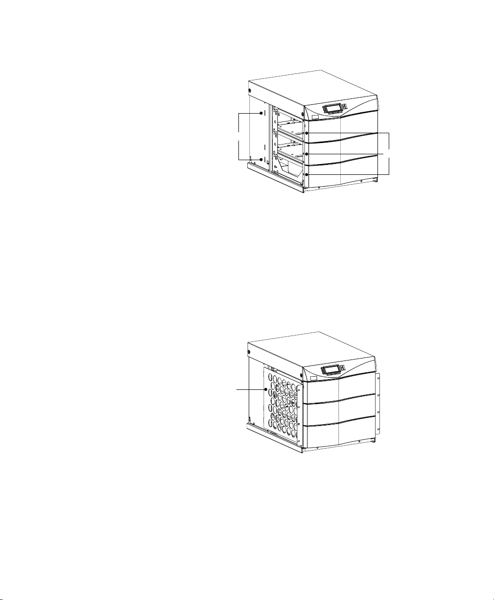
4. Install three metal clip-nuts onto each side flange (6 clip-nuts
on 6-slot cabinets) along the front of the UPS cabinet (see
Figure 9).
Powerware® 9170 User's Guide LTM-1344 B Uncontrolled Copy
Page 17
Installation Setup
Tab Slots
Metal Clip-Nuts
Figure 9. Metal Clip-Nut and Tab Slot Locations
5. Install a rack-mount ear (2 for 6-slot cabinets) on each side of
the UPS cabinet (see Figure 10).
Insert the two offset tabs on the rear edge of the ear into the
matching tab slots on the cabinet side frame (see Figure 9).
Pivot the ear forward, until it is flush against the UPS cabinet
side frame. Secure each ear with three 1/4-201/2
Phillips-head bolts, screwed into the metal clip-nuts installed in
Step 4.
Rack-Mount Ear
6. Select the position for the UPS in the equipment rack.
7. Install one equipment rail on each side of the rack using four
10-321/2 flat-head screws per rail. Select the proper holes in
the rail that position the UPS at the desired location in the rack
(see Figure 11).
Powerware® 9170 User's Guide LTM-1344 B Uncontrolled Copy
Figure 10. Rack-Mount Ear Installed
13
Page 18
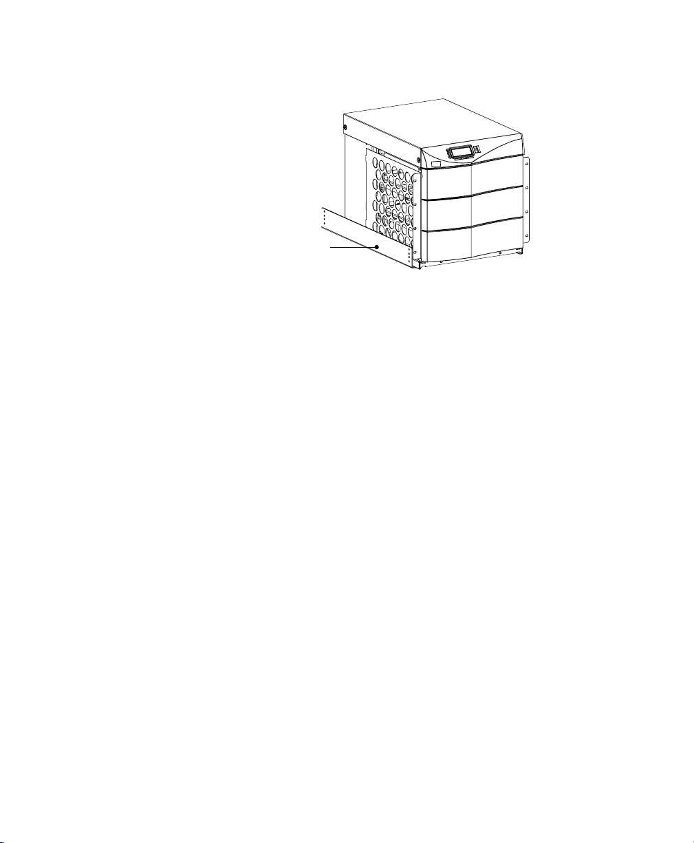
Installation Setup
Equipment Rail
Figure 11. Rails Holding UPS
8. With one person lifting each side of the UPS cabinet, position
the cabinet onto the two equipment rails.
Carefully slide the UPS into the equipment rack until the
rack-mount ears of the cabinet are flush with the front vertical
rails of the rack. Verify that the holes in the ears align with the
holes in the rack.
9. Secure the UPS in the rack using eight 10-321/2 torx screws
(16 for 6-slot cabinets) or other appropriate customer-specified
screws.
Floor Anchor Kit Installation
An optional floor anchor kit (ASY-0548) is available for all sizes of the
Powerware 9170 UPS. The kit helps to stabilize the UPS or battery
cabinet in the event of accidental bumps or small floor movements. Any
testing to specific seismic requirements is the responsibility of the
customer.
The floor anchor brackets, shipped separately from the UPS and battery
cabinet, should be attached inside the lower front and rear edges of the
cabinet before installing power and battery modules, and before making
connections to the intended power source.
Use mounting hardware supplied with the floor anchor kit to attach the
brackets to the UPS or external battery cabinet (see Figure 12). The
customer is responsible for specifying and supplying floor mounting
bolts.
14
Powerware® 9170 User's Guide LTM-1344 B Uncontrolled Copy
Page 19
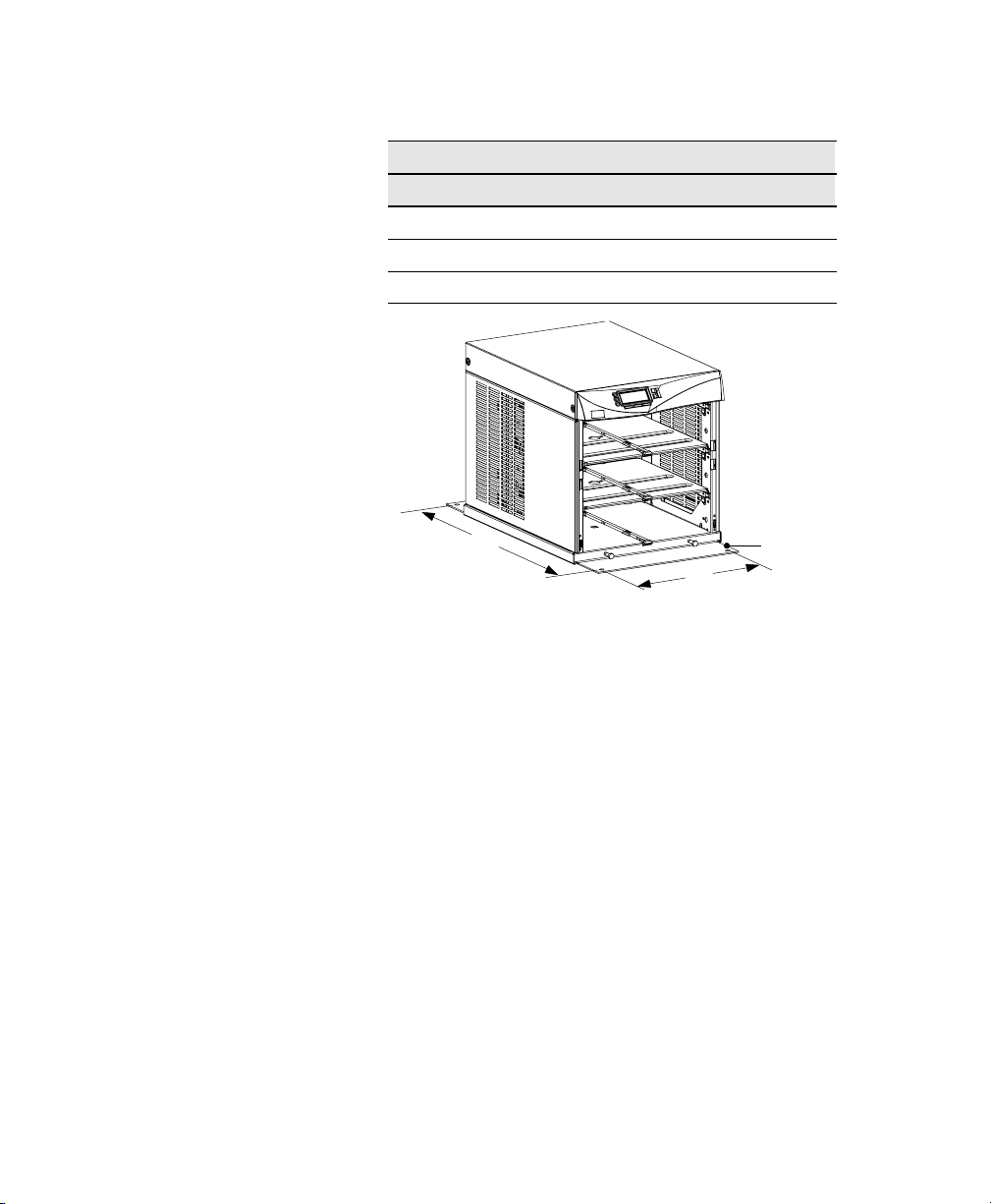
Mounting Centers for 5/16 (8-mm) Floor Bolts
Dimension (see Figure 12) Measurement
A 14.5 (36.8 cm)
B (3- and 6-slot cabinets) 30.25 (76.8 cm)
B (9- and 12-slot cabinets) 34.25 (87 cm)
Installation Setup
Moving the Cabinets
The Powerware 9170 UPS and the battery cabinet are very heavy with
power and battery modules installed. Before moving the cabinets,
remove the power and battery modules and move these modules
separately from the cabinets.
The smaller (3- and 6-slot) cabinets may be ordered with a caster cart, to
enable moving the cabinet. Caster Cart Installation" on page 10
describes how to set the four foot pads on this cart to keep the cabinet
from rolling when properly positioned.
The larger (9- and 12-slot) cabinets have casters built into the cabinet
base. Use the following procedure to raise the cabinet before rolling it
on its casters. For 12-slot cabinets that do not have output isolation, see
Stabilizer Bracket Installation" on page 11, for details about mounting
stabilizer brackets before rolling the cabinet into place.
1. Ensure that the cabinet contains no power or battery modules.
2. Locate the four plastic caps covering the caster bolts. They are
B
A
Figure 12. Floor Anchor Brackets Bolted to UPS Cabinet
at the corners of the cabinet base.
Floor Anchor
Bracket
Powerware® 9170 User's Guide LTM-1344 B Uncontrolled Copy
15
Page 20

Installation Setup
3. Pry the caps out of the bolt access holes.
4. Use a 1/2 hex-style socket wrench to turn each of the four
bolts clockwise. Doing so lowers the casters to allow the cabinet
to roll on the casters.
5. After rolling the cabinet to its intended position, turn all four
caster bolts counter-clockwise until the cabinet rests on the
floor. Place a plastic cap into each bolt access hole.
NOTE If the floor is uneven and the cabinet is tilted or unstable, you may need to
place a thin steel plate under a corner. Do not use the caster bolts to level the
cabinet.
After properly positioning and leveling the cabinet, insert power and
battery modules into the rack as described in UPS Startup" on page 49.
16
Powerware® 9170 User's Guide LTM-1344 B Uncontrolled Copy
Page 21

C H A P T E R 3
BATTERY CABINET INSTALLATION
If you are not installing battery modules into a separate external battery
cabinet, continue to UPS Startup" on page 49 for plug-receptacle units
or to Electrical Installation" on page 23 for hardwired units.
W A R N I N G
Only qualified service personnel (such as a licensed electrician) should perform the
battery cabinet installation. Risk of electrical shock.
C A U T I O N
Before connecting an external battery cabinet to the UPS cabinet or to another
external battery cabinet, verify that all AC input power is removed from the UPS.
Open the input service circuit breaker or turn the external bypass switch to the
SERVICE position.
Disconnect all battery strings in the UPS cabinet and/or battery cabinet to ensure
DC voltage is removed from the internal DC buses. You can remove all battery
modules or unplug each pair of battery modules from the cabinet backplane.
1. Open the carton containing the external battery cabinet cable
assembly, and check that all required parts have been shipped
with it.
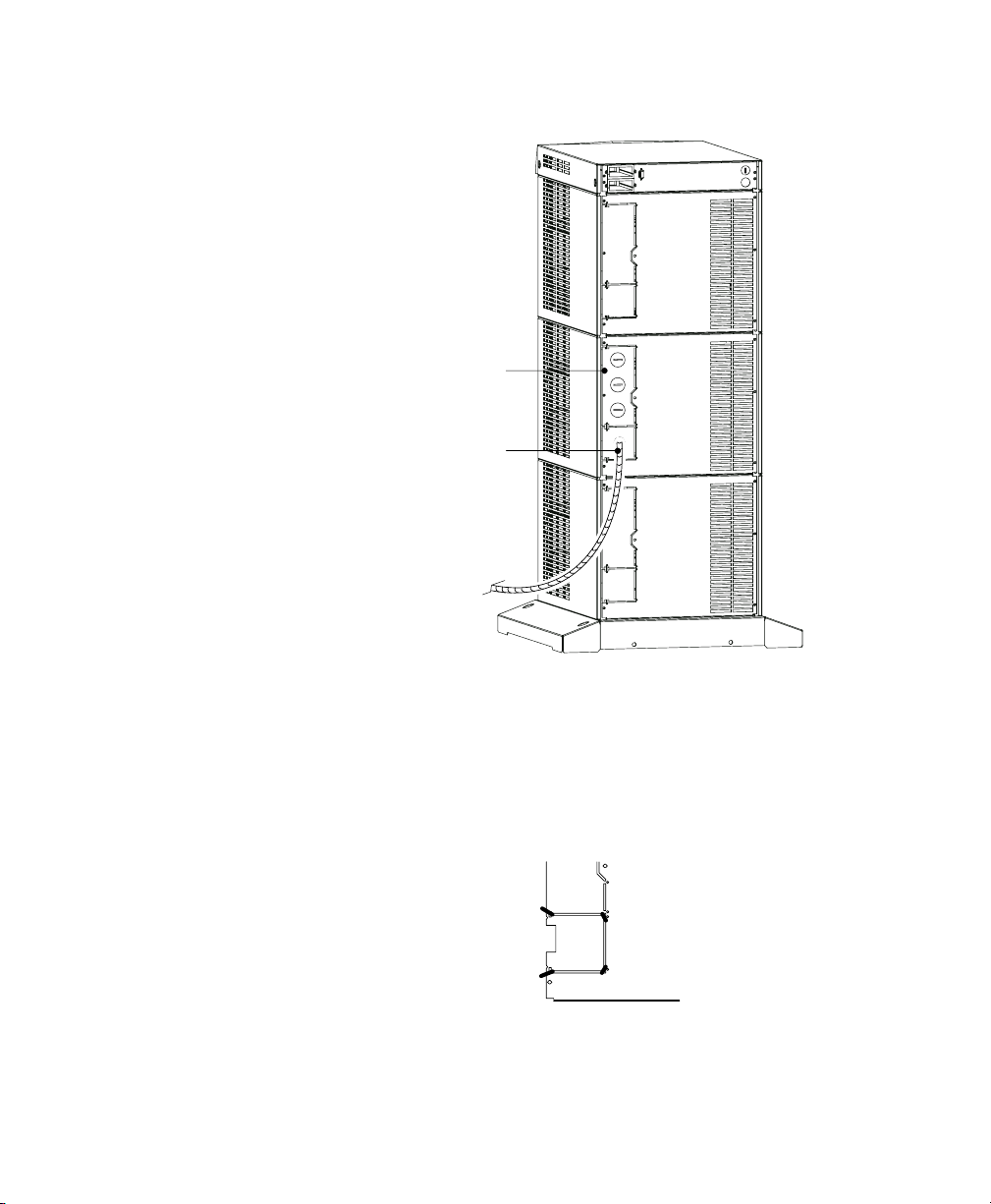
2. Locate the 3-slot section in the UPS cabinet that contains the
power entrance panel. Unscrew and remove the rear panel of
this section (see Figure 13).
Powerware® 9170 User's Guide LTM-1344 B Uncontrolled Copy
17
Page 22
Battery Cabinet Installation
Entrance Panel
Battery Cable
18
Figure 13. UPS Power Entrance Panel
3. Use a pair of pliers to bend the narrow links (1 and 2 in
Figure 14) between the outer edge of the lower breakaway
panel and the rear panel.
4. Use the pliers to bend the entire breakaway panel (at 3 and 4 in
Figure 14) until it breaks away.
1
2
4
3
Figure 14. Breakaway Panel Links
5. Verify all hazardous voltages have been removed from the
backplane by testing with a voltmeter or other test device.
Powerware® 9170 User's Guide LTM-1344 B Uncontrolled Copy
Page 23
Battery Cabinet Installation
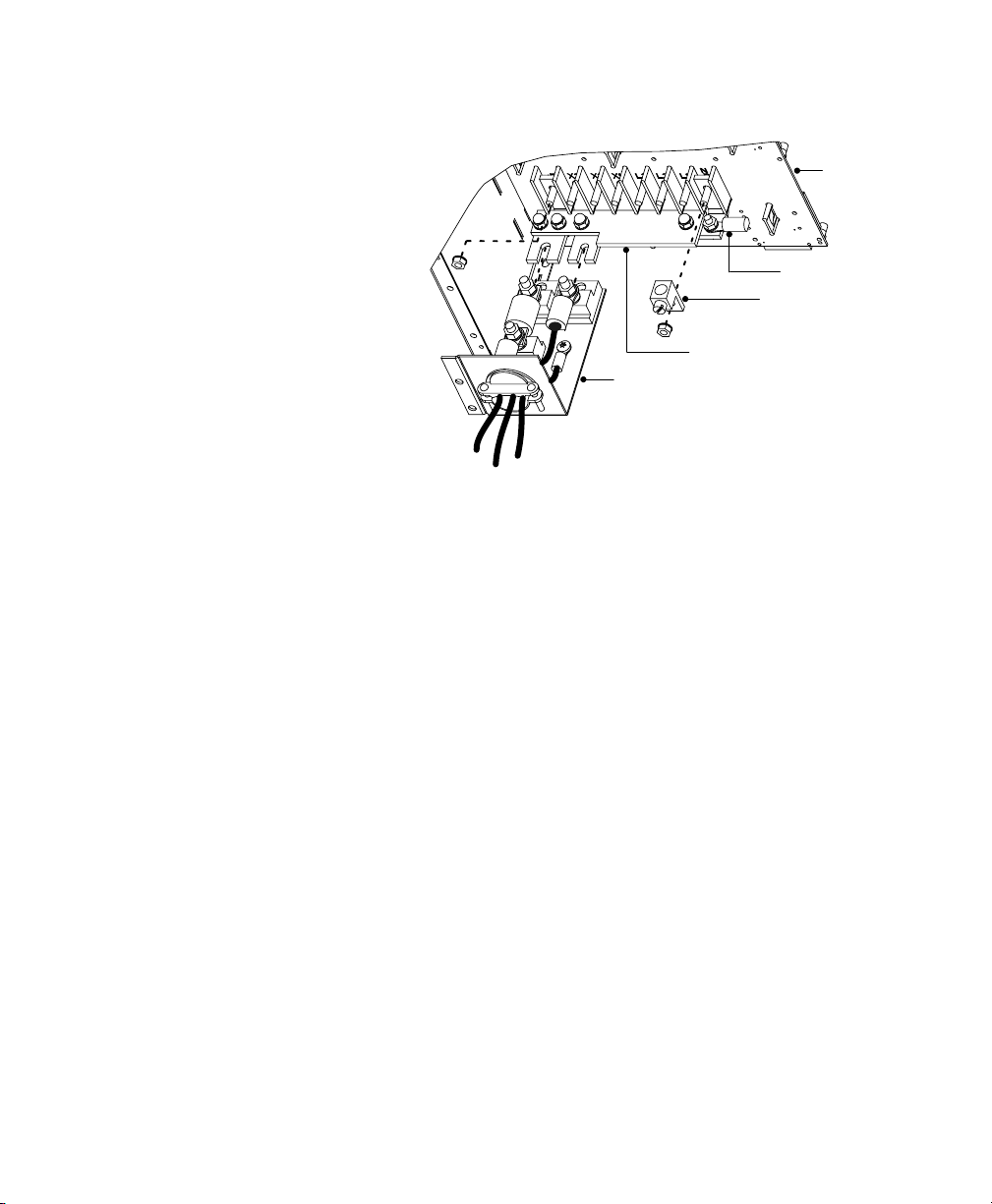
Backplane
Ring Terminal
Compression Lug
Bus-Bar Extension Assembly
Cable Assembly
Figure 15. Bus-Bar Extension Installation
6. Remove the nuts holding the +DC and the DC bus bars to the
backplane as shown in Figure 15. Remove the ring terminal and
the compression lug from the DC bolt.
7. Position the bus-bar extension assembly onto the +DC and DC
bolts as shown in Figure 15. Replace the compression lug onto
the DC bolt of the bus-bar extension assembly. Secure the
assembly by replacing the two nuts removed in Step 6.
8. Use the bolt and nut supplied with the cable assembly to attach
the ring terminal to the empty hole in the DC bus bar.
9. Torque all three bolts to 7585 in lb (8.59.6 Nm).
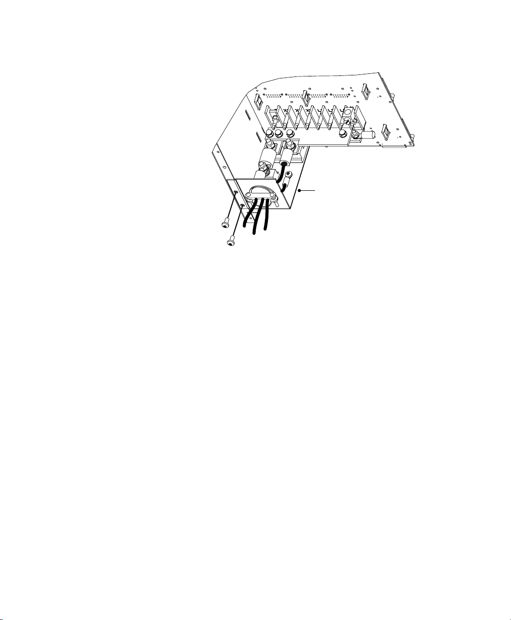
10. Loosen the three large nuts on the end of the cable assembly
(see Figure 15).
11. Slip the terminals of the cable assembly onto the tabs of the
bus-bar extension, putting the tabs between the stud block and
the fuse end and between the other stud block and the cable
terminal.
Powerware® 9170 User's Guide LTM-1344 B Uncontrolled Copy
19
Page 24
Battery Cabinet Installation
Cable Assembly
Figure 16. Battery Cable Assembly Installation
12. Align the screw holes of the cable assembly's entry plate with
holes on the cabinet side panel as shown in Figure 16. Secure
the entry plate with screws supplied with the cable assembly.
13. If the battery cable will be installed in customer-supplied
flexible or other conduit (as required by local wiring codes),
loosen the two screws holding the strain-relief clamp shown in
Figure 16. Remove the clamp by loosening the star nut on the
inside of the entry plate, leaving the nut in place. Replace the
clamp with a panel-to-conduit feedthrough and secure it with
the star nut.
14. Secure the cable assembly terminals by tightening the nuts onto
the backplane bus bars. Also tighten the third nut, holding the
other fuse end. Torque all three nuts to 7585 in lb
(8.59.6 Nm).
15. Replace the UPS cabinet rear panel with the screws removed in
Step 2 on page 17.
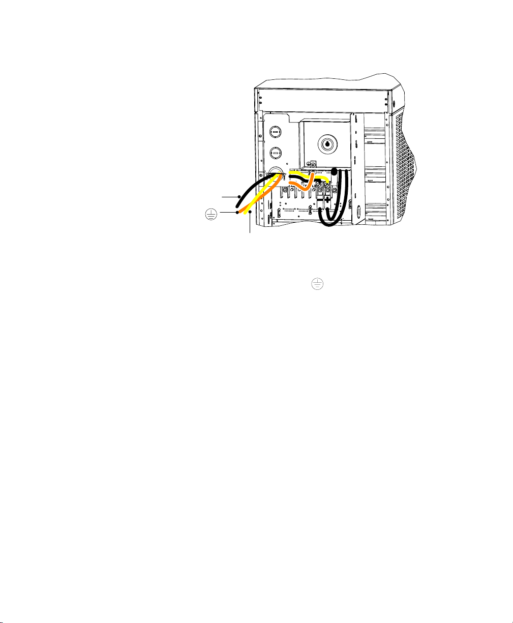
16. If the battery cable will be installed in flexible or other conduit,
pull the conductors through the conduit. Attach the conduit to
both the UPS power entrance panel and the battery cabinet
entrance panel as shown in Figure 17.
20
Powerware® 9170 User's Guide LTM-1344 B Uncontrolled Copy
Page 25
Battery Cabinet Installation
+
Figure 17. Battery Cable Installed in Battery Cabinet
17. Secure the +, the , and the conductors to the proper
compression lugs on the battery cabinet backplane as shown in
Figure 17. Torque all three compression lugs to 7585 in lb
(8.59.6 Nm).
18. If an additional battery cabinet will be connected to the first, in
a daisy-chain configuration, use another external battery
cabinet cable assembly for the connections between the battery
cabinets.
19. Locate the daisy-chained cable on the rear of the first battery
cabinet in the section below the location of the first cable
assembly. Follow this procedure for connecting any additional
daisy-chained battery cabinets.
20. Install the remaining cabinet rear panels using the original
screws.
21. If your UPS is a hardwired unit, continue to Electrical
Installation" on page 23. If you have a plug-receptacle unit,
skip to UPS Startup" on page 49.
Powerware® 9170 User's Guide LTM-1344 B Uncontrolled Copy
21
Page 26

Battery Cabinet Installation
22
Powerware® 9170 User's Guide LTM-1344 B Uncontrolled Copy
Page 27
C H A P T E R 4
ELECTRICAL INSTALLATION
NOTE If you have a plug-receptacle unit, continue to UPS Startup" on page 49.
Only qualified service personnel (such as a licensed electrician) should perform the
electrical installation. Risk of electrical shock.
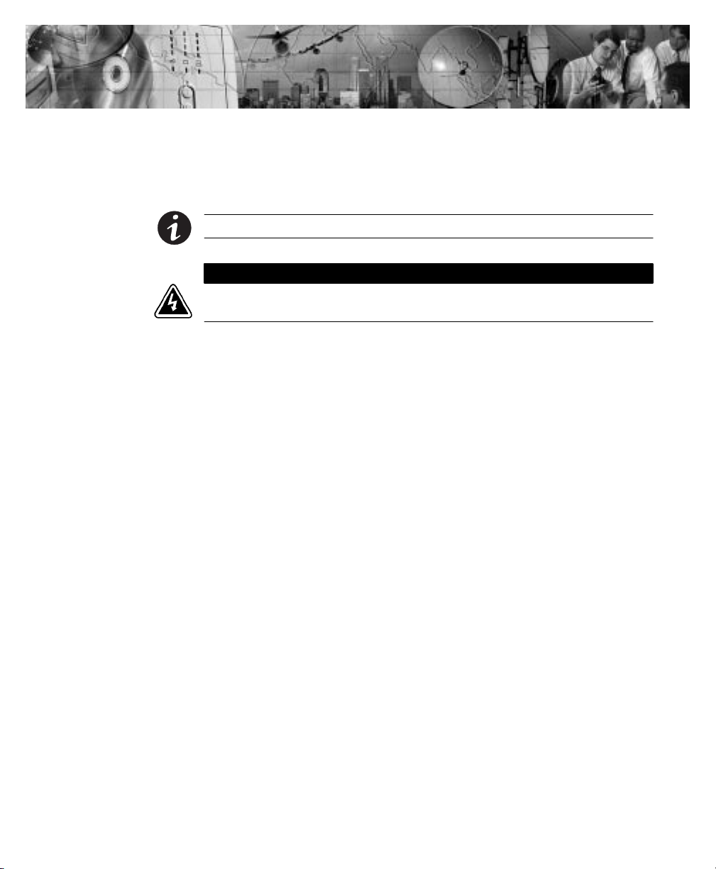
The Powerware 9170 UPS input power may be hardwired through
conduit to either a main power source circuit breaker or to an optional
external bypass switch. For hardwired installations, it is recommended
that you install a Powerware bypass switch to enable power transfer
during maintenance or UPS downtime. If a bypass switch is used, both
UPS input and UPS output must be hardwired
conduitsto the bypass switch, as shown in Figure 18.
W A R N I N G
through separate
Powerware® 9170 User's Guide LTM-1344 B Uncontrolled Copy
23
Page 28
Electrical Installation
External Bypass Switch
Off
Service
Line
Building
Service
Panel
Off
Service
Line
Off
Service
Line
UPS
UPS
UPS
User-supplied
(If Required)
Load
Distribution
Panel
External Batteries
(Optional)
24
Figure 18. Typical Installation with a Bypass Switch
Powerware® 9170 User's Guide LTM-1344 B Uncontrolled Copy
Page 29
Electrical Installation
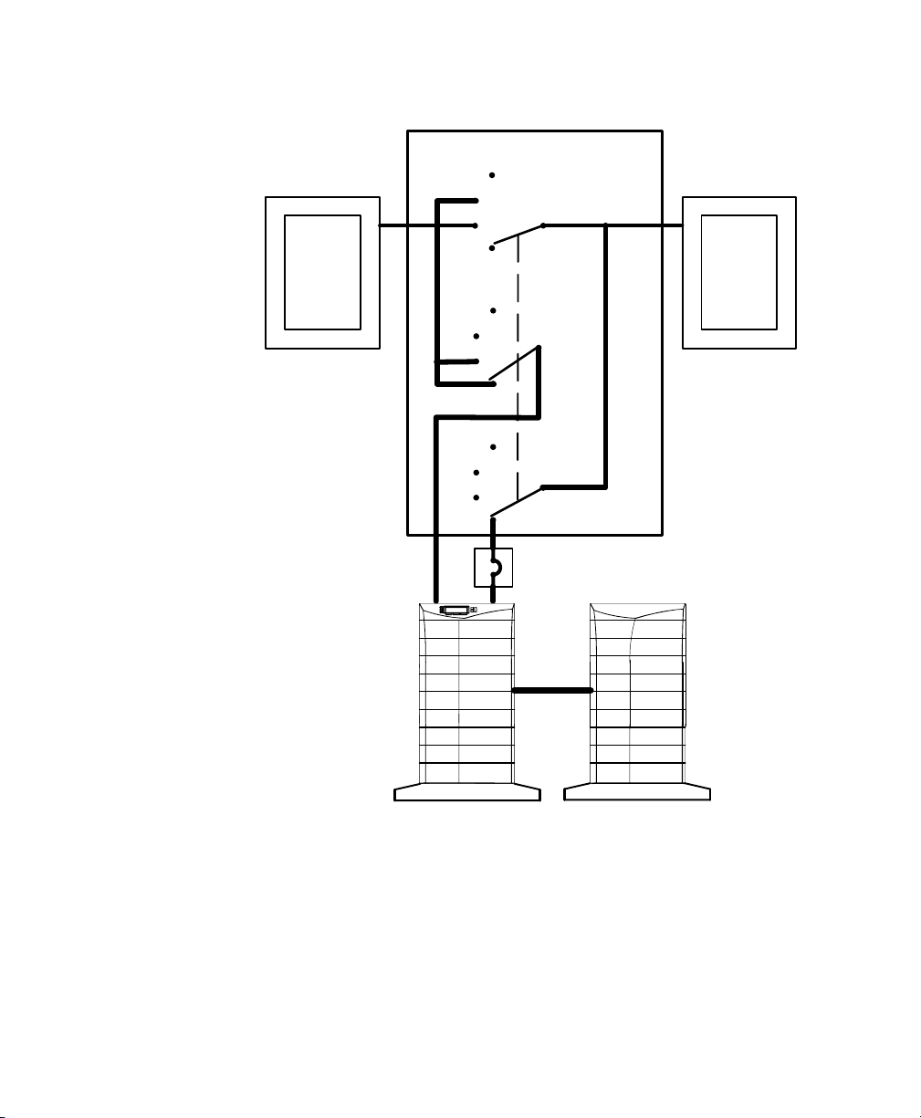
If a bypass switch is not used, the UPS input may be hardwired through
conduit to a main power source circuit breaker, and the UPS output may
either be hardwired to a circuit breaker in a distribution panel (as shown
in Figure 19) or supplied to loads through receptacles on the back of the
UPS. Without a bypass switch, power to the load cannot be maintained
if the UPS is taken completely offline.
Building
Service
Panel
User-supplied
(If Required)
Load
Distribution
Panel
External Batteries
(Optional)
Figure 19. Typical Installation without a Bypass Switch
Powerware® 9170 User's Guide LTM-1344 B Uncontrolled Copy
25
Page 30

Electrical Installation
Input Current Ratings
Table 1 contains the required circuit breaker ratings for hardwired
installations. Circuit breaker ratings for units having an input line cord
are determined by the current capacity of the line cord.
Table 1. Required Input Circuit Breaker Sizes (200240 Vac, 50/60 Hz)
NOTE To accommodate the feature of easy system expandability, it is recommended
that initial installation of the Powerware 9170 UPS contain wiring to support the
maximum capacity of the UPS cabinet: 3 kVA for 3-slot cabinets; 9 kVA for 6-slot
cabinets; 18 kVA for 9- and 12-slot cabinets.
UPS Capacity Circuit Breaker Rating
3 kVA 25A
6 kVA 40A
9 kVA 60A
12 kVA 80A
15 kVA 100A
18 kVA 125A
26
See Table 2 for recommended conductor sizes to wire the input circuit
breakers.
Powerware® 9170 User's Guide LTM-1344 B Uncontrolled Copy
Page 31

Electrical Installation
Table 2. Recommended Wire Sizes
Input Circuit Breaker Size 75°C Copper Wire Size Conductor Screw Torque
25A 10 AWG (5.3 mm2) 20 in lb (2.3 Nm)
40A 8 AWG (8.4 mm2) 25 in lb (2.8 Nm)
60A 4 AWG (21.2 mm2) 35 in lb (4.0 Nm)
80A 3 AWG (26.7 mm2) 45 in lb (5.1 Nm)
100A 2 AWG (42.1 mm2) 55 in lb (6.2 Nm)
125A 1/0 AWG (53.5 mm2) 65 in lb (7.3 Nm)
FOR U.S. INSTALLATIONS, READ THIS IMPORTANT NOTE!
This table lists the AWG and mm2 wire size for each circuit breaker size shown on the wiring diagrams. The minimum
recommended circuit breaker sizes for each model and voltage application are listed on the wiring diagrams.
Conductor sizes shall be no smaller than the 75°C wire size based on the ampacities given in Table 31016 of the National
Electrical Code, ANSI/NFPA 70-1999, and article 220. All circuit conductors, including the neutral and equipment grounding
conductors, must be the same size (ampacity) wire. Code may require a larger AWG size than shown in this table because
of temperature, number of conductors in the conduit, or long service runs. Follow local code requirements.
Bypass Switches
Bypass switches are available in two types: Make-Before-Break (MBB)
and Break-Before-Make (BBM).
An MBB switch makes a new connection before it breaks the original
connection. For example, if you turn an MBB switch from UPS to LINE,
the bypass switch connects the load to AC input power before
disconnecting the load from UPS output power. (As noted in Figure 37
on page 47, MBB switches may not be used in certain system
configurations.)
A BBM switch breaks the original connection before it makes a new one.
If you turn a BBM switch from UPS to LINE, the switch disconnects the
load from UPS output power before connecting the load to AC input
power.
The bypass switch has four positions as described in Table 3.
NOTE In the UPS or LINE position, AC input power is still connected to the input
terminals inside the UPS.
Powerware® 9170 User's Guide LTM-1344 B Uncontrolled Copy
27
Page 32

Electrical Installation
Continuous
Table 3. Bypass Switch Positions
Switch Position Description
LINE Connects the load directly to AC input power and disconnects UPS output. AC input power is still
connected to the UPS input.
OFF Disconnects the load from the UPS output power and AC input power, as well as AC input power
to the UPS input.
UPS Connects the UPS output to the load.
SERVICE Like the LINE position, SERVICE connects the load directly to AC input power and disconnects
UPS output. However, because SERVICE also disconnects AC input from the UPS, this is
the appropriate position for UPS maintenance or repair.
To disconnect AC input power during maintenance or service, turn the
bypass switch to the SERVICE position. For MBB switches, you must
press the red button beside the switch before you can change the switch
position.
There are six bypass switch models available for the Powerware 9170
UPS as specified in Table 4.
Table 4. Bypass Switch Specifications
BPE12BBM1A BPE12MBB1A 40A/300 Vac
BPE14BBM1A BPE14MBB1A 80A/300 Vac 21.0
BPE22BBM1A BPE22MBB1A 150A/300 Vac 26.5
28
Bypass Switch Models
BBM MBB
Rating,
Continuous
(CSA)
50A/300 Vac
(UL,TÜV)
See Figure 20
Height Width Depth Mounting Centers
(A) (B) (C) (D) (E)
21.0
(534 mm)
(534 mm)
(673 mm)
14.0
(356 mm)
14.0
(356 mm)
18.4
(467 mm)
Powerware® 9170 User's Guide LTM-1344 B Uncontrolled Copy
6.8
(172 mm)
6.8
(172 mm)
6.6
(168 mm)
11.0
(280 mm)
11.0
(280 mm)
16.0
(406 mm)
20.0
(508 mm)
20.0
(508 mm)
25.5
(648 mm)
Weight
27 lb
(12.3 kg)
31 lb
(14.1 kg)
53 lb
(24.1 kg)
Page 33

Electrical Installation
D
A
E
Figure 20. Bypass Switch Mounting Dimensions
Powerware® 9170 User's Guide LTM-1344 B Uncontrolled Copy
B
C
29
Page 34

Electrical Installation
UPS Installation with an External Bypass Switch
A R N I N G
W
Only qualified service personnel (such as a licensed electrician) should perform the
electrical installation. Risk of electrical shock.
C A U T I O N
To prevent electrical shock or damage to the equipment, verify that the Powerware
9170 UPS is OFF before you remove the entrance panel. The circuit breaker or
disconnect switch must also be off at the AC input service panel. Also, turn OFF the AC
disconnect and bypass switches before you connect any wires to the bypass switch
terminal strip.
1. Mount the bypass switch within sight of the UPS. If you do not
have a Powerware bypass switch or the fuse box or panel is out
of sight, you must install a separate disconnect switch next to
the UPS.
The bypass switch should be mounted securely to a sturdy
surface. You may need to turn the cabinet 90 degrees (on its
side) to enable operator access to the switch handle.
2. Remove the six screws in the bypass switch front panel and
remove the panel. Remove any packing material inside the
bypass switch.
Remove knockouts in the bottom of the bypass switch for AC
Line Input, AC to UPS Input, AC from UPS Output, and AC to
the UPS load.
30
Powerware® 9170 User's Guide LTM-1344 B Uncontrolled Copy
Page 35

Entrance Panel
Battery Cable
Electrical Installation
Wiring Access Hole
for Optional EPO and
Bypass Input Signals
Wiring Access Hole
for an Optional
Generator Input
Signal
Figure 21. UPS Power Entrance Panel
3. Remove the rear panels of the UPS (top panel on 3- or 6-slot;
top 2 panels on 9- and 12-slot) as shown in Figure 21.
The entrance panel contains knockout openings for entrance
and exit conduits and for conduit to an optional external
battery cabinet. The entrance panel is located on the top 3-slot
section for 3- and 6-slot cabinets; on the second section for 9and 12-slot cabinets as shown in Figure 21.
Wiring for optional EPO and bypass input signals passes
through the opening at the top back of the cabinet. Wiring for
an optional generator input signal must pass through a separate
opening. Installing this wiring is described in Steps 11 and 12.
4. Remove the knockouts in the entrance panel for AC input and
AC output wiring.
Powerware® 9170 User's Guide LTM-1344 B Uncontrolled Copy
31
Page 36

Electrical Installation
5. Install the conduit adapters. AC input and AC output
conductors must be run through separate conduits. UPS output
circuits must be installed in dedicated conduit systems and not
shared with other electrical circuits.
6. Find the terminal strip inside the bypass switch cabinet. Using
the label on the back of the bypass switch access panel and the
proper installation wiring diagram, make the terminal strip
connections and tighten all connections as specified in Table 2
on page 27. Use copper wire that is the appropriate size for the
current draw. Figure 22 shows a sample label.
32
Figure 22. Bypass Switch Wiring Label
7. After installing bypass switch wiring, torque the screws holding
all input and output power conductors to the values specified
in Table 2 on page 27.
8. If your UPS has an isolated output, find the proper output
neutral-to-ground connection in the output wiring diagrams
beginning on page 44.
At the UPS terminals,
(neutral-to-earth) wire to the proper terminal before making any
other connections to the UPS. The neutral-to-ground wire is a
connect the neutral-to-ground
green and yellow wire. One end of this wire is already
connected to the ground (earth) UPS terminal. Ground
terminations, inside the UPS rear panel, are located directly
below the line input terminals. Figure 23 shows input and
output wiring terminals inside the Powerware 9170 UPS
cabinet. Figure 36 on page 45 shows the N-G bond wire
connections.
Powerware® 9170 User's Guide LTM-1344 B Uncontrolled Copy
Page 37

Electrical Installation
321
+DC X1X2
Backplane Board
Terminating
Studs
X2
+DC X1
N
-DC
N
-DC
Figure 23. UPS Input and Output Terminals
9. Refer to the wiring diagrams beginning on page 38 which show
output configurations for various voltages and isolation
options. Make UPS output connections on the backplane board
terminating studs. Compression lugs (supplied in the accessory
kit) may be installed on the proper terminating studs. Wires
may also be terminated with ring terminals, which are attached
to the output terminating studs.
10. If the bypass switch is an MBB style, notice the cable routed out
of the left side of the bypass switch cabinet. The red and black
pair of wires (normally open) in this cable must be connected
to terminals 3 and 4 in Steps 11 and 12. (Do not connect the
white and black pair of wires in this cable.)
11. If any external, hardwired control signals are required, remove
the rear panel on the upper section of the cabinet and locate the
terminal block, as shown in Figure 24.
EPO and external bypass circuits are not isolated from line voltage, and wiring must be
installed according to local codes using conduit or suitable primary supply cables.
Powerware® 9170 User's Guide LTM-1344 B Uncontrolled Copy
C A U T I O N
33
Page 38

Electrical Installation
The Generator On signal is isolated from line voltage and can
be treated as NEC Class 2 wiring.
Use 1420 AWG, 600V wire (UL) or 1426 AWG, 300V wire
(CSA) for all input control signals.
Generator On
(Normally Open)
Signal
Common
Plastic Cable Tie
Emergency Power-Off (Normally Closed)
External Bypass *(Short to Common When Active)
Generator Set
Figure 24. Input Control Signal Wiring
12. Place the signal wires through the proper conduit or grommet
above the terminal block and attach to appropriate terminals.
Secure each connection by torquing terminal screws to a
maximum 3.5 in lb (0.4 Nm). Provide strain relief for cables by
installing plastic cable ties.
34
NOTE Do not strain relieve EPO or external bypass wiring with the same cable tie
used for Generator On wires.
13. Remove the jumper between terminals 5 and 6 only if you are
wiring from an emergency power-off (EPO) switch. (See
Changing Parameter Settings" on page 65 for information
about accessing menu 7, submenu 1, item 9 to view or change
the EPO switch type.)
14. When all connections have been made and checked, replace the
bypass switch front panel and UPS cabinet rear panels.
Powerware® 9170 User's Guide LTM-1344 B Uncontrolled Copy
Page 39

Wiring Diagrams
UPS Input
UPS Output
External
220
220
Select wiring diagrams from Table 5 based upon the installation voltage
and whether your site has an external bypass switch.
Table 5. Wiring Diagrams for Non-Isolated Output
UPS Input UPS Output
Voltage
Voltage
Output Wires
External
Bypass
Electrical Installation
Wiring Diagrams
Input Output System
100/200
110/220
120/208
120/240
127/220
208
220
230
240
220
230
240
*Split-phase power modules required.
100/200
110/220
120/208
120/240
127/220
208
220
230
240
220
230
240
L1, L2, N*
L1 L2
L1 N
*
UPS Input Wiring Connections
The Powerware 9170 UPS with split-phase power modules (model
ASY-0567, with blue labels on the front) is capable of supplying two
output voltages: 100/100 for 200, 110/110 for 220, 120/120 for 240,
120/120 for 208, or 127/127 for 220 Vac, as selected through the front
panel display. These modules produce two output voltages, typically
required in North America, South America, and Japan.
The Powerware 9170 UPS with universal power modules (model
ASY-0528, with white labels on the front) is capable of supplying a
single-phase output voltage: 208, 220, 230, or 240 Vac, as selected
through the front panel display. These modules produce a single output
voltage, typically required in Europe, the Middle East, Asia, and Africa.
Yes Figure 25a Figure 26 Figure 28
No
Yes Figure 25b Figure 27 Figure 30
No
Yes Figure 25b Figure 27 Figure 32
No
Figure 25a Figure 26 Figure 29
Figure 25b Figure 27 Figure 31
Figure 25b Figure 27 Figure 33
Powerware® 9170 User's Guide LTM-1344 B Uncontrolled Copy
35
Page 40

Electrical Installation
C A U T I O N
Confirm that the UPS is wired for the proper input voltage as shown in Figure 25, and
that the proper power modules (either universal or split-phase) are installed to produce
the desired output voltage. Do not mix the two types of power modules in the same
UPS cabinet.
(a) Split-Phase Power Modules
(3-Wire Plus Ground Input) (2 PEN)
100/200, 110/220, 120/208, 120/240, 127/220 Vac
L2
L1
N
GND
(b) Universal Power Modules
(2-Wire Plus Ground Input)
208, 220, 230, and 240 Vac
L1
L2/N
GND
Figure 25. UPS Input Wiring
UPS Output Wiring Connections (Non-Isolated Installations)
Figure 26 and Figure 27 describe output wiring configurations for
various output voltages. Use Table 5 to find the desired wiring diagrams
and connect the output AC wiring to the proper Powerware 9170 system
power terminals. You must also set the operating menu parameter 7-3-4
for the required output voltage as shown in the wiring configuration
drawings.
NOTE All power modules in the Powerware 9170 UPS cabinet must be of the same
type: Universal (single-phase) modules have white labels; split-phase modules have
blue labels. Output for each type of module must be wired differently.
321321
36
Powerware® 9170 User's Guide LTM-1344 B Uncontrolled Copy
Page 41

Electrical Installation
100/200, 110/220, 127/220, 120/208, or 120/240V Out
Parameter 7-3-4 set to 200, 220, 208, or 240, as required.
X2 X1
X
200, 220
208, or 240
L2
50 or 60 Hz
N/-DC
XX
100, 110, 127, or 120
100, 110, 127, or 120
NL1
Figure 26. Split-Phase Modules with Non-Isolated Output
50 or 60 Hz
Parameter 7-3-4 set to 208, 220, 230, or 240, as required.
208, 220, 230, or 240V Out *
X2 X1
N/-DC
XX
*
L2/NL1
Figure 27. Universal Modules with Non-Isolated Output
Powerware® 9170 User's Guide LTM-1344 B Uncontrolled Copy
37
Page 42

Electrical Installation
System Wiring Diagrams
The following notes are referenced in the non-isolated system wiring
diagrams (Figure 28 through Figure 33). To determine which diagram is
correct for your site, see Table 5 on page 35.
NOTE 1 The customer must provide input overcurrent protection as stated in NEC
Section 240-21 or local codes. Size the protection device according to local code
requirements (see Table 1 on page 26).
NOTE 2 The UPS bypass switch must be installed within sight of the UPS. To properly
install, complete the voltage and phase check procedure in Startup for Hardwired
Units" on page 53. The wires coming from the side of the switch must be connected as
described in Step 10 on page 33.
NOTE 3 All AC circuit conductors, including the neutral and equipment grounding
conductors, must be the same size (ampacity), have the same rating (75°C) copper
wire, and be sized according to the input circuit breaker. The UPS input and output
conductors must be run through separate conduits.
NOTE 4 The customer must provide output overcurrent protection. See NEC
Section 240-21 or local requirements. See Table 13 on page 78 for maximum
output overcurrent protection device ratings.
38
NOTE 5 See Equipment Clearances" on page 7 for installation and service
clearances before installing the UPS. Use flexible conduit on the UPS or the external
battery cabinet if either must be moved.
NOTE 6 External UPS battery cabinets are optional. See Battery Cabinet Installation"
on page 17 for installation instructions.
NOTE 7 UPS output circuits shall be installed in dedicated conduit systems and not
shared with other electrical circuits.
Powerware® 9170 User's Guide LTM-1344 B Uncontrolled Copy
Page 43

Electrical Installation
NOTE 1
NOTE 3 NOTE 2
NOTE 2
NOTE 3
NOTE 3
NOTE 3 NOTE 7
NOTE 4
NOTE 5
NOTE 7
110/220 Input, 110/220 Output
120/208 Input, 120/208 Output
120/240 Input, 120/240 Output
NOTE 6
100/200 Input, 100/200 Output
127/220 Input, 127/220 Output
Figure 28. External Bypass Switch (L1, L2, N), Non-Isolated Output, and Split-Phase Power Modules
NOTE 1
NOTE 3
NOTE 3
NOTE 5
NOTE 7
110/220 Input, 110/220 Output
120/208 Input, 120/208 Output
120/240 Input, 120/240 Output
100/200 Input, 100/200 Output
127/220 Input, 127/220 Output
Figure 29. No External Bypass (L1, L2, N), Non-Isolated Output, and Split-Phase Power Modules
Powerware® 9170 User's Guide LTM-1344 B Uncontrolled Copy
NOTE 7
NOTE 6
39
Page 44

Electrical Installation
NOTE 1
NOTE 3 NOTE 2
NOTE 2
NOTE 3
NOTE 3
NOTE 3 NOTE 7
NOTE 4
NOTE 5
208 Input, 208 Output
220 Input, 220 Output
230 Input, 230 Output
240 Input, 240 Output
Figure 30. External Bypass Switch (L1, L2), Non-Isolated Output, and Universal Power Modules
NOTE 1
NOTE 3
NOTE 7
NOTE 6
NOTE 3
NOTE 5
NOTE 7
208 Input, 208 Output
220 Input, 220 Output
230 Input, 230 Output
240 Input, 240 Output
Figure 31. No External Bypass (L1, L2), Non-Isolated Output, and Universal Power Modules
40
Powerware® 9170 User's Guide LTM-1344 B Uncontrolled Copy
NOTE 7
NOTE 6
Page 45

Electrical Installation
NOTE 1
NOTE 3 NOTE 2
NOTE 2
NOTE 3
NOTE 3
NOTE 3 NOTE 7
NOTE 4
NOTE 5
220 Input, 220 Output
230 Input, 230 Output
240 Input, 240 Output
Figure 32. External Bypass Switch (L1, N), Non-Isolated Output, and Universal Power Modules
NOTE 1
NOTE 3
NOTE 7
NOTE 6
NOTE 3
NOTE 5
NOTE 7
220 Input, 220 Output
230 Input, 230 Output
240 Input, 240 Output
Figure 33. No External Bypass (L1, N), Non-Isolated Output, and Universal Power Modules
Powerware® 9170 User's Guide LTM-1344 B Uncontrolled Copy
NOTE 7
NOTE 6
41
Page 46

Electrical Installation
42
Powerware® 9170 User's Guide LTM-1344 B Uncontrolled Copy
Page 47

C H A P T E R 5
UPS Input
UPS Output
External
120/208
120/208
ISOLATED OUTPUT WIRING DIAGRAMS
The wiring diagrams in this section are unique and specific to
installations in which the output of the Powerware 9170 UPS is
galvanically isolated from the input.
Figure 37 through Figure 40 describe output wiring configurations for
various output voltages. Use Table 6 to find the desired wiring diagrams
and connect the output AC wiring to the proper Powerware 9170 system
power terminals. You must also set the operating menu parameter 7-3-4
for the required output voltage as shown in the wiring configuration
drawings.
NOTE For isolated outputs, all power modules in the Powerware 9170 UPS cabinet
must be split-phase modules, which have blue labels.
NOTE In isolated-output installations, connect the UPS green and yellow
neutral-to-ground wire (N-G bond) to UPS output terminal as illustrated in Figure 36 on
page 45.
Table 6. Wiring Diagrams for Isolated Output
UPS Input UPS Output
Voltage
Voltage
Output Wires
External
Bypass
Input Output System
Wiring Diagrams
100/200
110/220
115/230
120/240
120/208**
120/208** 120/208
127/220**
*Split-phase power modules required.
**External bypass switch, if installed, must be Break-Before-Make.
Powerware® 9170 User's Guide LTM-1344 B Uncontrolled Copy
100/200
110/220
115/230
120/240
120/240
127/220
L1, L2, N*
L1, L2, N*
Yes Figure 25a Figure 34 Figure 37
No
Yes Figure 25a Figure 35 Figure 39
No
Figure 25a Figure 34 Figure 38
Figure 25a Figure 35 Figure 40
43
Page 48

Isolated Output Wiring Diagrams
100/200, 110/220, 115/230, or 120/240V Out
Parameter 7-3-4 set to 200, 220, 230, or 240, as required.
X1 X3
X
L1
50 or 60 Hz
with Isolated Output Option
X0
N-G Bond
100, 110,
115, or 120
200, 220, 230, or 240
100, 110,
115, or 120
X2
XX
L2N
Figure 34. Isolated Outputs Single-Phase Voltages
50 or 60 Hz
120/208 or 127/220V Out
Parameter 7-3-4 set to 208 or 220, as required.
with Isolated Output Option
X1 X3
X
L1
88 or 93
X0
N-G Bond
120 or 127
208 or 220
X2
XX
L2N
Figure 35. Isolated Outputs Derived 3-Phase Voltages
Neutral-to-Ground Bonding for Isolated Output
As required under safety regulations issued by various regulatory
agencies, the UPS cabinet must have a ground-bond connection for the
neutral terminal of an isolated-output system. In such a system, the
customer must make the neutral-to-ground (also referred to as N-G or
neutral-to-earth) connection after selecting the desired output
configuration.
In isolated-output systems, a green and yellow neutral-to-ground
bonding wire is supplied, with one end connected to the ground (earth)
UPS terminal as shown in Figure 36. The other end of the wire (as
shown by * in Figure 36) must be attached to the proper output neutral
terminal, as specified in Figure 34 and Figure 35.
44
Powerware® 9170 User's Guide LTM-1344 B Uncontrolled Copy
Page 49

Isolated Output Wiring Diagrams
If there is any question as to the need for this bond wire, contact your
local regulatory agency or your service representative.
N-G Bond Wire
X1 X3 X0 X2
Powerware® 9170 User's Guide LTM-1344 B Uncontrolled Copy
Figure 36. N-G Bond Wire
45
Page 50

Isolated Output Wiring Diagrams
System Wiring Diagrams
The following notes are referenced in the isolated system wiring
diagrams (Figure 37 through Figure 40). To determine which diagram is
correct for your site, see Table 6 on page 43.
NOTE 1 The customer must provide input overcurrent protection as stated in NEC
Section 240-21 or local codes. Size the protection device according to local code
requirements (see Table 1 on page 26).
NOTE 2 The UPS bypass switch must be installed within sight of the UPS. To properly
install, complete the voltage and phase check procedure in Startup for Hardwired
Units" on page 53. The wires coming from the side of the switch must be connected as
described in Step 10 on page 33.
NOTE 3 The customer must provide and install this ground (earth) connection per NEC
Sections 250-20, 250-30, 250-62, and 250-64, or local code requirements.
NOTE 4 All AC circuit conductors, including the neutral and equipment grounding
conductors, must be the same size (ampacity), have the same rating (75°C) copper
wire, and be sized according to the input circuit breaker. The UPS input and output
conductors must be run through separate conduits.
46
NOTE 5 The customer must provide output overcurrent protection. See NEC
Section 240-21 or local requirements. See Table 13 on page 78 for maximum
output overcurrent protection device ratings.
NOTE 6 For maximum protection against electrical noise, use isolated ground
receptacles. See NEC Section 250-146(d).
NOTE 7 See Equipment Clearances" on page 7 for installation and service
clearances before installing the UPS. Use flexible conduit on the UPS or the external
battery cabinet if either must be moved.
NOTE 8 External UPS battery cabinets are optional. See Battery Cabinet Installation"
on page 17 for installation instructions.
NOTE 9 UPS output circuits shall be installed in dedicated conduit systems and not
shared with other electrical circuits.
NOTE 10 Do not connect output wiring to X1 when connecting L1 to X3. X1 produces
only 88V at 208V nominal output, and 93V at 220V.
Powerware® 9170 User's Guide LTM-1344 B Uncontrolled Copy
Page 51

Isolated Output Wiring Diagrams
NOTE 1
NOTE 4 NOTE 2 NOTE 4
NOTE 2
NOTE 3
NOTE 4
NOTE 4 NOTE 9
NOTE 5
NOTE 7
100/200 Input, 100/200 Output
120/208 Input, 120/240 Output (BBM bypass required)
110/220 Input, 110/220 Output
115/230 Input, 115/230 Output
120/240 Input, 120/240 Output
Figure 37. External Bypass Switch (L1, L2, N), Isolated Output for Single-Phase Voltages
NOTE 1
NOTE 4
NOTE 6
NOTE 9
NOTE 8
NOTE 3
100/200 Input, 100/200 Output
120/208 Input, 120/240 Output
110/220 Input, 110/220 Output
115/230 Input, 115/230 Output
120/240 Input, 120/240 Output
Figure 38. No External Bypass (L1, L2, N), Isolated Output for Single-Phase Voltages
Powerware® 9170 User's Guide LTM-1344 B Uncontrolled Copy
NOTE 4
NOTE 7
NOTE 9
NOTE 6
NOTE 9
NOTE 8
47
Page 52

Isolated Output Wiring Diagrams
NOTE 1
NOTE 4 NOTE 2 NOTE 4
NOTE 2
NOTE 3
NOTE 4
NOTE 10
NOTE 4 NOTE 9
NOTE 5
NOTE 7
120/208 Input, 120/208 Output
127/220 Input, 127/220 Output
Split-phase
(Voltages require the bypass switch to be BBM; contact your service representative for details.)
Figure 39. External Bypass Switch (L1, L2, N), Isolated Output for Derived 3-Phase Voltages
NOTE 1
NOTE 4
NOTE 6
NOTE 9
NOTE 8
120/208 Input, 120/208 Output
127/220 Input, 127/220 Output
Figure 40. No External Bypass (L1, L2, N), Isolated Output for Derived 3-Phase Voltages
48
NOTE 3
NOTE 4
NOTE 7
NOTE 9
NOTE 6
NOTE 9
NOTE 8
Powerware® 9170 User's Guide LTM-1344 B Uncontrolled Copy
Page 53

C H A P T E R 6
UPS STARTUP
This section provides step-by-step instructions for starting your
Powerware 9170 system. Follow these procedures closely to avoid
potential damage to your equipment or the UPS and to protect yourself
and others from hazardous operating conditions.
This UPS contains its own energy source (batteries). The output receptacles may
carry hazardous voltage even when the UPS is not connected to an AC supply.
When AC input voltage is present, the Powerware 9170 system can provide output
voltage even though its batteries are disconnected. To confirm that there is no UPS
output voltage, always disconnect all of the AC input sources and unplug all
strings of internal battery modules; if the UPS has one or more separate battery
cabinets, open the DC disconnect switch in each battery cabinet or unplug all
battery strings in each battery cabinet.
To reduce the risk of fire or electric shock, install this UPS in a temperature and
humidity controlled, indoor environment, free of conductive contaminants. Ambient
temperature must not exceed 40°C (104°F). Do not operate near water or
excessive humidity (95% max).
C A U T I O N
Powerware® 9170 User's Guide LTM-1344 B Uncontrolled Copy
49
Page 54

UPS Startup
Power and Battery Module Installation
Use the following procedure to install the power and battery modules
into the Powerware 9170 cabinet:
1. Remove the front cover(s) of the cabinet.
The covers have spring latches on the left and right sides that
hold them in place.
NOTE Place battery modules below all power modules in the UPS cabinet. Two
battery modules (side-by-side) are required to complete each battery string.
2. Insert the battery modules into the cabinet.
Push each module firmly until the front latch snaps to secure
the battery module (see Figure 41). Repeat for each additional
battery module.
NOTE All power modules in the Powerware 9170 UPS cabinet must be of the same
type: Universal (single-phase) modules have white labels; split-phase modules have
blue labels. Do not mix blue and white modules in the same UPS cabinet.
50
3. Insert the power modules into the upper slots of the cabinet.
To insert a power module, lower the front down slightly and lift
the rear edge over the safety stop on the center support rail.
Keep the module handle extended until the module is fully
inserted (see Figure 41).
4. Raise the power module handle to secure the module into the
cabinet. Be sure the handle latch snaps into place. Tighten the
thumbscrew on the handle.
Powerware® 9170 User's Guide LTM-1344 B Uncontrolled Copy
Page 55

UPS Startup
Figure 41. Inserting the Modules
5. If you installed an optional battery cabinet, repeat Steps 1 and 2
to install the battery modules.
6. Reinstall the front covers.
7. Continue to the following section, Startup for Plug-Receptacle
Units" if your cabinet has a power cord already attached. If you
hardwired the UPS, skip to Startup for Hardwired Units" on
page 53.
Startup for Plug-Receptacle Units
To start a plug-receptacle unit, use the following steps:
1. Plug the power cable of the unit into an approved, functional
power outlet.
2. If external battery cabinets are installed, check the cable
connections between the UPS and external battery cabinets.
Close the DC disconnect switch on the back of each external
battery cabinet. Insert the switch key supplied with the cabinet
into the center of the switch button and turn clockwise
1/2-turn. Pull the button out to close the switch. Turn the key
back counter-clockwise, and remove the key.
Powerware® 9170 User's Guide LTM-1344 B Uncontrolled Copy
51
Page 56

UPS Startup
3. If you are installing power management software, connect your
computer to the UPS communication port using the supplied
communication cable.
DB-9 Connector for
Computer Cable
Figure 42. Communication Port
4. The UPS front panel display automatically turns on whenever
input power is present and at least one power module is
installed. Set up the initial operating parameters through the
front panel display (see
Initial Startup Parameters" on
page 56).
NOTE The unit has no physical On/Off switch. The UPS On/Off function must be
accessed through the front panel display.
52
NOTE If the UPS has been manually set to operate in Bypass or Battery mode, change
the System mode menu selection (menu 2) to Auto to return to normal Auto mode
operation.
5. Test proper operation of optional external control signals and
computer communication before connecting the load. (See
DB-9 Port Pin Functions" on page 71 for details.)
6. Plug the equipment to be protected into the UPS output
receptacles. Turn on the equipment that is connected to the
UPS.
DO NOT protect laser printers with the UPS because of the
exceptionally high power requirements of the heating elements.
NOTE The total volt-ampere load must not exceed the volt-ampere rating of the entire
cabinet. See Balancing Receptacle Loads" on page 58 for additional information.
Powerware® 9170 User's Guide LTM-1344 B Uncontrolled Copy
Page 57

Startup for Hardwired Units
To start a hardwired unit, use the following steps:
1. Confirm that an electrician has completed and tested the
connection to the proper power source.
2. Check the cable connections between the UPS and any external
battery cabinets.
3. Ensure that all power modules are properly installed and
latched into the UPS cabinet.
4. If you are installing power management software, connect your
computer to the UPS communication port using the supplied
communication cable.
UPS Startup
DB-9 Connector for
Computer Cable
5. If your unit is wired to an external bypass switch, you must
perform a voltage and phase check (Steps 6 through 16).
Otherwise, skip to Step 17.
Before operating the bypass switch, use the following procedure to check the wiring
for correct installation. To prevent damage to the load, turn off the main circuit breaker
in the load service panel or verify that the load cannot receive power from the UPS.
6. At the bypass switch, press the red button and turn the switch
to UPS.
7. Remove the cover panel on the bypass switch to gain access to
the terminal block for voltage measurements.
8. If external battery cabinets are installed, close the DC
disconnect switch on the back of each external battery cabinet.
Insert the switch key supplied with the cabinet into the center
of the switch button and turn clockwise 1/2-turn. Pull the
button out to close the switch. Turn the key back counterclockwise, and remove the key.
Powerware® 9170 User's Guide LTM-1344 B Uncontrolled Copy
Figure 43. Communication Port
C A U T I O N
53
Page 58

UPS Startup
9. Use an AC voltmeter to measure voltages on the terminal block
inside the bypass switch cabinet. See Figure 22 on page 32,
which shows the terminal numbering for input and output UPS
connections.
Record your measurements in the following chart. The voltages
in the first column should be nearly equal to the voltages in the
second column. If the values differ by more than a few volts,
check the terminal block connections and correct any wiring
problems.
AC Line Input Measurement AC from UPS
Output
L1 to L2 (11 to 12*) 7 to 8*
N to L1 (10 to 11*) 6 to 7*
N to L2 (10 to 12*) 6 to 8*
*For some installations, there is no connection at terminals 6, 8, 10, or 12.
Measurement
10. If the bypass switch is a Break-Before-Make type, skip this step
and proceed to Step 11.
If the bypass switch is a Make-Before-Break type, verify that the
AC voltages from the UPS and the AC line input are in phase.
Measure the voltage between the following points on the
terminal block. These measurements must be no more than
20 Vac; if they are, call your service representative.
Terminal 7 to 11
Terminal 8 to 12
11. Measure the AC voltage between the following points on the
terminal block. This reading must be no more than 1 Vac; if it
is, call your service representative.
Terminal 6 to 10
54
12. Switch the bypass switch to LINE. Measure the voltage to the
protected equipment (at the load distribution panel) and verify
that it is correct.
13. Switch the bypass switch to UPS and verify the voltage to the
protected equipment is still correct.
14. Reinstall the cover on the bypass switch, and tighten all cover
screws.
Powerware® 9170 User's Guide LTM-1344 B Uncontrolled Copy
Page 59

UPS Startup
15. Reinstall all UPS cover panels.
16. If the UPS will not be operated immediately, switch the bypass
switch to SERVICE and push the DC disconnect switch on the
back panel of the external battery cabinet closest to the UPS.
When starting the UPS, apply input power to the UPS by
closing the service circuit breaker or turning the bypass switch
to the LINE position. If an external battery cabinet is
connected, unlock and pull out the DC disconnect switch on its
back panel.
17. The UPS front panel display automatically turns on whenever
input power is present and at least one power module is
installed. Set up the initial operating parameters through the
front panel display (see
Initial Startup Parameters" on
page 56).
NOTE The unit has no physical On/Off switch. The UPS On/Off function must be
accessed through the front panel display.
NOTE If the UPS has been manually set to operate in Bypass or Battery mode, change
the System mode menu selection (menu 2) to Auto to return to normal Auto mode
operation.
18. Test proper operation of optional external control signals and
computer communication before connecting the load. (See
DB-9 Port Pin Functions" on page 71 for details.)
19. If there are receptacles on the UPS rear panel, plug the
equipment to be protected into the UPS output receptacles.
DO NOT protect laser printers with the UPS because of the
exceptionally high power requirements of the heating elements.
20. Turn on the equipment that is connected to the UPS.
21. If there is an external bypass switch, turn it to UPS. Otherwise,
close the load distribution circuit breaker(s).
NOTE The total volt-ampere load must not exceed the volt-ampere rating of the entire
cabinet. See Balancing Receptacle Loads" on page 58 for additional information.
Powerware® 9170 User's Guide LTM-1344 B Uncontrolled Copy
55
Page 60

UPS Startup
Initial Startup Parameters
The first time the UPS is turned on, you must set or verify certain
operating parameters before placing the UPS into operation. Use the
following procedure to set these initial configuration parameters.
1. Enter the correct user security password: 0377. Move left and
right by pressing the buttons below the <- and -> on the
display. To change the value of the selected digit, press the
and buttons. When the password shows 0377, press the
button.
2. Select the desired language for the display. Use the and
buttons to scroll between English, French, German, and
Spanish. Enter your selection by pressing the
3. Set the clock for the local time and date. If the time or the date
is correct as displayed, press the
next configuration setting. Time must be entered in 24-hour
format.
Press the <- and -> buttons to move left and right. Press the
and buttons to increase or decrease the value of each selected
digit. When the displayed value is correct, press the
ENTER PASSWORD
Password – 0000
<– –> ESC
button.
button to advance to the
button.
Set Time
time 14:51:38
<– –> ESC
56
Powerware® 9170 User's Guide LTM-1344 B Uncontrolled Copy
Page 61

UPS Startup
4. The output voltage is the most important operating parameter
you must set as part of the initial configuration screens. Select
the desired UPS output voltage using the
and buttons.
Possible selections are 200, 208, 220, 230, and 240 Vac. (Low
voltages are derived from these voltages, as listed in Table 5 on
page 35 and Table 6 on page 43.) Press the
button when the
desired output value is displayed.
5. If the system includes any external battery cabinets, record the
ampere-hour capacity of batteries installed in these cabinets.
Count the number of battery strings (two battery modules,
side-by-side equals one string). Each battery string contains
7.2 ampere-hours. Enter the total value in the next startup
screen.
External Capacity
extamphr 0028.8
<– –> ESC
6. The system signals an alarm when required output cannot be
maintained with the loss of redundant power modules. The
alarm is essentially disabled with a redundancy level set at 0.
If you want the system to notify you when the number of
redundant power modules is less than a specified level, enter a
redundancy level. Each increment above 0 indicates the
number of modules that can be removed from operation before
the alarm occurs. This setting only affects the alarm; the system
continues to operate as an N+X system even if this parameter is
left at the default value of 0.
Set Redundancy
RSetting 0
<– –> ESC
Powerware® 9170 User's Guide LTM-1344 B Uncontrolled Copy
57
Page 62

UPS Startup
7. To password-protect the UPS On/Off function, press the or
button to make your selection; then press the button. If a
password is required, the UPS On and Off functions are
accessible only after first entering the correct password value
(0377).
ON OFF Password?
No
ESC
8. The UPS is now ready to operate, and displays the normal
On/Off function screen.
These configuration parameters are accessible during normal
UPS operation by pressing the Config button through the front
panel display.
Balancing Receptacle Loads
For Powerware 9170 UPS models with low-voltage output receptacles, it
is recommended to divide loads between upper and lower receptacles
as equally as possible. (In some configurations, each set of receptacles
is limited to one half of the total UPS capacity.) Whether the cabinet
has one panel containing eight receptacles, two panels containing
16 receptacles, or three panels containing 24 receptacles, you should
try to supply half of the UPS output through the upper half of the
receptacles (X1) and the other half through the lower half of the
receptacles (X2), as shown in Figure 44.
X1
X2
X2
58
X1
Figure 44. Balancing Receptacle Loads
Powerware® 9170 User's Guide LTM-1344 B Uncontrolled Copy
Page 63

C H A P T E R 7
OPERATION
The Powerware 9170 UPS operates in several different modes. Normally
it operates under internal control, called Auto mode, to automatically
protect loads connected to it. It also functions under operator control to
enable manual override should servicing or testing be required.
Figure 45 is an illustration of the operating modes. In Auto mode, the
UPS automatically switches between modes depending on line and load
conditions.
Double Conversion
(Line Conditioning)
Battery Off
Figure 45. UPS Operating Modes Under Auto Mode Control
Double Conversion mode produces output power from the internal DC
bus. The AC input power is rectified and boosted to supply this DC bus.
The UPS switches automatically to and from Battery mode with no
interruption (0 ms transfer time) as AC input power drops and returns.
Batteries are charged in this mode.
Battery mode produces power from the batteries to supply the internal
DC bus.
Internal Bypass (Bypass) mode shunts power flow around the DC/AC
internal circuitry to keep the output powered with no line conditioning.
Electromagnetic interference (EMI) and surge circuitry still protect the
loads from voltage spikes and noise.
Internal Bypass
Powerware® 9170 User's Guide LTM-1344 B Uncontrolled Copy
59
Page 64

Operation
The High Efficiency (H.E.) mode is a user-programmable automatic
mode of operation. This mode allows power to flow through the internal
UPS bypass path for as long as AC input stays within the user-defined
setpoints. If the input voltage or frequency deviates beyond these
setpoints, the Powerware 9170 system transfers to the Double
Conversion mode of operation. Complete loss of input voltage causes
the UPS to transfer to Battery mode. While in H.E. mode, the Powerware
9170 system provides passive EMI filtering in the power path.
Off mode turns off the output and most internal circuitry. Within this
mode, another mode (Sleep) turns off all internal circuitry when AC line
is not present and battery voltage drops to a low threshold. If AC input
voltage is not present in Off mode, the user can direct the UPS to enter
Sleep mode by selecting the Battery Protect (BP) feature. When AC
input voltage returns in the Off mode (caused by a low battery alarm
condition), the UPS automatically recovers and, if the Auto Restart
parameter is enabled, switches to Double Conversion. Auto Restart is
enabled as a factory-default.
The UPS will not automatically recover from the Sleep mode, regardless
of the state of the Auto Restart parameter.
Figure 46 shows the basic functional elements of the UPS.
60
Input
(Utility)
Power
EMI/RFI
Filter
Battery
Modules
(Parallel)
Bypass Relay
Line/Battery
Relay
Input Power (Boost)
Converter
Battery Charger
Internal DC
Power Bus
Capacitor Bank
DC/AC Power Inverter
Figure 46. Powerware 9170 UPS Functional Block Diagram
Powerware® 9170 User's Guide LTM-1344 B Uncontrolled Copy
Isolation
Transformer
(Optional)
Output Relay
Page 65

Removing Input Power
Always put the Powerware 9170 UPS into the Off mode before removing
input power. Powerware 9170 system batteries will discharge if the
input line voltage is disconnected or turned off without first turning off
the Powerware 9170 UPS.
If the input power source will be disconnected or turned off for more
than a day or two, you should put the UPS into Sleep mode. Do this by
turning the UPS off, removing AC input power, and then pressing the
On button and selecting Battery Protect (BP). Sleep mode allows the
UPS to remain unpowered for up to six months without having to
remove or recharge batteries.
Failure to properly power down the Powerware 9170 UPS could
permanently damage any installed batteries. Also, if batteries become
severely discharged, the UPS might not start immediately when input
power is restored.
Turning the UPS On
If the UPS has been turned off, press the ON button through the front
panel display to turn the UPS on again.
If the UPS has been manually set to operate in Bypass or Battery mode,
change the System mode menu selection (menu 2) to Auto to return to
normal Auto mode operation.
Operation
NOTE The UPS will not start operating if AC input voltage or frequency is beyond
acceptable limits or if the system mode selection is set to Battery. The UPS can not go
directly from Off to Battery.
Powerware® 9170 User's Guide LTM-1344 B Uncontrolled Copy
61
Page 66

Operation
Front Panel Display
The front panel has an alphanumeric display, three LED indicators, and
six pushbuttons as described in Figure 47 and in Table 7.
1
2
3
3 19 USER #3
Wout
watts 2.07 KW
4
Slot Top ESC
ABC
Figure 47. UPS Front Panel
Table 7. Front Panel Details
Item Description
1 Alphanumeric display of unit function and operating parameters. Also displays alarm/data logs.
2 Alarm LED (red). Illuminates to signal that the unit has detected an alarm condition.
3 Battery LED (yellow). Illuminates to signal that the unit is operating on battery power and producing
output voltage.
4 Line LED (green). Illuminates to signal that the unit is operating on AC utility power and producing
output voltage.
A and B Multi-function buttons, as labeled by the bottom line of the alphanumeric display.
C Menu/Escape button, for moving into and out of display menus. Also, for avoiding a change to a
parameter value.
and
Menu scroll up and down buttons. Also, for increasing/decreasing parameter value digits.
Enter button, to activate/accept displayed parameter or operating mode.
62
Powerware® 9170 User's Guide LTM-1344 B Uncontrolled Copy
Page 67

Using the Front Panel Display
The front panel display shows several important things (see Figure 48).
The numbers in the upper left corner (for example, 3 19) are the display
location within the operating menu structure. The word in the top
center (for example, USER ) is the security level, which allows various
operating parameters to be changed.
3 19 USER #2
Wout
watts 1.87 KW
Slot Top ESC
The number in the upper right corner (for example, #2) identifies the
cabinet slot (numbered from the top down) for a specific power
module's parameters. #0 is defined as System, enabling you to observe
overall system operation.
One or two triangles at the right of the display tells you which arrow
buttons are active for moving to various parameters within a menu level.
See Figure 50 on page 68 for the complete system menu.
The words or symbols in the bottom line of the display define the
function of the three buttons below the display. In Figure 48, Slot
(button A) enables you to observe the operation of a specific power
module (the module in slot #2, in this case) or the overall system
(selected as slot #0). Top (button B) takes you to the top item in the
current menu level (in this case, 3 1). And ESC (button C) enables you
to move out of the current menu level (in this case, to menu 3).
During normal operation, the display appears as shown in Figure 49.
Md: indicates the current UPS operating mode and St: indicates the
operational state. The number of power modules (M) and number of
battery module strings (B) that are currently online, and the total
number of module slots in the cabinetfor example, M4-B7-12is
shown in the upper right corner of the display. (The count of battery
strings does not include additional battery strings contained in
connected external battery cabinets.)
Operation
ABC
Figure 48. Typical Front Panel Display
Powerware® 9170 User's Guide LTM-1344 B Uncontrolled Copy
63
Page 68

Operation
Parameters
Operating parameters shown on the third line of the display vary
depending on the operating mode. As shown in Figure 49, the UPS
output voltage is displayed while the Powerware 9170 UPS operational
state is ON LINE.
Md: AUTO M4–B7–12
St: ON LINE
acvout 232 V
Config OFF Menu
Figure 49. Front Panel Display (Normal Operation)
The parameters describe the Powerware 9170 system operation.
Some useful parameters are input and output voltage, input and
output current, and battery voltage. The UPS measures or records
many other parameters. Some are operatoradjustable, such as the
local date and time and various operating limits. All parameters are
password-protected. Although every operating condition and parameter
is accessible through the front panel display, you may change a value
only if you have entered the correct password to allow you to change it.
After making any parameter changes, delete the password level to
protect the UPS against unauthorized parameter changes. Press the Top
or ESC buttons to return to the Enter Password screen. Press the
button to view the default value (0000), and press the button again to
enter 0000, which invalidates the previous level.
64
NOTE After 10 minutes of inactivity, the UPS automatically deletes any active
password level and returns to the normal running display.
Powerware® 9170 User's Guide LTM-1344 B Uncontrolled Copy
Page 69

Changing Parameter Settings
The method of changing any operating parameter follows the same
procedure as setting initial parameters, as described in Initial Startup
Parameters" on page 56. Begin by entering the correct password to allow
the change. Use the Menu Map (Figure 50 on page 68) to find the
parameter you need to change, and move through the menu structure
until the parameter name appears on the display. Press the
access the parameter value and, when you have changed the value, press
button again to save the change. To avoid making a change, press
the
ESC instead of the
button.
Reading the Powerware 9170 System Logs
The Powerware 9170 system makes an entry in its logs each time it
sounds an alarm or runs on battery power. This information can help in
diagnosing power problems. You can display the UPS Inverter and
Alarm logs on the unit's front panel display; these logs are in menu 9.
Inverter Log
The inverter (Battery mode) log is in menu 9, submenu 1. Move through
the menu structure by pressing the Menu button and pressing the
button to move down to menu 9. Press to move to submenu 1 and
press
The log stores up to 16 entries, in chronological order. You can use the
entry shows the date and time the unit switched to battery operation
(in 24-hour format), and the duration of battery operation (in hours and
minutes).
A typical entry might look like this:
again to view the most recent entry in the inverter log.
and buttons to scroll up and down through the log entries. Each
Operation
button to
9 1 1 #0
Inverter Log 1
09/29 13:56 01:04
Slot Top ESC
Powerware® 9170 User's Guide LTM-1344 B Uncontrolled Copy
65
Page 70

Operation
In this example, the most recent inverter log (9 1 1) is being displayed.
If the unit is still running on inverter (battery power), an asterisk (*) is
displayed beside the date. 09/29" is the date of the Battery mode
operation: September 29. 13:56" means that Battery mode operation
started at 1:56 p.m. And 01:04" means the batteries supplied power for
1 hour and 4 minutes. For further information about the entry, hold
down
. The bottom display line indicates a slot (drawer) number and a
reason code associated with the entry.
Table 8 contains a description of all inverter reason codes.
Table 8. Inverter Log Reason Codes
Reason
Code
Meaning Explanation
1 Line was Lost Input voltage was lost.
2 Battery Test Battery test initiated inverter operation.
3 Manual Operator initiated inverter operation.
Alarm Log
The alarm log is in menu 9, submenu 2. Move through the menu
structure by pressing the Menu button and pressing the
move down to menu 9. Press
, and press the button to move down
to submenu 2. The display shows the most recent entry in the alarm log.
The log stores up to 16 entries, in chronological order. You can use the
and buttons to scroll up and down through the log entries. Each
entry shows the alarm code, the alarm date and time (in 24-hour
format), and the duration (in hours and minutes.)
A typical entry might look like this:
button to
9 2 6 #0
Alarm Log 1
A 02/05 17:51 04:35
Slot Top ESC
66
Powerware® 9170 User's Guide LTM-1344 B Uncontrolled Copy
Page 71

Operation
In this example, the sixth most-recent alarm (9 2 6) is being displayed.
A" means the Powerware 9170 system sounded alarm A (Low Battery).
If the alarm is still active, an asterisk (*) is displayed beside the letter
alarm code. 02/05" is the date the alarm occurred: February 5. 17:51"
means the alarm sounded at 5:51 p.m. And 04:35" means the alarm was
active for 4 hours and 35 minutes.
See Table 9 and Alarms" on page 83 for information about the alarm
codes.
Table 9. Alarm Log Reason Codes
Reason
Code
Meaning Explanation
4 Open Cell Battery failure caused by open cell.
5 Weak Battery Battery failure caused by load test.
6 Phase Error Internal error contact your service representative.
7 Module Failure Internal error contact your service representative.
8 Excessive Transfers Internal error contact your service representative.
9 Precharge Failure Internal error contact your service representative.
10 Insufficient Batteries Too few battery modules; decrease load or add battery
modules.
11 Insufficient Modules Too few power modules; decrease load or add power
modules.
Menu Map
Figure 50 is an illustration of how to access all Powerware 9170 system
parameters. The menu structure has 11 primary-level menus, named
Password (1) through Parameters (11). Under each primary menu are
secondary items, each numbered by its location under the primary
menu. Use the various buttons as shown in the map to navigate to the
desired parameter. If you need to change the value of a parameter, you
must begin by entering the correct password value first. Parameter
values can be observed, but most cannot be changed, even though you
have entered the correct user password.
Powerware® 9170 User's Guide LTM-1344 B Uncontrolled Copy
67
Page 72

Operation
(Menu)
1
Password
2 System Mode Preference
3 System Info
(Top)
4 System
Identification
5 Generator
Sensitivity
6 System
Diagnostics
7 System Control
Configuration
(Top)
8 Alarm
Set Points
9 Logs & History
Enter Password
(ESC)(ESC)
3 1 Unit Time 3 10 AC Vout Ph. 1 -- N 3 19 Wout
3 2 Unit Date 3 11 AC Vout Ph. 2 -- N 3 20 Wout Ph. 1 -- N
3 3 Input Frequency 3 12 AC Iin Ph. 1 -- N 3 21 Wout Ph. 2 -- N
3 4 Output Frequency 3 13 AC Iin Ph. 2 -- N 3 22 % Full Load
(ESC)
3 5 Battery Volts 3 14 AC Iout Ph. 1 -- N 3 23 % Load 1
3 6 Run Time 3 15 AC Iout Ph. 2 -- N 3 24 % Load 2
3 7 Seconds on Batt. 3 16 VAout 3 25 Power Factor L1
3 8 AC Vin Ph. 1 -- N 3 17 VAout Ph. 1 -- N 3 26 Power Factor L2
(Top)
3 9 AC Vin Ph. 2 -- N 3 18 VAout Ph. 2 -- N
4 1 Model Name 4 3 Serial Number 4 5 Software Version
(ESC)
4 2 Model Number 4 4 Date Manufactured
5 1 Low Frequency 5 5 Freq Glitch Count 5 9 Auto Freq Mode
5 2 High Frequency 5 6 Line Delta 5 10 Max Delta
(ESC)
5 3 Slew Rate 5 7 Transfer Delay
5 4 Phase Lock 5 8 Low AC Out Delay
6 1 RO Value 6 3 Runtime at EOT
6 2 Battery Results 6 4 DC Volts at EOT
(ESC)
7 1 Communication
Config
(ESC)
7 2 Battery Config
(Top)
7 3 System Config
8 1 Low Vout Alarm 8 3 Low Vbatt Alarm 8 5 High Vbatt Alarm
8 2 Model Number 8 4 Near Low Vbatt Alarm 8 6 Low Run Time Alarm
(ESC)
9 1 Inverter Log
(Logs 1 - 16)
(ESC)
9 2 Alarm Log
(Logs 1 - 16)
7 1 1 Del. Before Restart 7 1 6 Relay Mask (1)
7 1 2 Del. Before Shtdwn 7 1 7 Relay Mask (2)
(ESC)
7 1 3 Auto Restart 7 1 8 Inv. Relay Delay
7 1 4 Sleep Time 7 1 9 EPO Mode
7 1 5 Config. BestDock 7 1 10 Ext. Bypass Mode
7 2 1 Const. I Duration 7 2 6 Test Interval
7 2 2 Const. V Duration 7 2 7 Test Time
(ESC)
7 2 3 Eqlz. Chrg Duration 7 2 8 Maint. Chrg. Volts
7 2 4 Eqlz. Chrg Interval 7 2 9 Eqlz. Chrg. Volts
7 2 5 Inst. Eqlz. Duration 7 2 10 External Capacity
7 3 1 System VA Limit 7 3 4 Nominal AC Vout
(ESC)
7 3 2 Number Phases 7 3 5 Redundancy Level
7 3 3 Nominal Frequency
68
(Top)
10 System Tests
11 Parameters
9 3 Clear Logs
(Top)
(Top)
10 1 Battery Test
(ESC)
10 2 Fan Test
Parameter No.
(ESC)
Figure 50. Powerware 9170 System Menu Map
Powerware® 9170 User's Guide LTM-1344 B Uncontrolled Copy
Page 73

C H A P T E R 8
COMMUNICATION
Powerware offers several methods of communicating with your
Powerware 9170 system in addition to the front panel display:
CheckUPS
RS-232 Communication
Optional Interface Kits
Relay Card
BestLink Telecom Modem Controller
Optional Internal BestLink SNMP/WEB Adapter
BestDock Communication Slots
Dedicated Input Signals
CheckUPS II Software
Each Powerware 9170 UPS ships with CheckUPS II software and an
interface cable. To begin installing CheckUPS software, see the
instructions accompanying the CheckUPS software CD-ROM.
CheckUPS software uses an RS-232 serial link to communicate with the
UPS, and (using Windows
UPS power and system data and power flow. It also gives you a complete
record of critical power events, and it notifies you of important UPS or
power information. If there is a power outage and the Powerware 9170
system battery power becomes low, CheckUPS software can
automatically shut down your computer system to protect your data
before the UPS Low Battery shutdown occurs.
II Software
) it provides you with up-to-date graphics of
RS-232 Communication
You can connect the Powerware 9170 system to a computer running
special terminal emulation software available from Powerware. The
Powerware 9170 system communicates with your computer using an
advanced binary protocol. For more information, contact your service
representative.
Powerware® 9170 User's Guide LTM-1344 B Uncontrolled Copy
69
Page 74

Communication
Optional Interface Kits
For computer systems that already have UPS monitoring software,
Powerware offers interface cable kits for connecting the Powerware
9170 system to your computer system. The kit includes the cable,
adapters, and instructions.
Relay Card
This interface provides true relay contact output to peripheral devices.
Outputs are user-selectable as normally open or normally closed.
BestLink Telecom Modem Controller
This interface provides remote monitoring and control of the UPS
through a customer-supplied modem. In the event of an alarm
condition, this unit also provides automatic notification via numeric or
alphanumeric pager, e-mail, or fax.
Optional Internal BestLink SNMP/WEB Adapter
This adapter provides the Powerware 9170 system with its own ethernet
network connection, allowing it to be remotely monitored and
controlled via industry-standard internet browsers. The HTML interface
enables UPS monitoring and management from anywhere on the
internet or within your intranet. In addition, third-party Simple
Network Management Protocol (SNMP) software packages may also be
used to communicate remotely with the Powerware 9170 system. The
BestLink SNMP/WEB Adapter also allows UPS-dependent computer
systems to automatically shut down during extended power outages
using the NetWatch client software provided on the CheckUPS II
CD-ROM or web site.
BestDock Communication Slots
The Powerware 9170 UPS has two communication slots that allow quick
installation of the optional BestLink SNMP/WEB adapter or other similar
communication interfaces. These interface adapters extend the
capabilities of the Powerware 9170 system to provide compatibility with
network and remote monitoring/management systems.
70
Powerware® 9170 User's Guide LTM-1344 B Uncontrolled Copy
Page 75

Dedicated Input Signals
Emergency Power-Off (EPO): Connection to a facility Emergency Shutdown
switch provides a method for emergency Powerware 9170 system
shutdown. Opening this connection creates an immediate shutdown of
the Powerware 9170 UPS output.
Bypass: The signal from an external bypass switch, to isolate the
Powerware 9170 system for maintenance purposes, tells the UPS to go
into Internal Bypass mode.
On-Generator: An external signal that the input power is being supplied
by a generator tells the UPS to accept wider input power frequency
limits.
See Figure 21 on page 31 and Figure 24 on page 34 to make the
connection for all dedicated input signals.
DB-9 Port Pin Functions
Table 10 explains the functions of the pins on the Powerware 9170 DB-9
port. This port is on the Powerware 9170 UPS rear panel, as shown in
Figure 42 on page 52.
Communication
Table 10. DB-9 Port Signals
Pin Function Description
1 RS-232 Receive Data Receives incoming RS-232 communication data. The data protocol is 9600 baud, 8 bits,
no parity, 1 stop bit, no handshaking.
NOTE In battery operation, a 5-second +Vdc (RS-232 low) signal applied to this pin
causes the UPS to shut down after a delay of X minutes, regardless of the return of AC
input power. This time is defined by the External Shutdown mode parameter n, where n
and X are related as follows:
nX nX nX
02 33 620
1* 2 4 5
21 510
* For n=1, the UPS stays off when AC input power returns. For all other values of n, the
UPS restarts 12 seconds after AC input power returns.
2 RS-232 Transmit Data Sends outgoing RS-232 communication data. The data protocol is 9600 baud, 8 bits, no
parity, 1 stop bit, no handshaking.
3 Normally-Open
On-Battery Contact*
4 Common The ground reference for all input and output signals.
Powerware® 9170 User's Guide LTM-1344 B Uncontrolled Copy
A normally open contact that closes (pulls to Common) 15 seconds after the UPS
switches to battery power.
71
Page 76

Communication
DescriptionFunctionPin
5 Normally-Open
Low-Battery-Alarm
Contact*
6 Reserved Reserved
7
Immediate Shutdown
Mode
Remote Shutdown
Mode
8 Normally-Closed
On-Battery Contact
9 Normally-Open
Bypass-Switch-Status
Contact*
*Contacts consist of open-collector circuits capable of switching up to +40 Vdc, 50 mA resistive load.
A normally open contact that closes (pulls to Common) to signal a Near Low Battery or
Low Runtime alarm. Values that affect this contact closure may be user-programmed.
Set by External Shutdown parameter, n = 0:
Grounding this pin for 5 seconds causes the UPS to switch immediately to the Off
mode. When AC input power returns, the UPS will not restart without user intervention.
Set by External Shutdown parameter, n = 1 or greater:
In battery operation, grounding this pin for 5 seconds causes the UPS to shut down
after a delay of X minutes, regardless of the return of AC input power. This time is
defined by the External Shutdown mode parameter n, where n and X are related as
follows:
nX nX
12 45
21 510
33 620
A normally closed contact that opens (releases from Common) 15 seconds after the UPS
switches to battery power.
A normally open contact that closes (pulls to Common) whenever the UPS is in internal
bypass mode or is being externally bypassed and is being signalled of the external
bypass.
72
Powerware® 9170 User's Guide LTM-1344 B Uncontrolled Copy
Page 77

C H A P T E R 9
MAINTENANCE
Routine Maintenance
NOTE Technicians must observe important safety precautions while performing these
checks.
The Powerware 9170 system is designed to provide years of trouble-free
operation. Its internal control system checks the batteries and inverter
periodically to ensure reliable operation. In fact, you'll probably find
that your Powerware 9170 system requires less maintenance than any of
your other computer peripherals.
Nevertheless, the Powerware 9170 UPS and optional external battery
cabinets do require some attention to assure continued reliable service.
Powerware recommends that you schedule preventive maintenance
checks at least every six months. At these checks, the service technician
should follow Powerware's recommended maintenance schedule, which
includes the following items:
Check operating environment for clean, cool, dry conditions.
Inspect and clean the unit.
Check operation of fans (power modules).
Check and tighten all connections.
View and record the alarm and inverter logs.
Check the batteries.
Check the displayed UPS readings against actual measurements and
recalibrate if necessary.
Perform a system test.
Check and record the values of the parameters in menu 3 online and
on battery.
Check the MOV surge suppression pack.
For more information on preventive maintenance checks, contact your
service representative.
Powerware® 9170 User's Guide LTM-1344 B Uncontrolled Copy
73
Page 78

Maintenance
Storage Temperature
Store the Powerware 9170 battery modules (in the unit or battery
cabinet) at 20 to +40°C (4 to +104°F). Batteries will have a longer
shelf life if they are kept below +25°C (+77°F). The Powerware 9170
UPS or battery cabinet without batteries may be stored at 40 to +60°C
(40 to +140°F).
External Bypass Switch (Make-Before-Break Only) Operation
Before turning the Powerware MBB bypass switch, you must press the
red button located next to the handle. This button serves two purposes.
It sends an electrical signal to the UPS to switch to the internal Bypass
mode (if it is not already operating in that mode). The button also
operates a mechanical interlock, to prevent the switch from being
turned without first signaling the UPS.
NOTE When the red button is released, the UPS remains in its internal Bypass mode
and must be manually returned to the Auto mode by selecting that mode on the front
panel display.
Battery Replacement
The Powerware 9170 hotswappable feature allows you to replace the
battery modules easily without disconnecting the load or damaging the
batteries.
NOTE The Powerware 9170 UPS will operate with uncharged (or no) batteries, but
will have limited (or no) battery backup capability. Backup protection requires at least
three battery strings for every four power modules.
Use the following procedure to replace battery modules in pairs.
1. Remove the front panel bezel(s) covering the battery modules
2. Grasp the battery module handle and press down on the latch
3. Pull the module out approximately 7 (17 cm) to the secondary
74
you need to replace. Label the original module with masking
tape or some other identifier.
release.
stop on top of the module.
Powerware® 9170 User's Guide LTM-1344 B Uncontrolled Copy
Page 79

4. Press down on the secondary stop release, pull the module out
further, and support the module weight with your second hand
as you remove the module from the cabinet. Remove the
battery module beside the first in a similar manner.
5. After removing a pair (one string) of battery modules, install a
replacement pair. Replacements may be installed in empty
cabinet slots before removing original battery modules.
6. When all desired battery modules have been replaced, reinstall
the front panel bezel(s).
Power Module Replacement
The Powerware 9170 hotswap feature allows you to replace a power
module easily without disconnecting the load or damaging the UPS.
NOTE The UPS may switch to internal bypass if the remaining power modules are
insufficient to supply the required power. If empty slots exist, install replacement
modules before removing original ones.
Use care in removing and installing power modules. To remove a power
module:
1. Loosen the thumbscrew on the module handle. Press down on
the latch release at the center of the module handle and pull the
handle down.
As the handle fully extends, the module disconnects. Slide the
module slowly out of the cabinet.
2. Use two hands to support the module. When fully extended,
lower the front down slightly and lift the rear edge over the
safety stop on the center support rail.
3. Treat the original and replacement modules with care to avoid
damaging connectors or internal circuitry. Label the original
module with masking tape or some other identifier. Record the
serial number of the replacement module for your warranty.
Maintenance
Powerware® 9170 User's Guide LTM-1344 B Uncontrolled Copy
75
Page 80

Maintenance
4. Insert a replacement module by sliding it carefully into the
cabinet. Lower the front down slightly and lift the rear edge
over the safety stop on the center support rail. Keep the module
handle extended until the module is fully inserted.
5. Push the module in firmly. Raise the power module handle to
secure the module into the cabinet. Be sure the handle latch
snaps into place. Tighten the thumbscrew on the handle.
76
Powerware® 9170 User's Guide LTM-1344 B Uncontrolled Copy
Page 81

C H A P T E R 10
SPECIFICATIONS
This section provides the following specifications for the Powerware
9170 models:
Electrical input and output
Isolation
Model specifications
Environmental and safety
Battery
Weights and dimensions
Table 11. Electrical Input and Output
Nominal Input Voltage 208240 Vac or 100/200, 110/220, 120/208, 120/240, 127/220 Vac
Input Voltage Range 176276 Vac*
Nominal Output Voltage 208240 Vac or 100/200, 110/220, 120/208, 120/240, 127/220 Vac
Nominal Frequency Online: 50/60 Hz auto-sensing; output frequency tracks input frequency to
selectable limit (±0.1 to ±5.0 Hz; ±3.0 Hz default); switches to battery
operation outside this tolerance
On battery: 50 Hz or 60 Hz ±0.1 Hz.
Regulation ±3% load regulation (under any line, load, or battery condition)
Voltage Waveform Sine wave; <3% THD at rated linear loads, computer-grade power
Overload Capability 150% for 10 seconds; 300% for 12 cycles
DC Input Protection DC fuse and battery charger overvoltage limit network
Output Protection Microprocessor-sensed overvoltage and overcurrent, with fuse backup
Efficiency in Double-Conversion mode >88%
Efficiency in Double-Conversion mode
(with Isolated Output)
Efficiency in Bypass mode (with
Isolated Output)
*176250 Vac for universal power modules producing 208 Vac nominal output voltage.
>84%
>96%
Powerware® 9170 User's Guide LTM-1344 B Uncontrolled Copy
77
Page 82

Specifications
Table 12. Isolation
Model 0650C Output
Neutral-to-Ground Bonding
Model 0650I Isolation, Including
Output Neutral-to-Ground
Bonding
±3% load regulation (under any line, load, or battery condition)
Neutral is carried through from input to output; a separate neutral-to-ground bond is
not required
True, separately-derived power source as defined by National Electrical Code
Article 250-5d, with output neutral bonded to ground. No direct connection between
input and output; neutral-to-ground bond is required; other local codes may take
precedence.
Table 13. Model Specifications
kVA Watts Input Current for
208/220/230/240V*
3 2100 17/16/15/15A 14.4/13.6/13.0/12.5A 25A 285W (0.98 kBTU/hr)
6 4200 31/29/28/27A 28.8/27.2/26.0/25.0A 40A 570W (1.95 kBTU/hr)
9 6300 46/44/42/41A 43.2/40.8/39.0/37.5A 60A 860W (2.93 kBTU/hr)
12 8400 62/59/56/53A 57.6/54.4/52.0/50.0A 80A 1145W (3.90 kBTU/hr)
15 10500 77/73/70/67A 72.0/68.0/65.0/62.5A 100A 1430W (4.88 kBTU/hr)
18 12600 93/87/84/80A 86.4/81.6/78.0/75.0A 125A 1720W (5.85 kBTU/hr)
Voltages Only Available with Split-Phase Modules
kVA Watts Input Current
for 200V*
3 2100 18A 30/15A, 27/14A, 25/12.5A 25A 285W (0.98 kBTU/hr)
6 4200 32A 60/30A, 54/28A, 50/25A 40A 570W (1.95 kBTU/hr)
9 6300 48A 90/45A, 81/42A, 75/37.5A 60A 860W (2.93 kBTU/hr)
12 8400 64A 120/60A, 108/56A, 100/50A 80A 1145W (3.90 kBTU/hr)
15 10500 80A 150/75A, 135/70A, 125/62A 100A 1430W (4.88 kBTU/hr)
18 12600 100A 180/90A, 162/84A, 150/75A 125A 1720W (5.85 kBTU/hr)
100/200V, 110/220V, 120/240V
Output Current for
208/220/230/240V
Output Current for
Recommended
Input Service*
Recommended
Input Service*
Heat Dissipation
Double-Conversion Mode
Heat Dissipation
Double-Conversion Mode
*For redundant power module operation (N+X), increase the input current rating by 2A for each additional redundant power
module.
78
Powerware® 9170 User's Guide LTM-1344 B Uncontrolled Copy
Page 83

Specifications
Table 14. Environmental and Safety
Operating Temperature 0°C to 40°C (32°F to 104°F)
Optimal battery performance: 25°C (77°F)
Storage Temperature UPS with battery modules: 20°C to +40°C (4°F to 104°F)
UPS without batteries: 40°C to +60°C (40°F to 140°F)
Relative Humidity 595% noncondensing
Operating Altitude Up to 3,050 meters above sea level (10,000 ft)
The maximum operating ambient temperature decreases 1°C per 300m above 1525m
(2°F per 1000 ft above 5000 ft)
Non-Operating Altitude Up to 12,200 meters above sea level (40,000 ft)
Ventilation The air around the UPS must be clean and free of dust, corrosive chemicals, and other
contaminants. The Powerware 9170 UPS uses internal fans to circulate the air for cooling.
The air must be free to circulate around the UPS and battery cabinet(s). Do not operate the
UPS in a sealed room or container.
Audible Noise Less than 53 dBA
Surge Suppression ANSI C62.41 Category B (formerly IEEE 587); IEC 61000-4-5
Safety Conformance CAN/CSA C22.2, No. 107.1; UL 1778;
EN 50091-1-1 and IEC 60950
Agency Markings UL, cUL, TÜV, CE, C-Tick, BCIQ
EMC (Class A) EN 50091-2, FCC Part 15, ICES-003, VCCI
Table 15. Battery
Configuration (2) 60V, 7.2 Ah batteries per string
Voltage 120 Vdc
Type Sealed, maintenancefree, valveregulated, leadacid
Charging Recharge time: 4 hr after full-load resistive discharge; 8 hr after half-load resistive
discharge, using standard internal battery charger.
Optional battery chargers at higher current ratings will be available for future product
release.
Powerware® 9170 User's Guide LTM-1344 B Uncontrolled Copy
79
Page 84

Specifications
Table 16. Weights and Dimensions
Cabinet Size Height Width Depth Weight*
3-slot 17.75 (45 cm) 17.0 (43 cm) 25.5 (65 cm) 66 lb (30 kg)
3-slot (with caster cart) 19.5 (49.5 cm) 17.0 (43 cm) 25.5 (65 cm) 78 lb (35 kg)
6-slot 31.5 (80 cm) 17.0 (43 cm) 25.5 (65 cm) 103 lb (47 kg)
6-slot (with caster cart) 33.25 (84.5 cm) 17.0 (43 cm) 25.5 (65 cm) 115 lb (52 kg)
9-slot 47.0 (119.5 cm) 24.0 (61 cm) 28.5 (72.5 cm) 158 lb (72 kg)
12-slot 60.75 (154.5 cm) 24.0 (61 cm) 28.5 (72.5 cm) 196 lb (89 kg)
* Add the following weights for isolation transformers:
3-slot cabinet: 65 lb (30 kg)
6-slot cabinet: 140 lb (64 kg)
12-slot cabinet: 275 lb (125 kg)
Optional floor anchor kit weighs 9 lb (4 kg)
Each battery module weighs 30 lb (13.6 kg)
Each power module weighs 17 lb (7.7 kg)
80
Powerware® 9170 User's Guide LTM-1344 B Uncontrolled Copy
Page 85

C H A P T E R 11
TROUBLESHOOTING
The following questions provide a few quick-to-find answers to
commonly asked questions.
Table 17. Frequently Asked Questions
Question: How do I... " Answer
Turn the UPS on? Verify that all power modules are securely plugged into the cabinet, and each
module handle is latched. Also confirm that the DC disconnect button on the
back of the external battery cabinet is closed (pulled out). Turn the optional
external bypass switch to the LINE or UPS position. Refer to the front panel
display and press the button labeled ON. (If On/Off control is passwordprotected, enter the user password: 0377.) Confirm the selection by pressing
the button labeled Yes. After a few seconds, the green LED illuminates to signal
the UPS is operating and producing power.
Turn the UPS off? Refer to the front panel display and press the button labeled OFF. Confirm the
selection by pressing the button labeled Yes. (If On/Off control is passwordprotected, enter the user password: 0377.) In the event of a front panel display
failure, you can turn the unit on or off using a computer connected to the
communication port. In an emergency or when the above two methods fail to
turn the unit off, remove the front cover bezels, and unlatch and pull the handles
of all power modules out at least one inch (2.5 cm) to turn off the power control
circuitry. If your UPS has external battery cabinets, press the large, red DC
disconnect button on the back of the battery cabinet nearest to the UPS cabinet.
Turn off the alarm beeps? Press the lower left button on the front panel display. Note the alarm message
and see Alarms" on page 83 to correct the problem. After the problem has
been resolved, press the lower center button to clear the alarm.
View the alarm log? Go to menu 9-2. Press the button to view the most recent alarm. Press the
button to scroll down through the log to view older alarms.
Install the CheckUPS software? See the instructions accompanying the CheckUPS software CD-ROM.
Check the input or output voltage? Go to menus 3-8 and 3-9 for the input voltage; go to menus 3-10 and 3-11 for
the output voltage.
Check the battery voltage? Go to menu 3-5. To view other system status parameters, see the Menu Map on
page 68.
Powerware® 9170 User's Guide LTM-1344 B Uncontrolled Copy
81
Page 86

Troubleshooting
AnswerQuestion: How do I... "
Check the condition of the batteries? The results of the most recent battery test are stored at menu 6-2. To run a test
of battery condition, go to menu 10-1 and press the button. When the test is
complete, the results are again stored in menu 6 parameters.
Change the battery low-voltage alarm
threshold? (or any other alarm or
operating limit?)
This is one of the parameters that require a trained person, knowing the correct
password, to perform. Without the proper password, you are only able to view
operating limits, not change them. Only authorized personnel should change
these limits. For information about making this or other password-protected
adjustments, contact your service representative.
Apply power to the load if the unit
won't operate?
Turn the optional external bypass switch to either the SERVICE or the LINE
position. In these two positions, utility power flows directly to the load. In the
SERVICE position, the UPS does not receive utility power and may be worked on
for maintenance purposes.
Turn the external bypass switch? If the bypass switch is a Make-Before-Break type, you must press the
interlocking red button next to the switch before turning the switch.
Set the UPS to turn on in High
Efficiency mode?
Set the UPS to operate in High
Efficiency mode on weekends?
Go to menu 2. Select the system mode desired at power-on by pressing the
or button. When the display shows Auto High Efficiency, press the button.
The Powerware 9170 system will not change operating modes as a timed event.
But, if you wish to conserve energy, before leaving for the weekend, go to
menu 2. Select High Efficiency and press the button. After the weekend,
return to the Automatic mode by going to menu 2 again, and selecting Auto
followed by pressing the button.
Change the level of system
To view or change the redundancy level, go to menu 7-3-5.
redundancy?
Change the batteries? Each side-by-side pair of battery modules forms one series string on the battery
bus. See Battery Replacement" on page 74 for the battery replacement
procedure.
Add/delete one or more strings of
batteries?
Add/delete one or more power
modules?
82
Physically install or remove battery modules as described on page 50. Record
capacity of external battery strings (in all external battery cabinets) by going to
menu 7-2-10.
Physically install or remove power modules as described on page 50. The
system operating software senses the number and location of all power
modules in the cabinet. If you want to change the number of redundant power
modules, go to menu 7-3-5 and change the level of system redundancy.
Powerware® 9170 User's Guide LTM-1344 B Uncontrolled Copy
Page 87

Alarms
Troubleshooting
Figure 51 shows a typical alarm display. Alarms are annunciated by a
constant Alarm LED and a constant beep. During alarm display, button
(A) silences the audible alarm, button (B) clears the alarm display, and
button (C) performs the normal Escape function to exit from the alarm
display. The
button enables you to scroll through all alarms, and the
and buttons scroll through any other parameters related to the
displayed alarm.
S High AC Input
acvinL1N 300 V
(Silence) (Clear) (ESC)
(A) (B) (C)
Figure 51. Typical Active Alarm Display
When the Powerware 9170 UPS detects an alarm condition, the UPS
displays the alarm with the following indications:
the red LED next to the front panel display illuminates
sounds an audible alarm
displays an alarm message
When this happens, follow these steps:
1. Observe the display to find which alarm the Powerware 9170
UPS is displaying. The parameters shown below the alarm
message give you more information about the alarm condition.
Use the
and buttons to scroll up and down through these
parameters.
NOTE To find out if more than one alarm is active, press . This switches the display
between alarm messages. To silence the audible alarm, press button (A) below the
display.
2. Find the alarm message in Table 18, Table 19, or Table 20 and
follow the instructions to resolve the problem. To clear an
alarm after resolving the problem, press button (B) below the
display. If the problem is still present, the alarm will sound
again after a short delay.
Powerware® 9170 User's Guide LTM-1344 B Uncontrolled Copy
83
Page 88

Troubleshooting
Table 18 contains descriptions of critical alarm codes. Critical alarms
require immediate operator attention and corrective action.
Table 18. Critical Alarm Messages
Alarm Message What It Means What to Do
Low Battery (A) The UPS has shut down after running
on battery and discharging the
batteries.
High Battery (C) The battery voltage is too high
because of a charger problem,
battery problem, or incorrect
parameter setting.
Low AC Out (E) The UPS has shut down because the
AC output voltage is too low to
provide power to the load.
High AC Out (F) The UPS has shut down because the
AC output voltage is too high.
High AC In (S) The AC input voltage is too high; any
further increase to the voltage may
damage the UPS.
Output Overload (G) The load is requiring more power
than the UPS power modules are
capable of supplying, and the UPS
has switched to Bypass mode.
Overload Shutdown (I) The UPS has shut down due to
excessive load.
High Heatsink
Temperature (H)
E P O (P) The Emergency Power-Off (EPO)
Call Service (T) The UPS has detected a problem that
Call Service (5) The UPS has detected a module fan
The inverter temperature is too high.
If the temperature reaches a preset
limit, the unit will shut down.
function has been activated.
requires service.
problem that requires service.
Wait for AC input power to be restored. When AC input
power returns, the UPS begins recharging batteries and
applies power to the load.
Contact your service representative.
Contact your service representative.
Contact your service representative.
This alarm automatically clears when input voltage
returns to normal limits. The UPS will continue to support
the load until the batteries are depleted.
Switch off your equipment one piece at a time until the
alarm stops.
Remove excess load(s) from the UPS output and restart
the UPS by pressing the ON button through the front
panel display.
If the UPS has not shut down, bypass the UPS or shut
down your equipment, and turn the UPS off. Contact your
service representative.
Deactivate the external EPO switch and restart the UPS
by pressing the ON button through the front panel
display.
See Table 9 on page 67 and Table 20 on page 86 for
information about reason codes. Contact your service
representative.
Contact your service representative.
84
Powerware® 9170 User's Guide LTM-1344 B Uncontrolled Copy
Page 89

Table 19 contains descriptions of non-critical alarm messages.
Non-critical alarms are not as urgent as critical alarms, but should be
attended to as soon as convenient to avoid the problem becoming
critical.
Table 19. Non-Critical Alarm Messages
Alarm Message What It Means What to Do
Troubleshooting
Near Low Battery (B) The battery voltage has reached the
Near Low Battery setpoint.
Low Runtime (D) Batteries in the unit are nearly
discharged.
Check Memory (O) The configuration as stored in the
system memory may have been
corrupted.
Check Battery (M) The batteries have failed an
automatic system test.
Low Redundancy (U) The number of active power modules
is too low to provide the programmed
redundancy level to protect the
current load.
If the voltage increases, the alarm clears automatically. If
it drops further, it will cause a Low Battery alarm.
Perform an orderly shutdown of all equipment and wait
for AC input power to return. When AC input power
returns, the UPS begins recharging batteries and
automatically restarts.
Look in the alarm log for the slot number of the failed
module. Contact your service representative.
See Table 9 on page 67 and Table 20 on page 86 for
information about reason codes. Contact your service
representative.
The unit is able to protect the equipment, but will not be
fault tolerant. To regain the desired redundancy, either
add power modules or reduce the load. See Table 9 on
page 67 and Table 20 on page 86 for information about
reason codes.
Powerware® 9170 User's Guide LTM-1344 B Uncontrolled Copy
85
Page 90

Troubleshooting
Alarm Reason Codes
Some alarms have a reason code as well as the alarm code. These reason
codes may help you to interpret and isolate the cause of an alarm.
Table 20 contains a listing of all reason codes along with the associated
alarm codes. It also gives an interpretation of the reason, and a
suggested corrective action.
Table 20. Alarm Reason Codes
Alarm Code and
Reason Code
M Check Battery
Open Cell
(Reason code 4)
M Check Battery
Weak Battery
(Reason code 5)
T Call Service
Phase Error
(Reason code 6)
T Call Service
Module Failure
(Reason code 7)
T Call Service
Excessive Transfers
(Reason code 8)
T Call Service
Precharge Failure
(Reason code 9)
U Low Redundancy
Insufficient Batteries
(Reason code 10)
U Low Redundancy
Insufficient Modules
(Reason code 11)
A battery (pair of modules) has failed
an open cell test.
The system batteries have degraded
to the point where system runtime is
less than the designed rating.
The UPS has detected the input
phase rotation to be incompatible
with its output wiring and will not
start up.
A power module has detected an
internal fault and has shut down.
The UPS has detected an excessively
high number of automatic transfers
from High Efficiency mode, and has
switched to Double Conversion (Auto)
mode.
A power module has detected an
initialization sequence problem and
will not start up.
The UPS load exceeds 2800 watts per
battery string. The system will protect
the load during short power outages,
but battery degradation or damage
may result.
The number of active power modules
is too few to provide the programmed
redundancy level while protecting the
load. The UPS will protect the load,
but will not be fault tolerant.
What it Means What to Do
Look in the alarm log for the slot number of the failed
modules. Verify that both battery modules are properly
installed. If properly installed, replace both battery
modules.
Replace all battery modules.
Correct the input wiring problem and restart the UPS.
Look in the alarm log for the slot number of the power
module and replace the defective module.
Contact your service representative.
Look in the alarm log for the slot number of the affected
module. Contact your service representative.
Reduce the load or install additional battery modules (two
modules per string).
Reduce the load or install additional power modules.
86
Powerware® 9170 User's Guide LTM-1344 B Uncontrolled Copy
Page 91

Service and Support
If you have any questions or problems with the UPS, call your Local
Distributor
and ask for a UPS technical representative.
In the United States 1-800-365-4892
In Canada 1-800-461-9166
All other countries 1-919-870-3149
Please have the following information ready when you call the Help
Desk:
Model number
Serial number
Version number (if available)
Date of failure or problem
Symptoms of failure or problem
Customer return address and contact information
If repair is required, you will be given a Returned Material Authorization
(RMA) Number. This number must appear on the outside of the
package and on the Bill Of Lading (if applicable). Use the original
packaging or request packaging from the Help Desk or distributor. Units
damaged in shipment as a result of improper packaging are not covered
under warranty. A replacement or repair unit will be shipped, freight
prepaid for all warrantied units.
Troubleshooting
or the Help Desk at one of the following telephone numbers
NOTE For critical applications, immediate replacement may be available. Call the
Help Desk for the dealer or distributor nearest you.
Powerware® 9170 User's Guide LTM-1344 B Uncontrolled Copy
87
Page 92

Troubleshooting
88
Powerware® 9170 User's Guide LTM-1344 B Uncontrolled Copy
Page 93

Page 94

90
90
*LTM1344B*
LTM-1344 B
Powerware® 9170 User's Guide LTM-1344 B Uncontrolled Copy
 Loading...