

Page 1
Powerware 9170+ Rail Kit
®
9− and 12−Slot Cabinets
Installation Guide
Page 2

Eaton and Powerware are registered trademarks of Eaton Corporation or its subsidiaries and affiliates. Phillips is a
registered trademark of Phillips Screw Company. Torx is a registered trademark of Textron, Inc. All other trademarks
are property of their respective companies.
ECopyright 2002–2008 Eaton Corporation, Raleigh, NC, USA. All rights reserved. No part of this document may be
reproduced in any way without the express written approval of Eaton Corporation.
Page 3

Rackmount Installation
To install a 9− or 12−slot uninterruptible power system (UPS) cabinet into
a rack, you must order a cabinet specifically designed for rackmounting.
Nine− and 12−slot battery cabinets are also available for rackmounting.
These models can be installed in an EIA−standard 48.3 cm (19")
equipment rack and include a rackmounting kit with the brackets and
required hardware.
Checking the Rail Kit Accessories
Verify that the following items are included inside each rail kit:
S (2) front rails (left and right)
S (2) rear rails (left and right)
S (12) #6−32 0.75" screws
S (12) #6 flat−head washers
S (12) #6−32 Keps nuts
S (4) adapter plates
S (8) #10−32 0.5" pan−head screws
S (8) #10 washers
S 9−Slot Cabinets:
− (12) metal clip nuts
− (4) rackmount ears
− (12) 1/4−20
S 12−Slot Cabinets:
− (18) metal clip nuts
− (6) rackmount ears
− (18) 1/4−20 1/2" Phillips−head bolts
1/2" Phillips−head bolts
Tools Required
To assemble the components, the following tools may be needed:
S Medium flat−bladed screwdriver
S Phillips
EATON Powerware® 9170+ Rail Kit (9− and 12−Slot Cabinets) Installation Guide S 164201420 Rev C www.powerware.com
®
#2 screwdriver
1
Page 4
RACKMOUNT INSTALLATION
Installing the Rail Kit
The 9− and 12−slot cabinets are heavy [9−slot: 72 kg (158 lb); 12−slot: 89 kg (196 lb)]. This
procedure requires two people to lift and position the cabinet into the equipment rack.
Install the cabinet in the rack before installing power and battery modules and before
making connections to the intended power source.
To install the UPS or battery cabinet in the equipment rack:
1. Measure the distance from the front to back of the mounting posts
2. Position the front and rear rails for the depth of your rack.
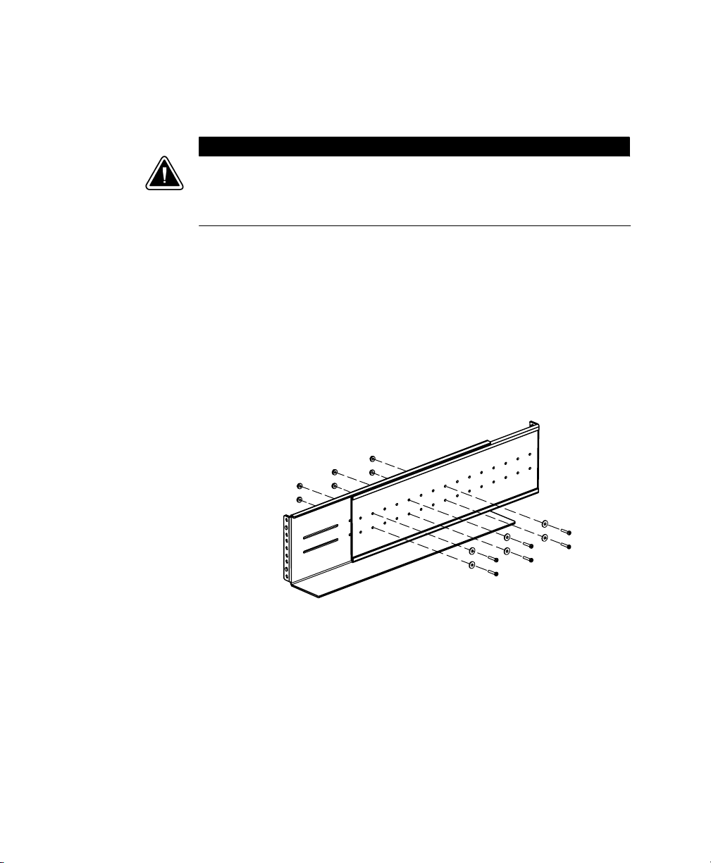
C A U T I O N
in your rack.
3. Loosely assemble the left and right rails using six #6−32
0.75"
screws, #6 flat−head washers, and #6−32 Keps nuts (see Figure 1).
Set aside the loosely assembled rails.
Figure 1. Assembling the Rails
2
EATON Powerware® 9170+ Rail Kit (9− and 12−Slot Cabinets) Installation Guide S 164201420 Rev C www.powerware.com
Page 5

RACKMOUNT INSTALLATION
4. Install six metal clip nuts (nine clip nuts for 12−slot cabinets) onto
each side flange along the front of the cabinet (see Figure 2).
NOTE DO NOT install metal clip nuts in the bottom cabinet section.
Metal Clip Nuts
Tab Slots
Tab Slots
Metal Clip Nuts
Tab Slots
Metal Clip Nuts
Figure 2. Metal Clip Nut and Tab Slot Locations
EATON Powerware® 9170+ Rail Kit (9− and 12−Slot Cabinets) Installation Guide S 164201420 Rev C www.powerware.com
3
Page 6

RACKMOUNT INSTALLATION
5. Install two rackmount ears (three for 12−slot cabinets) on each side
NOTE DO NOT install rackmount ears in the bottom cabinet section.
of the cabinet (see Figure 3).
Insert the two offset tabs on the rear edge of the ear into the
matching tab slots on the cabinet side frame (see Figure 2). Pivot
the ear forward until it is flush against the cabinet side frame.
Secure each ear with three 1/4−20
1/2" Phillips−head bolts; screw
the bolts into the metal clip nuts installed in Step 4.
Rackmount Ear
Rackmount Ear
Rackmount Ear
Figure 3. Rackmount Ears Installed
4
EATON Powerware® 9170+ Rail Kit (9− and 12−Slot Cabinets) Installation Guide S 164201420 Rev C www.powerware.com
Page 7

RACKMOUNT INSTALLATION
6. Select the proper holes in the rail that position the cabinet at the
desired location in the rack.
7. Secure the loosely assembled rail to the front and rear of the rack
with the supplied adapter plate in front of the mounting post using
two supplied #10−32
0.5" pan−head screws and #10 washers.
Repeat for the other side of the rack.
8. Tighten the rail assembly screws.
Adapter
Plate
Adapter
Plate
Pan−Head Screws and
#10 Washers
Pan−Head Screws and
#10 Washers
Figure 4. Securing the Rails
EATON Powerware® 9170+ Rail Kit (9− and 12−Slot Cabinets) Installation Guide S 164201420 Rev C www.powerware.com
5
Page 8

RACKMOUNT INSTALLATION
9. With one person lifting each side of the cabinet, position the cabinet
onto the two equipment rails (see Figure 5).
Carefully slide the cabinet into the equipment rack until the
rackmount ears of the cabinet are flush with the front vertical rails
of the rack. Verify that the holes in the ears align with the holes in
the rack.
Equipment Rail
Figure 5. Rails Holding UPS Cabinet
10. Secure the cabinet in the rack using #10−32 1/2" Torx® screws or
other appropriate customer−specified screws.
11. Follow the instructions in the UPS user’s guide to install the power
and battery modules.
6
EATON Powerware® 9170+ Rail Kit (9− and 12−Slot Cabinets) Installation Guide S 164201420 Rev C www.powerware.com
Page 9

Service and Support
If you have any questions or problems with the UPS, call your Local
Distributor or the Help Desk at one of the following telephone numbers
and ask for a UPS technical representative.
RACKMOUNT INSTALLATION
United States:
Canada: 1−800−461−9166 ext 260
All other countries: Call your local service representative
Please have the following information ready when you call the Help
Desk:
1−800−356−5737 or 1−919−870−3149
S Model number
S Serial number
S Version number (if available)
S Date of failure or problem
S Symptoms of failure or problem
S Customer return address and contact information
If repair is required, you will be given a Returned Material Authorization
(RMA) Number. This number must appear on the outside of the package
and on the Bill Of Lading (if applicable). Use the original packaging or
request packaging from the Help Desk or distributor. Units damaged in
shipment as a result of improper packaging are not covered under
warranty. A replacement or repair unit will be shipped, freight prepaid for
all warrantied units.
NOTE For critical applications, immediate replacement may be available. Call the Help
Desk
for the dealer or distributor nearest you.
EATON Powerware® 9170+ Rail Kit (9− and 12−Slot Cabinets) Installation Guide S 164201420 Rev C www.powerware.com
7
Page 10

RACKMOUNT INSTALLATION
8
EATON Powerware® 9170+ Rail Kit (9− and 12−Slot Cabinets) Installation Guide S 164201420 Rev C www.powerware.com
Page 11

Page 12

*164201420C*
164201420 C
 Loading...