

Page 1

02/20/2001
Powerware®9150
User’s Guide
8kVA-12.5kVA
www.powerware.com
Page 2

FCC Statement
The Powerware99150 UPS configurations vary. Some configurations may or may not be classified by the Federal
Communications Commission (FCC) as a Class A device. If your Powerware 9150 unit is classified by these standards, the
corresponding informationapplies:
Class A
NOTE This equipmenthas been tested and found to comply withthelimits for a C lass A digital device, pursuantto Part
15 of the FCC Rules. These limits are designed to provide reasonable protection against harmful interference when the
equipment is operated in a commercial environment. This equipment generates, uses, and can radiate radio frequency
energyand, if not installed and used inaccordance withthe instruction manual, may cause interference toradio
communications. Operation of this equipment in a residential area is likely to cause interference in which case the user will
be required to correcttheinterference at his own expense.
Powerware and OnliNetare registered trademarks and ConnectUPSis a trademark of PowerwareCorporation.
.
Copyright 1999 Powerware Corporation, Raleigh, NC. All rights reserved. No part of this document may be reproduced
in any way without the express writtenapproval of PowerwareCorporation.
Page 3

Table ofContents
TABLE OF CONTENTS
1 Introduction 1....................................................
UPSModel and BatteryConfigurations 2..............................................
LoadRequirements 2.........................................................
BatteryTimes 3.............................................................
2 Safety Warnings 5.................................................
Sikkerhedsanvisninger 7.........................................................
Belangrijke Veiligheidsinstructies 8..................................................
Tärkeitäturvaohjeita 9..........................................................
ConsignesdeSécurité 10.........................................................
WichtigeSicherheitsanweisungen 11.................................................
Importantiistruzionidisicurezza 12..................................................
Viktig Sikkerhetsinformasion 13.....................................................
RegulamentosdeSegurança 14.....................................................
Requisitosdeseguridad 15........................................................
Viktig säkerhetsinformation 16......................................................
3 Installation 17.....................................................
UPSStorage 17................................................................
UPSSetup 18..................................................................
FloorLoading 18..............................................................
SeismicMounting 19..........................................................
SelectinganInstallationOption 20...................................................
UPSInstallation 20..............................................................
UPSwithOptionalPDM Installation 25................................................
ExternalBatteryCabinet Installation 30...............................................
UPSStartup 33.................................................................
BypassStartup 33............................................................
NormalMode Startup 34.......................................................
UPSStartup on Battery 35......................................................
ConfiguringVoltageandFrequency 36................................................
AutomaticConfigurationMode 36.................................................
ManualConfigurationMode 37...................................................
Powerware®9150 User’sGuide:www.powerware.com
i
Page 4

Table ofContents
4 Operation 39......................................................
ControlPanel Functions 39.........................................................
NEEDNEW LOGO 39.............................................................
OperatingModes 41.............................................................
NormalMode 42.............................................................
BypassMode 42.............................................................
BatteryMode 42.............................................................
UPSShutdown 43...............................................................
UsingtheMaintenance Bypass Switch 44..............................................
Computerand AlarmConnections 46.................................................
NEEDNEW LOGO 46.............................................................
HardwareInstallation 46.......................................................
RS-232SerialData Interfaces 47..................................................
IsolatedAlarmRelayInterface 49.................................................
RemoteEmergencyPower-offInput 50..............................................
EfficiencyOptimizerFunction 50.....................................................
5 Specifications 51..................................................
Powerware9150 TechnicalSpecifications 51...........................................
Powerware9150 ModelSpecifications 52.............................................
PhysicalSpecifications 53.........................................................
EnvironmentalandSafety Specifications 54............................................
ExternalBatteryCabinet Specifications 54.............................................
6 Troubleshooting 55.................................................
Silencing the Alarm 56...........................................................
ServiceandSupport 57...........................................................
Upgrading 57..................................................................
ii
Powerware®9150 User’sGuide:www.powerware.com
Page 5
CHAPTER 1
INTRODUCTION
The Powerware99150 is a double-conversion, online uninterruptible
power supply(UPS)for protecting computer systemsand other
intelligent devices.
The UPS providesa steady,well-regulated power supplyfor your
computing andcommunications equipment,while protectingit from the
frequent irregularitiesthat areinherent in commercially available power.
Voltage spikes,power surges, brownouts, and power failures have the
potentialto corruptcriticaldata, destroyunsavedwork sessions, and in
some instances,damage expensivehardware.
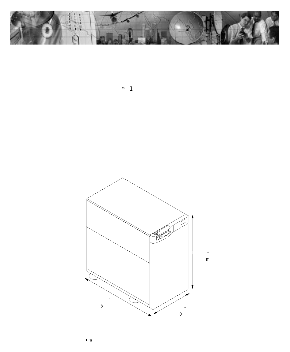
Withthe Powerware 9150, youcan safely eliminate the effects of
electricalline disturbancesand guard the integrity of yoursystemsand
equipment. Figure 1 showsthe Powerware 9150 UPS.
29.72
2
(755 mm)
Figure1. The Powerware 9150 UPS
Powerware®9150 User’sGuide:www.powerware.com
15.75
2
(400 mm)
28.23
2
(717 mm)
1
Page 6

Introduction
UPS Model and Battery Configurations
There are two important considerations whenselectingthe UPS model
and battery configuration to properly safeguard your equipment:
:
The UPS outputpower rating(VA) shouldbe specified according to
the total power demand of the equipment to be protected.Some
marginshould be allowed for pote ntial expansion of the protected
system,and forpossible inaccuracy in calculating or measuring the
actualpower requirement.
:
The battery should be sized according to the desired backup time.
The backup time is longer if the load is less than the nominal power
rating of the UPS.
Load Requirements
Determine the total load requirements, in volt-amperes (VA), of the
equipment to be protectedby the UPS.The UPSload should not exceed
the UPS rating.To determine the total loadrequirements:
1. Obtainthe load ratings fromeither thenameplate oroperator’s
manual of the equipment to be protected by the UPS. The
ratings are listed in either watts (W),amperes or amperes max
(A), or volt-amperes.
2. If the ratingis in watts, multiply by 1.4 to obtain the VA
requirement (this isthe typicalrelationship betweenwatts and
volt-ampere ratings in most computing equipment).
If therating isin amperesor amperesmax, multiply by the
inputvoltage to obtain the VA requirement.
3. Add all of the resultant VA ratings together to obtain the total
load requirementsof the equipment tobe protected (see
Figure 2).
3 COMPUTERS 3 MONITORS EXTERNAL
300 WATTS
EACH
3 x 300 WATTS X 1.4 = 1260 VA 3x2AMPSx240V = 1440 VA 50 VA
1260 VA + 1440 VA + 50 VA = 2750 VA (Total Load Requirements)
2AMPS
EACH 50 VA
MODEM
Figure 2. Volt-Amperes Calculation Example
2
Powerware®9150 User’sGuide:www.powerware.com
Page 7

Introduction
If thetotal load requirementsof the equipment exceeds the capacity of
the UPS, youmust eitherreduce the numberof pieces of equipment, or
use a UPS witha largerload capacity.
NOTE Line-to-neutralloads(100V- 127V)shouldbe balancedbetweenL1/Aand
L2/B.
Whendeciding on which pieces of equipment to removefrom theUPS,
select equipment thathas a lowerpriorityfor power protection.
Computers, monitors, and modems typically have a higher priority
becausethey couldbe processing or transmitting data when a power
outage occurs.
Battery Times
The Powerware9150 UPS has internalbatte ries with run times up to
17 minutes. If additional run time is required, optional externalbattery
cabinets(EBCs)can be purchased. There are two EBCmodels available:
EBC-48and EBC-96.The EBC-48 model contains48 batteriesand the
EBC-96 model contains96 batteries. The followingtable shows
approximate battery times for both internalbattery models and the
optional EBCconfigurations.The times shown in the EBC rows are
cumulative and include the internal battery time.
Powerware 9150Approximate Battery Times (in Minutes atFull Load)
UPSwith
Internal Batteries
1 EBC-48 Cabinet 41 31 23
1 EBC-96 Cabinet 69 52 40
2 EBC-96Cabinets 133 101 77
3 EBC-96Cabinets 206 157 119
4 EBC-96Cabinets 284 217 165
5 EBC-96Cabinets 368 281 213
*EBCs are notavailable for the32-battery model. Refer to the serial nameplate; ifDC voltage
on the nameplate is192V,EBCs cannot be used.Touse EBCs, DC voltage must be 288V.
Powerware®9150 User’sGuide:www.powerware.com
Model8kVA Model10kVA Model 12.5kVA
32 Batteries* 10 8
48 Batteries
17 13 9
3
Page 8

Introduction
If a powerfailureoutlaststhe backup time,the UPSshuts down in order
to prevent a total discharge of the battery. When utilityis restored, the
UPSstarts automatically, providingpower to thecritical load and
charging the battery bank.
4
Powerware®9150 User’sGuide:www.powerware.com
Page 9

CHAPTER 2
SAFETY WARNINGS
The onlyuser operations permitted are:
:
Starting up and shutting down the UPS
:
Operatingthe userinterface
:
Connecting data interface cables
:
Monitoring theUPS withpower management software
Onlyqualifiedservice personnel(suchas a licensed electrician) shouldperformthe
UPSinstallationandinitialstartup.Riskof electricalshock.
Theseoperationsmust be performed accordingto the instructionsin
this manual. During any of these operations, you must perform only the
listed operations.Any deviation from the instructions could be
dangerous.
IMPORTANT SAFETY INSTRUCTIONS
SAVE THESEINSTRUCTIONS. Thismanualcontainsimportantinstructionsthatyou
shouldfollowduring installationand maintenance ofthe UPS andbatteries.Please
read all instructionsbefore operatingthe equipment andsavethis manual forfuture
reference.
WARNING
Powerware®9150 User’sGuide:www.powerware.com
5
Page 10

Safety Warnings
DANGER
ThisUPScontainsLETHAL VOLTAGES. All repairs and serviceshouldbe performed
byAUTHORIZED SERVICE PERSONNEL ONLY. There are NO USER
SERVICEABLE PARTS insidetheUPS.
CAUTION
:
Outputovercurrentprotection and disconnectswitch mustbe providedbyothers
(seetable on page21).
:
To reducethe riskoffire,connect only toa circuitprovided with 70amperes
maximumbranchcircuitovercurrentprotectionin accordance with theNational
ElectricalCode, ANSI/NFPA70 (seetableon page21).
:
Batteriescanpresent ariskof electricalshockor burnfrom high shortcircuit
current.Observeproper precautions.Servicingshouldbe performedbyqualified
servicepersonnelknowledgeableofbatteries and requiredprecautions.Keep
unauthorizedpersonnelaway from batteries.
:
Proper disposalof batteriesisrequired.Refer to yourlocalcodesfor disposal
requirements.
:
ThisUPScontainsits own energy source(batteries). TheUPSoutput may carrylive
voltageevenwhen theUPS is not connectedto anACsupply.
:
Neverdisposeofbatteriesinafire.Batteriesmayexplodewhenexposedtoflame.
:
To reducethe riskoffire or electricshock,install this UPS ina temperature and
humiditycontrolled,indoorenvironment,freeofconductivecontaminants.Ambient
temperaturemust not exceed104F(40C).Donot operatenear wateror
excessive humidity (95% max).
6
Powerware®9150 User’sGuide:www.powerware.com
Page 11

Sikkerhedsanvisninger
DenneUPS (ubrudt strømforsyning) indeholderLIVSFARLIGSPÆNDING.Al reparation
og servicebør KUNforetagesaf AUTORISERET SERVICEPERSONALE.Derer INGEN
DELEiUPS’en,hvorpå en BRUGERBØRFORETAGE SERVICE.
:
Batterierkan give risiko tilelektrisk stødellerforbrænding fra stærk
kortslutningsstrøm. Observer korrekte forholdsregler.
:
Korrektafkastningaf batterier kræves. HenvendDemtilderes lokale lovem.h.t.
affaldsreguleringer.
:
DenneUPS indeholder en selvforsynende energikilde(batterier).
Udgangskontakternekanoverførestromførende spænding, når UPS’enikkeer
forbundet med envekselstrømsforsyning.
:
Brændaldrigbatterierne.Batteriernekaneksplodere,nårdeudsættesforflammer.
:
InstallerUPS’eniet temperatur- og fugtighedskontrolleret miljø frit for
konduktiverendematerialefor, atreducere risikoenfor brandog elektrisk stød.
Omgivelsestemperaturenmåikkeoverskride40C.Betjenikke udstyrerinærheden
af vand ellerurimeligfugtighed(95%maksimum).
Safety Warnings
FARE
ADVARSEL
Powerware®9150 User’sGuide:www.powerware.com
7
Page 12

Safety Warnings
Belangrijke Veiligheidsinstructies
DezeUPS bevat LEVENSGEVAARLIJKE ELEKTRISCHE SPANNING.Allereparaties en
onderhoud dienen UITSLUITEND DOOR ERKENDSERVICEPERSONEELte worden
uitgevoerd.Erbevinden zich GEEN ONDERDELEN inde UPSdieDOOR DEGEBRUIKER
kunnenworden GEREPAREERD.
:
Batterijenkunnengevaar voor elektrische schokofbrandwonden veroorzakenals
gevolgvanhoge kortsluitstroom. Volgde desbetreffendeaanwijzingenop.
:
Debatterijenmoetenopdejuistewijze worden opgeruimd.Raadpleeghiervooruw
plaatselijke voorschriften.
:
DezeUPSbevatzijneigenenergiebron (batterijen).De uitvoercontactdozenkunnen
onder spanning staan wanneerde UPSnietop eenwisselstroom voedingis
aangesloten.
:
Nooitbatterijenin hetvuur gooien. De batterijenkunnenontploffen.
:
Teneinde dekans op brandof elektrische schokteverminderendientdeze UPS in
een gebouw mettemperatuur-en vochtigheidregelingte worden geïnstalleerd,
waargeengeleidendeverontreinigingenaanwezigzijn.Deomgevingstemperatuur
mag40Cnietoverschrijden.Niet gebruikenin debuurtvan water ofbijzeerhoge
vochtigheid(max.95%).
GEVAAR
OPGELET
8
Powerware®9150 User’sGuide:www.powerware.com
Page 13

Tärkeitä turvaohjeita
Tämä UPS sisältää HENGENVAARALLISIA JÄNNITTEITÄ.Kaikkikorjaukset jahuollot
on jätettävä VAINVALTUUTETUNHUOLTOHENKILÖSTÖN TOIMEKSI. Tämä UPS ei
sisällä MITÄÄNKÄYTTÄJÄN HUOLLETTAVIA OSIA.
:
Akustosaattaaaiheuttaa sähköiskunvaaran tai syttyätuleenmikäliakusto
kytketäänoikosulkuun. Noudataasianmukaisia ohjeita.
:
Akustotäytyyhävittääsäädöstenmukaisella tavalla.Noudatapaikallisia
määräyksiä.
:
TämäUPS sisältääoman energialähteen(akuston). Ulostulorasioissavoiolla
jännite,kunUPS ei oleliitettynä verkkojännitteeseen.
:
Äläkoskaanheitäakkujatuleen. Ne voivaträjähtää.
:
VähentääksesitulipalonjasähköiskunvaaraaasennatämäUPS sisätiloihin,joissa
lämpötilajakosteuson säädettävissäja joissaei olesähköäjohtavia
epäpuhtauksia.Ympäristön lämpötilaeisaa ylittää 40C.Äläkäytä lähellä vettä
tai liian kosteissa oloissa (95 %maksimi).
Safety Warnings
VAARA
VARO
Powerware®9150 User’sGuide:www.powerware.com
9
Page 14

Safety Warnings
Consignes de Sécurité
Consignes Importantes De Sécurité - Conserver Ces Instructions
Cette Notice Contient Des Consignes Importantes De Sécurité
CetUPS contient destensionsmortelles.Toute opérationd’entretienet deréparation
doit être effectuée UNIQUEMENT PARUN PERSONNEL QUALIFIÉ AGRÉE. L’UPS n’a
AUCUNEPIÈCE RÉPARABLEPARL’UTILISATEUR.
:
Unebatterie peut présenterun risquede choc électrique ou de brûlure parun
transfertd’énergie ou uncourt-circuit.Prendreles précautions nécessaires.
:
Unemiseau rebutréglementairedes batteries estobligatoire.Consulterles
règlementsen vigueurdansvotrelocalité concernantlamiseaurebutdebatteries.
:
CetUPS contient sapropre source d’énergie(batteries). Lesprisesdesortie
peuventêtre soustensionmêmelorsque l’UPSn’est pas branchésurle secteur.
:
Ne jamaisse débarrasser debatteriesen lesincinérant.Ellesrisquentd’exploser
lorsqu’elles sontexposéesà une flamme.
:
Afinde réduire lesrisquesd’incendieetde chocélectrique,installer l’UPS
uniquementdansun espaceintérieuràtempératureethumiditécontrôléesetsans
matérielconducteur. La températureambiante ne doitpas dépasser 40C.Ne pas
utiliser à proximité d’eau ou dansune atmosphèreexcessivement humide
(95 %max).
ATTENTION!
DANGER!
10
Powerware®9150 User’sGuide:www.powerware.com
Page 15

Wichtige Sicherheitsanweisungen
Lebensgefahr!DieseUSVenthält TÖDLICHESPANNUNGEN! Alle Reparatur- und
WartungsarbeitensolltenNURVONAUTORISIERTEM WARTUNGSPERSONAL
durchgeführtwerden. In dieserUSVbefindensichKEINE VOM BENUTZERZU
WARTENDEN TEILE.
:
Batterienkönnen aufgrund vonKurzschlußhochstrom Elektroschocks oder
Verbrennungenverursachen.EntsprechendeAnleitungenbefolgen.
:
DieBatterienmüssenordnungsgemäß weggeworfen werden.
Entsorgungsanweisungen sindden örtlichen Vorschriftenzuentnehmen.
:
DieseUSVenthältihre eigeneStromquelle(Batterien).Anden
Ausgangssteckdosen kann Spannunganliegen,selbstwenn die USVnichtan eine
Wechselspannungsquelleangeschlossenist.
:
Batterienniemalsverbrennen,da sieexplodierenkönnen.
:
UmdieBrand-oderElektroschockgefahrzu verringern,diese USV nur inGebäuden
mit kontrollierter Temperatur und Luftfeuchtigkeit installieren, in denen keine
leitendenSchmutzstoffenvorhandensind.DieUmgebungstemperaturdarf 40C
nichtübersteigen.DieUSVnicht in derNähe vonWasseroderin extrem hoher
Luftfeuchtigkeit (max.95%) betreiben.
Safety Warnings
WARNUNG
VORSICHT!
Powerware®9150 User’sGuide:www.powerware.com
11
Page 16

Safety Warnings
Importanti istruzioni di sicurezza
LaTENSIONEcontenuta in questogruppo statico dicontinuitàè LETALE. Tuttele
operazionidiriparazionee dimanutenzionedevono essereeffettuate
ESCLUSIVAMENTE DA PERSONALE TECNICO AUTORIZZATO.All’interno del gruppo
staticodicontinuitàNON vi sonoPARTI RIPARABILIDALL’UTENTE.
:
Lebatteriepossonopresentarerischiodiscossaelettricaodiustioniprovocateda
altacorrente dovuta acorto circuito. Osservare leappositeistruzioni.
:
Lebatterie devono esseresmaltiteinmodo corretto.Peri requisitidi smaltimento
fare riferimento alle disposizionilocali.
:
Questogruppo statico di continuitàcontieneuna fonte dienergia autonoma (le
batterie).Leprese di uscitapossonocondurretensione energizzata quando il
gruppo staticodi continuità non è collegatoconuna fontedi alimentazionea
correntealternata.
:
Nongettare mai lebatterienelfuocopoichèpotrebbero esplodereseespostealle
fiamme.
:
Per ridurre ilrischio diincendioo discossaelettrica,installare ilgruppo statico di
continuitàinun ambienteinternoa temperaturaed umidità controllata, privodi
agenticontaminanticonduttivi.Latemperatura ambiente nondeve superare i
40C.Non utilizzare l’unitàinprossimitàdiacqua o inpresenza di umidità
eccessiva (95% max).
PERICOLO
ATTENZIONE
12
Powerware®9150 User’sGuide:www.powerware.com
Page 17

Viktig Sikkerhetsinformasion
DenneUPS’eninneholder LIVSFARLIGE SPENNINGER.Allreparasjon og servicemå
kun utføres avAUTORISERT SERVICEPERSONALE.BRUKERE KAN IKKE UTFØRE
SERVICEPÅNOEN AVDELENEi UPS’en.
:
Batterierkan forårsake elektriskestøt eller forbrenningpå grunn avhøy
kortslutningsstrøm. Følg instruksene.
:
Batteriermå fjernes påkorrektmåte. Se lokaleforskriftervedrørendekravom
fjerningav batterier.
:
DenneUPS’enhar enegen energikilde (batterier).Stikkontaktene kanvære
strømførendeselvom UPS’en ikke er tilsluttetenvekselstrømforsyning.
:
Kastaldribatterier i flammer, da de kan eksplodere, hvisdeutsettes for åpenild.
:
Foråreduserefare for brannellerelektriske støt, børdenne UPS’eninstalleresiet
innendørsmiljø med kontrollert temperatur og luftfuktighetsom er frittfor
ledende,forurensendestoffer.Romtemperaturenmåikkeoverskride40C.Denmå
ikkebrukesinærheten avvanneller ved megethøy luftfuktighet(95% maks.).
Safety Warnings
FARLIG
FORSIKTIG
Powerware®9150 User’sGuide:www.powerware.com
13
Page 18

Safety Warnings
Regulamentos de Segurança
OUPS contém VOLTAGEM MORTAL.Todososreparose assistênciatécnicadevemser
executadosSOMENTEPORPESSOALDAASSISTÊNCIATÉCNICAAUTORIZADO. Não
há nenhuma PEÇAQUEPOSSASER REPARADA PELOUSUÁRIO dentrodo UPS.
:
Asbateriaspodem apresentar oriscode choqueelétrico,ou queimaduras
provenientesde alta correntede curto-circuito.Observeasinstruçõesadequadas.
:
Sigaosdevidosregulamentosao desfazer-se das baterias.Consulte oscódigosdo
localpara maiores informaçõessobre osregulamentosde descarte deprodutos.
:
EsteUPScontémsuaprópriafonte de energia(baterias).Osreceptáculos desaída
podemconter voltagemativaquandoo UPSnão se encontraconectadoa uma
fonte de alimentaçãodecorrente alternada.
:
Nuncase desfaça dasbateriasjogando-asno fogo.Háriscode explosãoquando
expostasàchamas.
:
Para reduzir oriscode incêndiosou choqueselétricos,instale o UPSem ambiente
internocom temperatura eumidade controladas e livresdecontaminadores
condutíveis.Atemperaturaambientenãodeveexceder40C.Não opero-opróximo
a água ouem umidadeexcessiva (máx:95%).
CUIDADO
PERIGO
14
Powerware®9150 User’sGuide:www.powerware.com
Page 19

Requisitos de seguridad
EsteUPS(suministrode alimentaciónpermanente)contieneVOLTAJESLETALES.Todas
lasreparacionesyel servicio técnico deberán serrealizadospor PERSONAL DE
SERVICIO TECNICO AUTORIZADO SOLAMENTE. Este UPSNO CONTIENE PARTESQUE
PUEDAN SER REPARADASPOR EL USUARIO.
:
Lasbateríaspuedenpresentarunriesgode descargas eléctricaso de quemaduras
debidoa laaltacorriente de cortocircuito. Presteatencióna lasinstrucciones
correspondientes.
:
Esnecesariodeshacersede lasbateríasadecuadamente.Consultelas
disposiciones localespara conocercuálessonlos requisitospertinentes.
:
EsteUPS contiene su propiafuente deenergía (baterías).Es posible que los
receptáculosdesalidatengan tensióncuandoel UPS noestá conectado a un
suministro de corriente alterna (CA).
:
Nuncaarrojelasbateríasalfuegoyaque pueden explotarcuandoson expuestasa
las llamas.
:
Paradisminuirelriesgodeincendioo descargas eléctricas,instale esteUPSen un
ambienteinteriora temperaturay humedad controladas,ysincontaminantes
conductores.Latemperatura ambiente nodebe superarlos40C.No lohaga
funcionarcercadel agua o de condicionesde humedad excesivas(95%como
máximo).
Safety Warnings
PELIGRO
PRECAUCIÓN
Powerware®9150 User’sGuide:www.powerware.com
15
Page 20

Safety Warnings
Viktig säkerhetsinformation
DennaUPS-enhet innehåller LIVSFARLIG SPÄNNING.ENDAST AUKTORISERAD
SERVICEPERSONAL får utföra reparationer ellerservice.Det finnsingadelar som
ANVÄNDAREN KANUTFÖRASERVICEPÅinutiUPS-enheten.
:
Batteriernakangeelektriskastötarellerbrännskadorfrån hög kortslutningsström.
Följ tillämpliga anvisningar.
:
Batteriernamåstekasserasenligtanvisningarnai lokal lagstiftning.
:
DennaUPS-enhethar en egen energikälla(batterier).Deutgåendekontakternakan
varaspänningsförandenär UPS-enheten inteäranslutentillenväxelströmsenhet.
:
Användabatterierfår aldrigbrännasupp. Dekanexplodera.
:
Minskarisken förelektriska stötargenomatt installera denna UPS-enhetinomhus,
därtemperaturochluftfuktighetär kontrolleradeochdäringaledandeföroreningar
förekommer. Omgivandetemperatur fårej överstiga 40Celcius. Använd inte
utrustningennära vatten ellervidhög luftfuktighet (max95%).
FARA
VIKTIGT
16
Powerware®9150 User’sGuide:www.powerware.com
Page 21

CHAPTER 3
INSTALLATION
The followingsection describes UPS storage requirements, UPSsetup,
and the installation and startup of the UPS. The instructions are
intended for the chiefoperator/system supervisor,electricalconsultants,
and installationelectricians.Local regulations and electricalcode must
be followed in the UPS installation.
UPS Storage
Whenstoringthe UPSand optionalcabinets,the following
requirements should be met:
:
The UPS should be stored in the original packing and shipping
carton.
:
Avoid temperature and humidityextremes. To maximize battery life,
the recommended storage temperature is 59F(15C) to 77F
(25C).
:
The equipment mustalways be protected from moisture and weather.
:
Forlong termstorage, the UPS batteries shouldbe chargedfor at least
8 hoursevery 6 months to maintainthe battery charge.
Powerware®9150 User’sGuide:www.powerware.com
17
Page 22
Installation
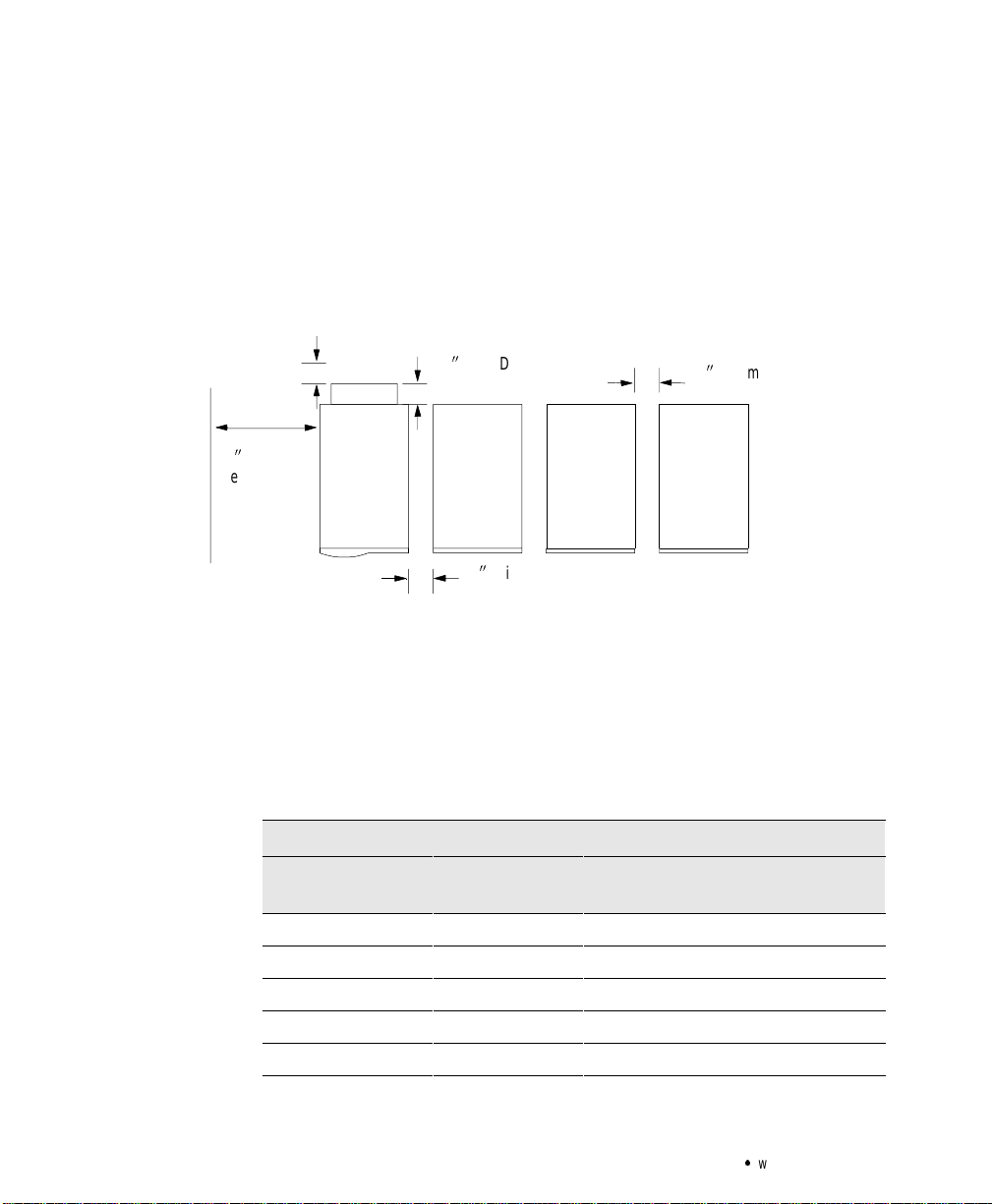
UPS Setup
PDM Cord Connections
When the UPS is in use, allow a minimum of 4 inches (100 mm) for
ventilationon both sides, top,and rear of the UPS (see Figure 3). When
the UPS is serviced, allow 30 inches (762 mm) for removal of the UPS
left panel. Maintain clearancein front of the UPSfor useroperations.If
you have an optional Power Distribution Module (PDM), allow
additional space in therear forthe PDMcord connections.
5.0
2
30
2
Clearance
for Service
PDM Depth
PDM
UPS EBC EBC EBC
42Minimum Spacing
Around UPS
32Minimum Spacing
Around EBC
18
Figure 3. Spacing Requirements (TopView)
Floor Loading
When planning the installation, consider the UPS weight for floor
loading. The strength of the installation surfacemust be adequatefor
point and distributed loadings. The weights are shown in the following
table.
StandardModelFloorLoadings
Powerware 9150 Maximum
Weight(lb)
Model 8 kVA 550 12.5 170
Model 10 kVA 550 12.5 170
Model 12.5 kVA 550 12.5 170
EBC-48 468 9.6 130
EBC-96 765 17.4 236
PointLoading
Powerware®9150 User’sGuide:www.powerware.com
(lb/in
2
)
Distributed
Loading(lb/ft
2
)
Page 23

5.24
2
(133 mm)
17.48
(444 mm)
Seismic Mounting
The Powerware9150 has a seismic mountingoption. The UPSis
shippedwith floormounting brackets instead of the leveling feet. You
will need 3/82hardware (4 boltsper cabinet)to complete the
installation. See Figure 4 for a detailed drill and mounting pattern.
PDM
2
UPS EBC EBC
Installation
17.32
2
(440 mm)
19.75
2
(501.6 mm)
Figure 4. Seismic Mounting Pattern
Powerware®9150 User’sGuide:www.powerware.com
18.75
2
(476.2 mm)
Typical
19
Page 24

Installation
Selecting an Installation Option
In additionto the standard Powerware 9150, the UPS has an optional
PDM. Use the following flow chart to decide which installation option
is right for you.
UPS Installation
Do you have an
optional PDM?
No
See the following
section, “UPS
Installation.”
Yes
See“UPS with
Optional PDM
Installation”
on page 25.
The Powerware9150 has the followingpower connections:
:
2-phase(L1/A and L2/B), neutral,and ground connectionfor
rectifier/bypass input
:
2-phase(L1/A and L2/B), neutral,and ground connectionfor load
output
The nominal input/outputvoltages are:
:
100/200, 110/220,or 120/240 Vac with 180phase displacement
:
120/208 or 127/220 Vac with120phase displacement
20
WARNING
Onlyqualifiedservice personnel(suchas a licensed electrician) shouldperformthe
UPSinstallationandinitialstartup.Riskof electricalshock.
Powerware®9150 User’sGuide:www.powerware.com
Page 25

Installation
Use the following procedure to connect utility power and load to the
UPS:
1. Verify that the electrical connections to the installation site have
been properly installed.Compare thecircuit breaker ratings and
cable sizesto the onesshownin the terminationstable on
page 24.
2. A user-supplied,readily-accessible, disconnection devicemust
be incorporated in both the input and output wiring (see the
following breakerratings).
Powerware 9150
Model 8 kVA 50A 50A
Model 10 kVA 60A 60A
Model 12.5 kVA 70A 70A
SuggestedBreakerRatings
Input Output
3. Switch off utility power to the distribution point where the UPS
will be connected. Be absolutely sure there is no power.
4. Remove the front panel. Lift from the bottom of the panel and
then pull out (see Figure 5).
5. Remove the left sidepanel of theUPS by unscrewing the two
screws and pulling the panel (see Figure 5).
Powerware®9150 User’sGuide:www.powerware.com
21
Page 26

Installation
22
Left Panel Screws
Figure 5. Removing the UPS Panels
Powerware®9150 User’sGuide:www.powerware.com
Page 27

Installation
6. Verify that the UPS battery breakerCB1 and optional CB2 are in
the OFF position (see Figure 6).
UPSON/OFFSwitch
and Indicators
ON
Input
Conduit
Access
Output
Conduit
Access
OFF
CB2
T erminal
Block
Maintenance
Bypass Switch
F1
Battery
Neutral
Fuse
CB1
Internal
Battery
Breaker
(Optional)
External
Battery
Breaker
Figure 6. UPS Front and Side View
7. Hardwire the input (TB1-1 through TB1-4) and output (TB1-6
through TB1-9) terminations forthe UPS. See the following
hardwired terminations tablefor specifications. See Figure7 for
a detailed view of the terminal blocks.
NOTE The input neutralmustbe wiredfor proper operation.
8. Determine yourequipment’s grounding requirements according
to yourlocal electrical code.
Powerware®9150 User’sGuide:www.powerware.com
23
Page 28

Installation
p
1-3/4accessholeor
p
1-3/4accessholeor
Powerware 9150Hardwired T erminations
WireFunction Terminal
Position*
Input
Output
*All terminal wire sizeratings are 8 - 4AWG, exceptTB1-4 and TB1-9 are 8 - 1/0.
**Use 75
Ground TB1-1 8AWG
L1/A TB1-2
L2/B
Neutral
Ground TB1-6 8AWG
L1/A TB1-7 4AWG
L2/B
Neutral
C copper wire. Suggested wire size isbased on 120/208 full load ratings appliedto NEC Code Table310-16.
TB1-3
TB1-4 2AWG
TB1-8 4AWG
TB1-9 2AWG
UpstreamCircuit
Breaker
70A
70A
SuggestedWire
NOTE Proper phase rotationmustbe observed.
123 4 678 9
Size**
4AWG
4AWG
Conduit
Connection
(EntrySize)
1-3/42access hole for
1-1/42conduit
1-3/42access hole for
1-1/42conduit
Ground L1/A L2/B N Ground L1/A L2/B N
Input Output
Figure 7. Hardwired Terminal Blocks
24
Powerware®9150 User’sGuide:www.powerware.com
Page 29

9. Reinstall the UPSleft side panel. (Do not reinstall the front
panel at this time.)
10. Lower the leveling feet to prevent the UPS from rolling (does
not apply for seismic mounting installations).
11. If youhave additionalbattery cabinets, continue to “External
Battery Cabinet I nstallation” on page 30. Otherwise,skip to
“UPS Startup”on page 33.
UPS with Optional PDM Installation
Onlyqualifiedservice personnel(suchas a licensed electrician) shouldperformthe
UPSinstallationandinitialstartup.Riskof electricalshock.
Use the following procedure to install the PDM:
1. Switch off utility power to the distribution point where the UPS
will be connected. Be absolutely sure there is no power.
2. Remove the front panel. Lift from the bottom of the panel and
then pull out (see Figure 8).
3. Remove the left sidepanel of theUPS by unscrewing the two
screws and pulling the panel (see Figure 8).
Installation
WARNING
Powerware®9150 User’sGuide:www.powerware.com
25
Page 30

Installation
26
Left Panel Screws
Figure 8. Removing the UPS Panels
Powerware®9150 User’sGuide:www.powerware.com
Page 31

Output
Conduit
Landing
Installation
4. Verify that the UPS battery breakerCB1 and optional CB2 are in
the OFF position (see Figure 9).
ON
OFF
CB2
T erminal
Block
F1
Battery
Neutral
Fuse
CB1
Internal
Battery
Breaker
(Optional)
External
Battery
Breaker
Figure 9. Connecting PDM Wiring to TerminalBlock
5. Remove the lower rear panel of theUPS by unscrewing the six
screws. Save the screws for reuse; the panelis no longer needed
(see Figure 10).
6. Mount the PDMchassis inthe spot previouslyoccupied by the
rear panel. The wires exiting the PDM should be close to the
output conduit landing on the UPS (see Figure 10).
Powerware®9150 User’sGuide:www.powerware.com
Maintenance
Bypass
Switch
27
Page 32

Installation
Screws from
UPS panel; 3 on
each side
reused for PDM
WireCoverfor
Output Conduit
Landing
28
Figure 10. Mounting the PDM to UPSRear Panel
7. Insert the bushing (provided with the PDM packaging) into the
output conduit landing.
8. Hardwire the input (TB1-1 through TB1-4) terminations for the
UPS. See the following hardwired terminations table for
specifications. See Figure11 for a detailedview of the terminal
blocks.
9. Insert the wires from the PDMinto the output conduitlanding
and connect to the UPSterminalblock according to the
following table.
Powerware®9150 User’sGuide:www.powerware.com
Page 33
Powerware 9150Hardwired Terminations for Optional PDM
Termina
l
Upstrea
m
ConduitConnection
1-3/4accessholeor
1-3/4accessholeor
Installation
WireFunction
Input
Ground
L1/A TB1-2
L2/B
Neutral
OutputforPDM WireColor
Ground TB1-6 Green/Yellow
L1/A TB1-7 Black
L2/B
Neutral
*All terminal wire sizeratings are 8 - 4AWG, exceptTB1-4 is 8-1/0.
**Use 75
C copper wire. Suggested wire size isbased on 120/208 full load ratings appliedto NEC Code Table310-16.
Terminal Upstream
Position*
TB1-1 8AWG
TB1-3
TB1-4 2AWG
TB1-8 Red
TB1-9 White
CircuitBreaker
70A
70A
SuggestedWireSize**
4AWG
4AWG
NOTE Proper phase rotationmustbe observed.
123 4 678 9
ConduitConnection
(EntrySize)
1-3/42access hole for
1-1/42conduit
1-3/42access hole for
1-1/42conduit
Ground L1/A L2/B N Ground L1/A L2/B N
Input Output
Figure 11. Hardwired TerminalBlocks
Powerware®9150 User’sGuide:www.powerware.com
29
Page 34

Installation
10. Connectthe wirecover to thePDM using the twoscrews
provided(see Figure 10).
11. Reinstall the UPS left side panel.(Do notreinstall the front
panel at this time.)
12. Lower the levelingfeet to prevent the UPSfrom rolling (does
not apply for seismic mounting installations).
13. If youhave additionalbattery cabinets, continue to the
following “External Battery Cabinet Installation” procedure.
Otherwise,skip to “UPS Startup” on page 33.
External Battery Cabinet Installation
The Powerware9150 UPS has either 32 or 48 internal batteries. EBCs
are available for the 48-battery model. Refer to the UPS serial nameplate;
the DC voltage on the nameplate must be 288V to add EBCs.
The internal battery charger can supportadditionalEBCs; however,
additional battery capacityalso extendsthe recharge time.
NOTE Aservicerepresentativemustchange theBatterySize parameter inthe
nonvolatilememorytoreflect the correctnumber of batterystringsafter installing
EBCs.
30
WARNING
Onlyqualifiedservice personnel(suchas a licensed electrician) shouldperformthe
UPSinstallationandinitialstartup.Riskof electricalshock.
Use the following instructions for installing an EBC with the 48-battery
UPS:
1. If theUPS is operating, turnthe Maintenance Bypassswitch to
the BYPASS position and turnoff the UPS ON/OFF switch(the
position).See Figure 6 on page 23.
2. Verify thecircuit breakers on the UPSare in the OFF position.
3. Facing the UPS, place the battery cabinet to the right of the
UPS. Confirm the DC voltage on the nameplate of the UPS and
EBC is288V.
4. Remove the frontpanel of each EBC. Lift from thebottom of
the panel and then pull out (see Figure 12).
Powerware®9150 User’sGuide:www.powerware.com
Page 35

CB2
CB1 Safety
Wire
Installation
Figure 12. EBC Front Panel
5. Verify thatthe circuit breakers CB1 and CB2are inthe OFF
position on each batterycabinet.
6. Remove the cover plateon the rearof the UPS cabinet (see
Figure 13). Pull the battery connector out of the UPS, cut the
tie-wrap,and discard the cover plate.
Pullthe batterycable from the rearof the batterycabinet and
plug it into the battery connector on the UPS rear panel. Rotate
the EBC conduit fitting into position(90angleup).
Pushthe batterycable intothe UPSand securethe EBCcover
plate to the UPS rearpanel.
Powerware®9150 User’sGuide:www.powerware.com
31
Page 36

Installation
EBC Cover Plate (for
additional EBCs)
EBC
EBC
UPS
Battery Cable
32
Battery Cable
CoverPlate
Battery Connector
Figure 13. Connecting the EBC
7. If additional battery cabinets are used,remove the EBC cover
plate onthe firstbattery cabinet. Pullthe batteryconnector out
of theEBC, cutthe tie-wrap,and discardthe cover plate.
Plug the battery cable from the second EBC into the battery
connectorof the first EBCand secure the cover plate.Follow
thisprocedure for each batterycabinet.
8. Disconnect the safetywire from the circuit breakers on each
batterycabinet and switch the breakers to the ON position(see
Figure 12).
9. Reinstall the EBC front panel(s).
Powerware®9150 User’sGuide:www.powerware.com
Page 37

UPS Startup
Installation
10. Lower the leveling feet to prevent the EBC from rolling (does
not apply for seismic mounting installations).
11. Continue to the following “UPSStartup” procedure.
WARNING
Onlyqualifiedservice personnel(suchas a licensed electrician) shouldperformthe
UPSinstallationandinitialstartup.Riskof electricalshock.
Verify that UPS installationhas been carried out correctly and the UPS
ground has beenconnected. Figure6 on page 23 and Figure 14 on
page 39 show the location of the switches and breakers.
NOTE Bypassstartupisrecommended whenever theload is connected tothe UPS.
Bypass Startup
You can start up the UPS in Bypass, allowing utility to power the load.
To start up the UPS with the Maintenance Bypass switch in the BYPASS
position:
1. Remove the front panel. Lift from the bottom of the panel and
then pullout (see Figure 5 on page 22).
2. Verify that the Maintenance Bypassswitch isin the BYPASS
position.
3. Switch on utility power where the UPS is connected. The load
is now powered by the utility.
4. Turnthe UPSbattery circuitbreaker CB1 and optional CB2 to
the ON position.
5. Turnthe Maintenance Bypassswitch to the SERVICE position.
6. Start the UPS by turning on the UPS ON/OFF switch (the
position).
The UPS checks its internal functions, synchronizes to utility,
performsinputvoltage and frequencychecks, andsupplies
power to the output.The UPS starts in a pproximately three to
five minutes.The UPS ON, LINE ON, BYPASSED,and LOAD
indicators illuminate.
|
Powerware®9150 User’sGuide:www.powerware.com
33
Page 38

Installation
If the UPS does not start and an LED other than the UPS ON
indicator is blinking, the UPS is in Automatic Configuration
Mode (see page 36).
CAUTION
Donot rotatethe MaintenanceBypassswitch tothe UPSpositionuntilthe UPSON,
LINE ON,BYPASSED, and LOAD indicators illuminate; otherwise, it could cause a
powerlossto yourequipment.
7. Turnthe Maintenance Bypassswitch to the UPS position.
The BYPASSED indicator turns off when power transfers to the
inverter. The UPS is now powering the load.
8. Reinstall the front panel.
Normal Mode Startup
To start up the UPS with the Maintenance Bypass switch in the UPS
position:
1. Remove the front panel. Lift from the bottom of the panel and
then pullout (see Figure 5 on page 22).
2. Verify that the Maintenance Bypassswitch isin the UPS
position.
3. Switch on utility power where the UPS is connected.
4. Turnthe UPSbattery circuitbreaker CB1 and optional CB2 to
the ON position.
5. Start the UPS by turning on the UPS ON/OFF switch (the
position).
The UPS checks its internal functions, synchronizes to utility,
and supplies p ower to the output.The UPS starts in
approximately threeto five minutes. The UPSON, LINE ON,
and LOAD indicators illuminate.
If the UPS does not start and an LED other than the UPS ON
indicator is blinking, the UPS is in Automatic Configuration
Mode (see page 36).
6. Reinstall the front panel.
|
34
Powerware®9150 User’sGuide:www.powerware.com
Page 39

Installation
UPS Startup on Battery
NOTE Beforeusingthisfeature,the UPS musthavebeenpowered by utilitypower at
leastonceso thatthe UPScanauto-detect the frequency(50or 60Hz).
1. Remove the front panel. Lift from the bottom of the panel and
then pullout (see Figure 5 on page 22).
2. Verify that the Maintenance Bypassswitch isin the UPS
position.
3. Turnthe UPS battery breaker CB1 and optional CB2 to the ON
position.If you have additional battery cabinets,turn the circuit
breakerson allbattery cabinetsto the ON position.
4. Start the UPS by turning on the UPS ON/OFF switch (the
position).
5. Press the Battery Start pushbutton below the UPS control panel
(see Figure 14 on page 39) and hold for approximatelyfive
seconds.
The UPS checks itsinternal functionsand supplies power to the
output. The UPS starts in approximately one minute. The UPS
ON, ON BATTERY, and LOAD indicators illuminate. The
audible alarm sounds; press the RESET pushbutton on the LED
panel to clear the alarm.
6. Reinstall the front panel.
|
Powerware®9150 User’sGuide:www.powerware.com
35
Page 40

Installation
Configuring Voltage and Frequency
The UPS automatically attempts to match the voltage and frequencyto
the existing utility. If the UPS is unsuccessfulor if youwant to bypass
the automatic configuration,the voltage and frequency can be selected
manually.
Automatic Configuration Mode
Automatic configuration is performed only during the initial UPS
startup or d uring a bypass startup. The UPS attempts to match voltage
and frequency to the existing utility.
Whenthe inputvoltage and frequency have been determined, the UPS
beeps twiceand cycles throughall theLEDs. One of the LEDsremains
blinking. The blinking LED shows the configuration which has been
automatically selected (see the configurationtable on page 37).
Verify thatthe LEDcorrespondswiththe correct inputvoltage.
CAUTION
36
The UPS is factory -configured for 120/208V, 60 Hz. The UPS continues
to startup, depending on the automatic selection:
NOTE When the LEDindicatingtheautomaticselectionblinksfor 10 secondsduring
startup,youcan presstheRESET pushbutton on the LEDpanelto interruptthe UPS
startupandswitchtoManualConfigurationMode(seeSteps2 through 4on page 37).
:
If theautomatic selection is the same as the factoryconfiguration, the
LED blinks for only 10 seconds. The LEDs cycle again and the UPS
starts up.
:
If the automatic selection differs fromthe factory configuration,the
UPS does notstart and the corresponding LED blinks.
To accept theautomatic selection, pressthe RESETpushbutton
momentarily to store this selection in theUPS. TheUPS beeps twice
and cyclesthrough the LEDs. The LEDindicatingthe automatic
selection blinks for 10 seconds and the UPS continues to start up.
To cancelthe automaticstartup,press andhold the RESET
pushbutton forlonger thanthreeseconds. The UPS beepstwice and
goes to ManualConfiguration Mode (see Steps 2 through 4 on
page 37).
Powerware®9150 User’sGuide:www.powerware.com
Page 41

Installation
Manual Configuration Mode
To change the nominaloutputvoltage andfrequencyfromthe front
panel:
1. If the UPSis operating in N ormal Mode, turn off the UPS
ON/OFFswitch (the
RESET pushbutton on the LED panel while turning on the UPS
ON/OFFswitch (the
pushbuttonuntil the LEDsbegin to cycle right to left and then
release.
2. One of the LEDs remains blinking. The blinking LED shows the
current configuration according to thefollowing table.
position). Then press and hold the
|
position). Continue to hold the RESET
Blinking LED
Input/Output Voltage OutputFrequency
ALARM 120/208V 50 Hz
SERVICE 110/220V 50 Hz
OVERTEMP 127/220V 50Hz
OVERLOAD 100/200V 50 Hz
80% 120/240V 50 Hz
60% 120/208V 60 Hz
40% 110/220V 60 Hz
LOAD 127/220V 60 Hz
BYPASSED 100/200V 60Hz
ON BATTERY 120/240V 60Hz
Configuration
3. Press the RESET pushbutton quickly to scroll through the
configuration options. Each time you press the button, the next
LED blinks.
4. Whenthe correctsettingis blinking, pressand holdthe RESET
pushbuttonuntil the alarm beeps twice (approximatelythree
seconds). The UPSindicates successfulconfiguration by
sequencing all the LEDs.
Powerware®9150 User’sGuide:www.powerware.com
37
Page 42

Installation
38
Powerware®9150 User’sGuide:www.powerware.com
Page 43

CHAPTER 4
OPERATION
This c hapter containsinformation on howto use the Powerware 9150,
including UPSshutdown,maintenance bypass operation, and UPS
communication.
Control Panel Functions
The controlpanel contains the UPS ON/OFF switch,the Battery Start
pushbutton, andthe LED panel. The controlpanel showsthe statusof
the operation and generates anaudible alarm(see Figure 14). The LED
panel contains the UPS indicators and the RESET pushbutton (see
Figure 15).
UPSON/OFF
|
Battery Start
Figure 14. Powerware9150 Control Panel
Powerware®9150 User’sGuide:www.powerware.com
®
LED Panel
X2
Communication Ports
39
Page 44

Operation
40O
40%
load
Figure 15. LED Panel
The followingtable showsthe LEDstatus anddescription.
LED Status Description
UPSON
LINE ON
ON BATTERY
BYPASSED On UPS is in Bypass Mode.
LOAD On
60
80 On > 80% load
OVERLOAD
On UPS is operatingnormally.
Blinking UPS isstarting up or is shut down andwaiting for power to
return.
Off UPS is turned off andwill not turnon automatically.
On Theutility voltage is acceptable for UPS and BYPASS
operation.
Off The utility voltageis not acceptable forBYPASS operation. The
UPS may still be operatingonutility power.
On UPS is inBattery Mode.
Blinking The battery voltage islow and has lessthan five minutes of
backup time leftbefore UPS shutdown.
Output is on.
Off
n
On
On Power requirements exceedthe UPS capacity (greater than
Blinking Overload condition causedthe UPS toshut down.
No output.
>
> 60% load
100% of nominal).
40
Powerware®9150 User’sGuide:www.powerware.com
Page 45

Operation
DescriptionStatusLED
Operating Modes
OVERTEMP Onor
Blinking
SERVICE Blinking Battery failure, fan failure,or configuration error exists.
ALARM Blinking There is aUPS alarm condition. See Chapter 6,
One of themain UPS components is toohot or the fanhas
failed.
Contact your servicerepresentative. See “Service and Support”
on page 57.
“T roubleshooting”on page55 for additional information.
The Powerware9150 block diagram, shown in Figure 16, consists of
severalmodules,each having its own functions:
:
The rectifier/charger converts AC-power to DC-power and keeps the
battery bank fullycharged.
:
The inverter converts DC-powerback to AC-power, which is
delivered to the load.
:
The Static Bypass switchtransfers the load to bypass when the
inverter is overloadedor cannotpower the load.
:
The filter protects the load from disturbances in the utility when
power is suppliedthrough the Static Bypass switch.
:
The Maintenance Bypass switch is used to bypass the UPS to utility
power during maintenance, service, or startup.
Maintenance
Bypass Switch
Utility
Power
Filter
Figure16. Block Diagram of the Powerware9150
Powerware®9150 User’sGuide:www.powerware.com
Rectifier/
Charger
Battery
Inverter
Static
Bypass
Switch
Output
41
Page 46

Operation
The Powerware9150 can operate in Normal, Bypass, or Battery Mode.
The UPS automatically switchesbetween thesemodes as required, and
the UPS frontpanel indicates the current mode of operation.
Normal Mode
When the UPS is in Normal Mode, the UPS ON and LINE ON indicators
illuminate. The LOAD indicator(s) display percentage of UPS load
capacity being usedby the protectedequipment.
Bypass Mode
The UPS switchesto Bypass Mode in theevent of anoverload condition,
overtemp condition, or UPS failure. When the unit switches to Bypass, a
monotone alarm sounds and the BYPASSED indicator illuminates,
indicating that the load is powered by utility power.However, utility
power c ontinuesto be passivelyfiltered by the UPS.
Battery Mode
Battery Mode is automatically initiated if a utility failure occurs or if
utility power does not meet preset parameters. The UPS switches to
battery (DC) power,providing power to supportthe load.
Whenthe unitswitchesto Battery Mode, an alarmbeeps for five seconds
and the ON BATTERYindicator illuminates, indicating a power outage.
The UPS remains in Battery Mode until the utilitypower returns or until
the battery can no longer support the inverteroperation.
Whenthe batterycan no longer support inverter operation, an audible
alarmindicates thatapproximately five minutes of backup timeremains.
The time remaining is variable and depends upon batterycapacity and
loading onthe unit. If a power failure outlasts the backup time, the UPS
shutsdown inorder to preventa total discharge of the battery. When
utility is restored, the UPS starts automatically, providing power to the
criticalload and chargingthe batterybank.
42
Powerware®9150 User’sGuide:www.powerware.com
Page 47

UPS Shutdown
To shut down the UPS:
1. Remove the front panel. Lift from the bottom of the panel and
then pullout (see Figure 17).
2. Turnthe Maintenance Bypass switchto theSERVICE or BYPASS
position.
3. Turnoff the UPS ON/OFF switch(the
position).
4. Turnthe UPSbattery circuitbreaker CB1 and optional CB2 to
the OFF position.
The UPS stops supplying power and is disconnected internally
from the batteries. The load is powered by the utility.
Operation
Powerware®9150 User’sGuide:www.powerware.com
43
Page 48

Operation
ON
OFF
UPSON/OFFSwitch
and Indicators
F1
Battery
Neutral
Fuse
Maintenance
Bypass Switch
CB1
Internal
Battery
Figure 17. UPS Breakers and Switches (Front Panel Removed)
CB2
(Optional)
External
Battery
Using the Maintenance Bypass Switch
The Maintenance Bypass switch is standard on all Powerware9150
modelsand is usedto bypass theUPS during maintenance or servicing.
The MaintenanceBypass switchis locatedbehind the frontpanel. The
SERVICE position on the Maintenance Bypass switch allows a service
engineer to apply powerto the UPSinput and verify itsoperation while
the load is poweredthrough bypass.
44
Powerware®9150 User’sGuide:www.powerware.com
Page 49

WARNING
:
Ifthe inputfrequencyisnot correctandthe UPSisnot synchronized toutility
power(LINEONindicatoris off),the use oftheMaintenanceBypassswitchcauses
a break inthe output voltage.Waituntilthe LINE ONindicatorilluminates before
usingthe switch.
:
Donotusethe Maintenance BypassswitchiftheUPSisconfiguredasafrequency
converter(50Hz in/60 Hzout or 60 Hz in/50Hzout);it could causedamageto the
load.
To operate the Maintenance Bypass switch:
1. Check to ensurethe LINE ON indicator is on.
2. Turnthe Maintenance Bypassswitch throughthe SERVICE
position to the BYPASSposition. The UPSis now bypassed,
with the load powered fromutility.
To returnto Normal Mode:
1. Turnthe Maintenance Bypassswitch to the SERVICE position.
2. Turnon the UPS ON/OFF switch (the
is already inthis position, turnit offand then onagain.
|
position).If the switch
Operation
BeforeturningtheMaintenanceBypassswitchto the UPSposition,verifythat theUPS
ON,LINEON,and LOADindicators areon. This maytakethree tofour minutes.
3. Turnthe Maintenance Bypassswitch to the UPS position to
return to NormalMode. The UPS is powering the load.
Powerware®9150 User’sGuide:www.powerware.com
CAUTION
45
Page 50

Operation
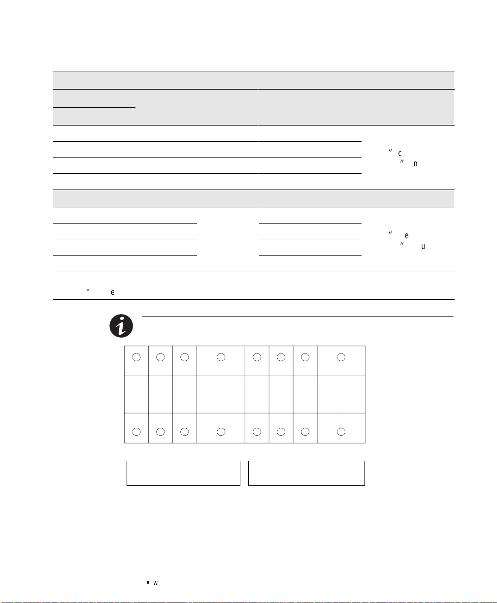
Computer and Alarm Connections
An interface for direct communication with your computer system is
supplied in the UPS.The interface consistsof two RS-232serial data
interfaces, fourisolated alarmcontacts,and remoteemergency
power-off (REPO).These interfaces are located beneath the control
panel (see Figure 18).
|
X2
REPO
9-Pin Port for RS-232 (Female) 9-Pin Port for RS-232 (Male)
15-Pin Relay Interface
®
Figure 18. REPO and Serial Port Locations
Hardware Installation
Figure 19 showsthe communication cablesconnected to the UPS.If you
have an optionalConnectUPS
bracket and reinstall with theadapter in position. Use the female 9-pin
UPSserial portfor the serial power connector. Followthe instructionsin
your ConnectUPS SL Operator’s Manual for configuration.
É
SL Adapter,remove the mounting
46
Powerware®9150 User’sGuide:www.powerware.com
Page 51

ConnectUPS
Mounting Bracket
Communication
Cables
Operation
Figure 19. Hardware Connections
RS-232 Serial Data Interfaces
The Powerware 9150 is designed to fully comply with LanSafe III/
FailSafe III Power Management Softwareand OnliNet
Management Software. If any other software is used, the pin
configuration should be verified.
The RS -232 interfaces use 9-pin,D-sub connectors.The information
includes data about the utility, the load, and the UPS.
NOTE The RS-232 interfacemustnot beconnectedto anyutility connectedcircuits.
Reinforced insulation to the utility is required.Thecommunicationsequipmentandthe
UPSshouldbeproperlygroundedbeforeconnectingordisconnecting a communication
cable.
Powerware®9150 User’sGuide:www.powerware.com
9
Strategic Power
47
Page 52

Operation
5432
1
879
6
Female Connector
(OnliNet orConnectUPS)
1234
786
Male Connector
(LanSafe III/FailSafe IIIor Modem)
5
9
Figure 20. 9-Pin Serial Port
Use the female connector for a computer running OnliNet software or
for a ConnectUPSAdapter. The communication settingsare 19200baud,
1 start bit, 8 data bits, No p arity, and 1 stop bit. See the followingtable
for pin assignments.
RS-232Connection (Female)
Pin 1 Receiveddata
Pin 2 Transmitted data
Pin 3 ACinput failure, closingto Pin 4
Pin 4 Signalground
Pin 5 Impendingbattery low, closing to Pin4
Pin 8 +DCauxiliarypower
Pin 9 Chassisground
Use the male connector for a computer running LanSafe III/FailSafe III
software or for a modem connection. The communication settings are 1
start bit, 8 da ta bits, N o parity, 1 stop bit, and XON/XOFF. The baud rate
is factory-set for1200 baud and can be changed with a menu invoked by
sending
Control-C to the UPS. See the followingtable for pin assignments.
48
RS-232Connection (Male)
Pin 1 Datacarrierdetected
Pin 2 Receiveddata
Pin 3 Transmitted data
Pin 4 Dataterminal ready
Pin 5 Signalground
Pin 7 Readytosend
Powerware®9150 User’sGuide:www.powerware.com
Page 53

Isolated Alarm Relay Interface
The isolated alarm relay interface uses a 15-pin, male, 42D-sub
connector.
12345678
9101112131415
Figure21. 15 -Pin SerialPort
Relay Interface of Powerware 9150
PinNo.Connection SystemState
Operation
Utility Failure 1-2Closed
1-3Closed
Low Battery 4-5Closed
4-6Closed
UPS on Bypass 10- 11 Closed
10- 12 Closed
UPSOnor
UPSAlarm
UPS Shutdown
(in Battery Modeonly)
7-9Closed
7-8Closed
13- 15 Closed UPS shutdown when operating in Battery Mode. UPS can be shutdown
NOTE The relay contactsare rated for a maximum1A/30 Vacor 0.2A/60Vdc.All
relayoutputs are isolatedfromthe othercircuitsofthe UPS.Therelay contacts must
notbe connectedto any utilityconnectedcircuits.Reinforcedinsulationtothe ut ilityis
required.
Line normal
Line failure
Battery normal
Battery low
OnUPS
On Bypass
UPSon
UPSalarm
by sending a hi-levelsignal (+5V to +15V) toPin 15(+) and 14(-), or by
connecting Pin 15 toPin 13. This signalmust be presentfor a minimum
of 5 seconds.
Powerware®9150 User’sGuide:www.powerware.com
49
Page 54

Operation
12-22AW
G
Remote Emergency Power-off Input
REPO is used to shut down the UPS from a distance. This feature can be
used for shutting down the load and the UPS by thermal relay, for
instance in the e vent of room overtemperature. Remote shutdown wires
areconnected onconnector X2 (see Figure 18 on page46).
The pins of connector X2 have been connected together. Whenthis
connection is open,the logiccircuitry completelyshutsdown the UPS,
thus preventing the power from supplying the load.
NOTE Inorder torestart the UPS,the pins ofconnectorX2 havetobe connected,the
batterybreaker (CB1) must bereset,and theUPS ON/OFFswitchmustbe turnedoff
and then backon.The pinsmustbe shortedinorder tokeep the UPSrunning.
Maximumresistance is10 ohm.
CAUTION
The REPO mustnotbe connectedtoany utilityconnected circuits.Reinforced
insulation to the utility isrequired. The REPOswitchmusthave a minimumratingof
24 Vdc and20 mA.
REPO Connections
WireFunction Terminal
REPO
L1 X2-1
L2 X2-2
Position
Terminal Wire Size
Rating
12- 22 AWG
(4- 0 mm2)
SuggestedWireSize
18 AWG (0.75 mm2)
When REPO is initiated, the UPS Alarm indicator blinks and the audible
alarmsounds 3 short beeps and 1 long beep.
Efficiency Optimizer Function
Thisfeaturecan be activatedby your service representative.The
Efficiency Optimizerfunctionminimizespower loss and reducespower
consumption by automatically switching betweenBypass andOnline
Mode according to the utility power condition.
When utility power is constant and free from disturbances, the UPS
switchesautomatically to BypassMode for maximum efficiency. The
UPSdetects all powerimperfectionsinstantly and returns to Online
Mode when necessary. As a result,the UPSreaches upto 98% average
efficiency.
50
Powerware®9150 User’sGuide:www.powerware.com
Page 55

CHAPTER 5
SPECIFICATIONS
Powerware 9150 Technical Specifications
RatedPower 8 kVA, 10kVA, 12.5 kVA at 0.7 power factor
Technology Online, double-conversion topologywith Static Bypass switch and 3-position
Maintenance Bypass switch.
Frequency independent operation.
InputVoltage Range 85- 146 Vacper phase
InputPowerFactor 0.95 typical
InputRatedVoltage 100/200, 110/220,120/240 Vac 180phase displacement
120/208, 127/220 Vac 120
InputFrequencyRange 45- 65 Hz
InputRatedFrequency 50/60 Hz selectable, auto-configuring
Nominal/Maximum Input 8kVA
OutputVoltage 100/200, 110/220, 120/240 Vac180phase displacement
120/208,127/220 Vac 120
50/60 Hz selectable, auto-configuring
OutputVoltage Regulation
5% dynamic at100% load change
Response time 1 ms
OutputVoltage Distortion < 2 % THD linear load
< 5 % THD non-linearload
OutputFrequency 50/60 Hz, selectableor auto-configuring
OutputFrequencyRegulation Synchronization to line,0.5,1.0 or2.0 Hz selectable
Free-running:
Slew rate 1.0, 2.0 or 3.0Hz/second selectable
OutputOvercurrent >112.5- 150% for 30seconds
>150% for 0.3seconds
phase displacement
10 kVA
12.5 kVA
phase displacement
2% static
0.005 Hz
Powerware®9150 User’sGuide:www.powerware.com
51
Page 56

Specifications
Powerware 9150 Model Specifications
Model12.5kVA
InputCurrent 54A 56A 52A 52A 49A
OutputVoltage 100/200V 110/220V 120/240V 120/208V 127/220V
OutputCurrent 52A 52A 52A 52A 52A
OutputkVA(line-lineloads) 10.4 11.4 12.5 10.8 11.4
OutputkVA(line-neutralloads) 10.4 11.4 12.5 12.5 13.2
OutputkW 7.28 8.75 8.75 8.75 8.75
OutputPeakCurrent 120A 120A 120A 120A 120A
Efficiency 89% 89% 89% 89% 89%
PowerDissipation (BTU/Hr) 3214 3690 3690 3690 3690
DC Voltage(48-Battery) 288V 288V 288V 288V 288V
Model10kVA
InputCurrent 45A 48A 43A 43A 41A
OutputVoltage 100/200V 110/220V 120/240V 120/208V 127/220V
OutputCurrent 41.7A 41.7A 41.7A 41.7A 41.7A
OutputkVA(line-lineloads) 8.3 9.2 10.0 8.7 9.2
OutputkVA(line-neutralloads) 8.3 9.2 10.0 10.0 10.6
OutputkW 5.8 7.0 7.0 7.0 7.0
OutputPeakCurrent 120A 120A 120A 120A 120A
Efficiency 89% 89% 89% 89% 89%
PowerDissipation (BTU/Hr) 2445 2950 2950 2950 2950
DC Voltage(32-Battery) 192V 192V 192V 192V 192V
DC Voltage(48-Battery) 288V 288V 288V 288V 288V
52
Powerware®9150 User’sGuide:www.powerware.com
Page 57

Specifications
Model8kVA
InputCurrent 39A 40A 36A 36A 35A
OutputVoltage 100/200V 110/220V 120/240V 120/208V 127/220V
OutputCurrent 33.3A 33.3A 33.3A 33.3A 33.3A
OutputkVA(line-lineloads) 6.7 7.3 8.0 6.9 7.3
OutputkVA(line-neutralloads) 6.7 7.3 8.0 8.0 8.5
OutputkW 4.7 5.6 5.6 5.6 5.6
OutputPeakCurrent 120A 120A 120A 120A 120A
Efficiency 88% 88% 88% 88% 88%
PowerDissipation (BTU/Hr) 2186 2728 2728 2728 2728
DC Voltage(32-Battery) 192V 192V 192V 192V 192V
DC Voltage(48-Battery) 288V 288V 288V 288V 288V
Physical Specifications
UPS Model8kVA Model 10kVA Model 12.5kVA
Width 15.752(400 mm) 15.752(400 mm) 15.752(400 mm)
Depth* 29.722(755 mm) 29.722(755 mm) 29.722(755 mm)
Height 28.232(717 mm) 28.232(717 mm) 28.232(717 mm)
Weightwith 48 InternalBatteries 550lb(250 kg) 550lb(250 kg) 550lb(250 kg)
Weightwith 32 InternalBatteries 457lb(208 kg) 457lb(208 kg) NA
*The optional Power Distribution Module adds 5.02(127 mm) tothe UPS depth.
Powerware®9150 User’sGuide:www.powerware.com
53
Page 58

Specifications
Environmental and Safety Specifications
AmbientTemperature 0Cto+40C operating
Ventilation Fan cooling, temperature uP monitored
Altitude 3,281 ft (1000 m) operating without derating
Humidity 5- 95% RH, noncondensing
AudibleNoise < 55 dBA at 1 meter distance
Safety UL 1778, cUL
EMC/RFI FCC class A
Surges ANSI/IEEE C62.41-1991
External Battery Cabinet Specifications
EBC-48 EBC-96
+15
C to +25C recommended
-10
C to +40C storage with batteries
C to +50C without batteries
-10
41,012 ft (12500 m) during transportation
54
DC-voltage 288V 288V
Batteries 48 x 7Ah 96x 7Ah
Weight 468 lb (213 kg) 765 lb (348kg)
Width 15.752(400 mm) 15.752(400 mm)
Depth 28.942(735 mm) 28.942(735 mm)
Height 28.462(723 mm) 28.462(723 mm)
Powerware®9150 User’sGuide:www.powerware.com
Page 59

CHAPTER 6
g
y
p
back
tot
heUPS
iti
TROUBLESHOOTING
The Powerware9150 is designed for durable,automatic operation and
also alerts youwhenever potential operating problems may occur.
Usually the alarms shown by the control panel do not mean that the
outputpower is affected. Instead,they arepreventive alarms intended to
alert the user. Use the following troubleshooting chart to determine the
UPS alarm condition.
Indicatoror Alarm Possible Cause Action
ON BATTERY
BYPASSED
2 short beeps
OVERLOAD LED is on.Power requirements exceed the
OVERTEMP
On or Blinking
LED is on. Autility failure has occurred and
the UPS isin Battery Mode. The alarm
sounds for five secondswhen battery
operation is initialized and then twice every
minute.
LED is blinking.The battery voltage islow
and has less thanfive minutes of backup
time left beforeUPS shutdown.
The UPS isin Bypass Mode. None. The alarm resets when the condition
UPS capacity (greater than 100%of nominal).
LED is blinking.Overload condition caused
the UPS toshut down (greaterthan 150% of
nominal for 0.3seconds).
One of themain UPS components is toohot
or the fan hasfailed.
7 short and 3longUPS beepsindicate the
temperature inside theUPS is more than 50
degrees.
4 short and 4long UPS beepsindicate a fan
failure.
None. The alarmresets when thecondition
becomes inactive.
Prepare your equipment for shutdown. When
utilityis restored, the UPS restarts automatically,
provides power totheload, and chargesthe
battery.
becomes inactive. Contact your service
representative if the conditionpersists.
Reduce the load.YourUPS continues to operate,
but may switch to Bypass Mode ifthe load
increases (112.5 - 150% of nominal for 30
seconds). The alarm resets when the condition
becomes inactive.
Reduce the loadand restart the UPS. You may
need to obtain alarger capacity UPS.
T urnthe MaintenanceBypass switch to the
SERVICE position. Clear vents. Remove any heat
sources. Allow the UPS tocool. If thealarm
disappears, turn the MaintenanceBypass switch
pos
on.Contactyour service
representative if the conditionpersists.
Powerware®9150 User’sGuide:www.powerware.com
55
Page 60

Troubleshooting
g
p
ActionPossible CauseIndicatoror Alarm
ALARM
On or Blinking
ALARMblinking
3 short beeps and1
long beep.
ALARM
On or Blinking
5 short beeps and4
long beeps.
ALARM
On or Blinking
11 short beeps and5
long beeps.
1 short and 4long beeps indicate aneutral
fault.
10 short and 5long beeps indicate aneutral
fault at startup.
7 short and 1long beep indicates aneutral
fault at shutdown.
REPO initiated. None. TheUPS remains off until theREPO switch
The circuit connected tothe REPO connector
is open and preventingUPS operation.
Battery failure. Batteryvoltage dropped too
fast and too lowafter charging.
Input phase error. Input phasesmust be rotated.Contact qualified
Silencing the Alarm
Press the RESET pushbutton on the LED panel to silence and reset the
alarm.
Input Neutral must be connected. Contact
qualified service personnel (such as a licensed
electrician).
is turned back on.
Check that theREPO connector isin place andthat
the circuit connected toit forms aclosed loop.
Contact your servicerepresentative if the
condition persists.
Verifythe battery circuit breaker(s)are turned on.
If the condition persists,the batteries may need
replacing. Contact yourservice representative.
service personnel (such asa licensed electrician).
56
Powerware®9150 User’sGuide:www.powerware.com
Page 61

Service and Support
If you have any questions or problems with yourUPS, call for service at
one of the following telephone numbers and ask for a UPS technical
representative:
Troubleshooting
Upgrading
In the United States
In Canada
All other countries
1-800-365-4892
1-800-461-9166
1-919-870-3149
Pleasehave the followinginformation ready whenyou call for service:
:
Model number
:
Serial number
:
Version number (if available)
:
Date of failureor problem
:
Symptoms of failure or problem
:
Customer returnaddressand contact information
The Powerware9150 features easy on-site upgrading. The following
tableshowstheavailableupgrades:
Unit/Batteries Available Upgrades
8 kVA, 32internal batteries 10kVA
8 kVA, 48internal batteries 10 kVA, 12.5kVA
10 kVA, 48internal batteries 12.5 kVA
To orderan upgrade or obtain more information contact yourlocal
PowerwareCorporation representative or call 1-800-365-4892 and ask
for MaintenanceContracts.
Powerware®9150 User’sGuide:www.powerware.com
57
Page 62

Troubleshooting
58
Powerware®9150 User’sGuide:www.powerware.com
Page 63

Powerware9150 Limited Warranty (US Only)
This limited warranty applies only to units installed in the fifty United States of America. Powerware
Corporation warrants theelectronics (Unit) to be free fromdefects in material and workmanship for a
period of two years from the Date of Delivery or 30 months from the Date of Manufacture, whichever
expiresfirst.
If, in Powerware Corporation’s opinion, the Unit fails to meet published specifications due to a defect in
material or workmanship covered by this warranty, Powerware Corporation will repair or replace the
warrantedUnitat no cost to the customer for replacement parts. Labor required to make the repairs or
replacement installation and travel costs incurred by Powerware Corporation’s representatives are not
includedunderthe terms of this limited warranty, except for labor required duringthe first 90 days after
the Date of Delivery. Equipment supplied by PowerwareCorporation, but not manufacturedby
Powerware Corporation, is warrantedsolelyby the manufacturer of such equipment.Powerware
Corporation does not warrant equipment not manufactured by Powerware Corporation (including, for
example, batteries).Equipment repaired or replaced pursuantto thiswarranty willbe warranted for the
unexpired portion of the original warranty subject to all the terms thereof.
This warrantydoes not apply to any Unitthathas been subjectto neglect, accident, abuse, misuse,
misapplication, incorrect connectionor that has been subject to repair or alteration not authorized in
writing by Powerware Corporation’s personnel. THIS WARRANTY IS THE PURCHASER’S (USER’S)
SOLE REMEDY AND IS EXPRESSLY IN LIEU OF ANY OTHER WARRANTY, AND THERE ARE NO
OTHER EXPRESSED OR IMPLIED GUARANTEES OR WARRANTIES (INCLUDING ANY IMPLIED
WA RRA NTY OF MERCHANTA BILITYOR FITNESS FOR PURPOSE). In no case will Powerware
Corporation’s liability under this contract exceed the value of the Unit furnished.
Powerware Corporation’s obligationundersaid warranty is conditioneduponreceipt of all payments due
(including interest charges, if any). During suchtime Powerware Corporation has notreceivedpayment
of any amount due inaccordance withthe contracttermsunderwhichthe equipmentis sold, Powerware
Corporation shall have no obligation under said warranty; also during this time, the period of said
warranty shall continue to run and the expiration of said warranty shall not be extended upon payment
of the overdue amount. These limitations to said warranty apply even in the event that the equipment is
sold by Powerware Corporation for resale to the ultimate user.
In no event shall Powerware Corporation be liable for any indirect, incidental, special or consequential
damages. Powerware Corporation shall not be responsible for failure to provide service or parts due to
causes beyond Powerware Corporation’s reasonable control. THIS LIMITED WARRANTY APPLIES
ONLY TO THE ORIGINAL PURCHASER OF THE UNIT, IS VOID, AND POWERWARE CORPORATION
DISCLAIMS ALLWARRANTY OBLIGATIONSWHATSOEVER,EXPRESSED OR IMPLIED, UNLESS
USER RETURNS TO POWERWARE CORPORATION THE INCLUDED WARRANTY VALIDATION
CARD WITHIN THIRTY (30) DAYS OF DELIVERY.
Costs for replacementequipment installation, material freight charges, travel expenses and labor of
Powerware Corporation’s representatives will be borne by the User. Any advice furnished the User before
or after delivery in regard to use or application of PowerwareCorporation equipment is furnished
without charges and on the basis that it represents Powerware Corporation’s best judgement under the
circumstances. The use of any suchadvice by the User is solely and entirely at his or herown risk.
Page 64

60
6
0
`
`
Powerware®9150 User’sGuide:www.powerware.com
 Loading...