

Page 1
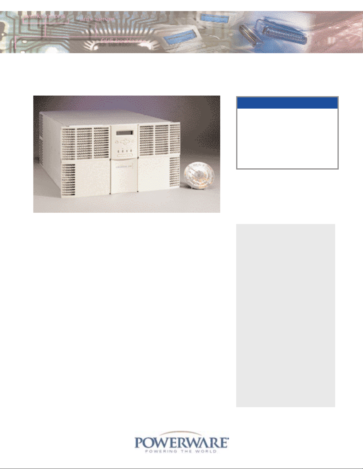
Powerware®5140 Rack-Mount UPS
Features
A Power Factor Corrected (PFC) design
protects more equipment
A 6U rack height conserves valuable
rack space
A Advanced Battery Management
(ABM™) doubles battery service life
A Buck and Boost voltage
regulation with pure sine
wave output
A Extended Battery Modules (EBMs)
prolong run times
A Modular design eases setup and
service
A Load Segments (separate receptacle
groups) enable scheduled shutdowns
and maximize run time for
critical devices
A Hot-Swappable batteries and Manual
Bypass Switch simplify service
A Backed by 10-Year Pro-rated
Warranty (U.S. and Canada)
In addition to its exceptional power rating
and size, the Powerware 5140 also
incorporates Advanced Battery
Management (ABM™) which assures
reliability and improves performance by
doubling battery service life, optimizing
recharge time, and providing up to a 60day notice of the end of useful battery life.
The Powerware 5140 utilizes multiple
receptacle groups, called Load Segments,
which can be pre-configured to shutdown
peripherals first to effectively triple battery
run times for the most critical equipment.
Extended Battery Modules (EBMs) are also
available to extend run times, and to
preserve data integrity, the Powerware
5140 is bundled with award-winning
LanSafe III and FailSafe III power
management software.
T
o meet the power protection needs of
rapidly expanding rack-based
applications, Powerware Corporation
(formerly Exide Electronics) proudly introduces the Powerware 5140 Rack-Mount
uninterruptible power system (UPS). The
Powerware 5140 is powerful and flexible
enough to respond to the demands of
virtually any Enterprise computing
network.
The Powerware 5140 is designed with a
unity power factor rating, meaning it is
ideally suited to meet the requirements of
today's Power Factor Corrected (PFC)
loads. With proven and reliable technology,
it delivers up to a third more power than
traditionally rated UPSs while still
occupying only 6U (10.5 inches) of
valuable rack space.
Rating: 6000 VA/
6000 Watts
Voltage: 200-240 Vac
Frequency: 50/60 Hz
Configuration: 6U rack-mount
for standard
19-inch racks
Product Snapshot
Page 2
Technical Specifications
1
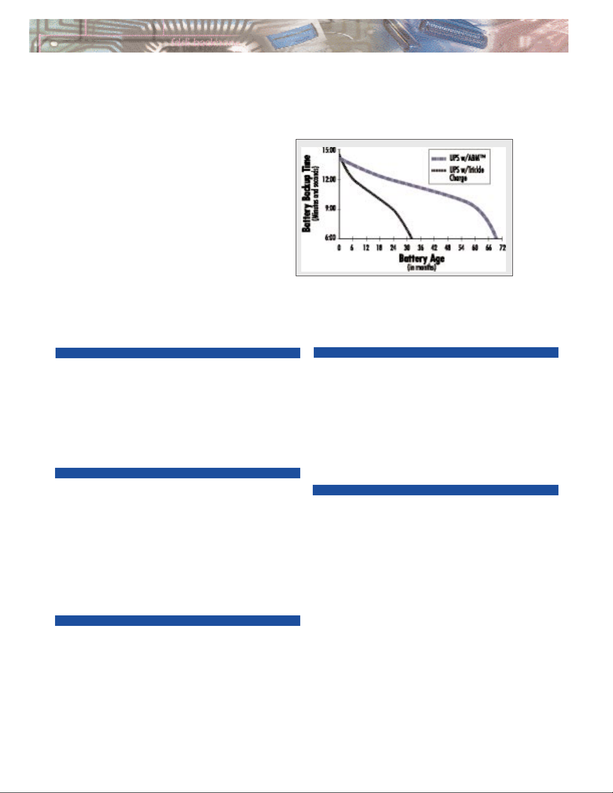
The lead-acid batteries typically used in a
UPS are considered viable as long as they
can maintain backup times of at least half
that of new batteries. The illustration to the
right shows that batteries that are constantly
trickle charged (as are virtually all other UPS
batteries on the market today) reach the end
of their useful life in less than half the time
of batteries charged using ABM. ABM uses a
patented three-stage charging technique that
not only doubles battery service life, but
also optimizes battery recharge time and
provides up to a 60-day advanced notification of pending end of useful battery life.
Advanced Battery Management (ABM™) Technology Doubles Battery Service Life
Data based upon tests performed by an independent battery manufacturer.
ELECTRICAL INPUT
Voltage 200, 208, 220, 230, & 240 Vac user-selectable;
see Model Selection Guide for default settings
Normal Voltage ±20% of nominal voltage without using batteries
Range
Extended Voltage 160-288V without using batteries (set via front panel)
Range
Frequency 50/60 Hz, ±3 Hz (+5/-3 Hz with extended voltage range)
Connection Hardwired
Efficiency 96%
ELECTRICAL OUTPUT
Power Out 6000 VA/6000 Watts
Voltage Range ±10% of nominal voltage
(online)
Voltage Range ±5% of nominal voltage
(on battery)
Wave Form Sine Wave
(on battery)
Frequency Same as input (±0.5% during battery operation)
Connections Receptacles or hardwired; see Model Selection Guide
Max Current 29A at 208 Vac; 26A at 230 Vac
Output Protection Resettable circuit breakers
BATTERY
Type Maintenance-free, sealed, valve-regulated lead-acid
(VRLA), (28), 12V 5 AH
Extended Batteries Maximum of 2 Extended Battery Modules (EBMs)
Backup Time See Battery Run Times table
Recharge Time <3 hours to 80% usable capacity
Extended Battery <10 hours to 80% usable capacity
Recharge Time
COMMUNICATIONS
Serial Ports (2) Serial communication ports for use with power
management software and installable option cards,
including ConnectUPS SLC-EM SNMP Adapter and the
Port Expander Card
User LEDs Normal Operation (green), On Battery (yellow),
On Bypass (yellow), and Alarm (red)
LCD Two-line LCD with three button control
LCD Languages Danish, Dutch, English, French, German, Spanish,
Italian, and Japanese
Front Panel Buttons On, Off, and Alarm Silence/Self Test
Communications 6-foot communication cable included
Cable
ENVIRONMENTAL AND SAFETY
Operating 10°C to 40°C (25°C for optimal performance)
Temperature
Transit Temperature -20°C to 55°C
Storage Temperature 0°C to 25°C
Humidity (Operation) 20 to 80% (noncondensing)
Humidity 5 to 95%
(Non-operating)
Operating Altitude 0 to 10,000 feet (non-operating: 0 to 30,000 feet)
Audible Noise 55 dBA at 1 meter
Safety Markings UL, CSA, NOM. Models PW5140 6000i and
PW5140 6000 HW also CE and VDE
Safety UL1778; CSA22.2 No.107.1,No.107.2,No.950; CB
Certifications Bulletin No.86AI; EN50091-1; EN60950;
EMKO-TSE207/95; NOM-019-SCFI-1993
EMC Markings FCC-A; CISPR-A; VCCI
Immunity IEC 801-2, IEC 801-3, IEC 801-4, IEC 801-5
Surge Suppression Conforms to IEEE 587B and ANSI C62.41
REPO Port Meets NEC code 645-11 intent and UL requirements
1. Due to continuing product improvement programs, specifications are subject to
change without notice.
Page 3

Unity Power
Factor Rating
What does unity power factor rating mean?
Quite simply, it means that the watt rating of the
UPS is equal to its VA rating. Traditionally,
UPSs have been designed, built, and sold with a
power factor rating of approximately 0.6 to 0.7.
For example, a 1000 VA UPS could supply a
maximum of 600 to 700 watts. Historically, this
0.7 power factor was appropriate for the
majority of computer loads the UPS was
intended to support since most computers
demanded power at a 0.7 power factor.
Today, however, a large percentage of high-end
computers, utilize Power Factor Corrected
(PFC) power supplies, which have a power
factor of approximately 1.0. Take a look at the
configuration below:
To support this load, you need to select a
UPS with a rating that meets or exceeds both
the watt and VA demand shown above.
A traditionally rated 5000 VA/3750 watt UPS
without a unity power factor rating cannot be
used. The Powerware 5140, on the other
hand, has capacity to spare.
Powerware 5140 Features
Load Segments
Load Segments are groups of receptacles that can be independently controlled via the front
panel LCD interface and/or LanSafe III/FailSafe III, which is bundled with the Powerware
5140. Load Segments provide extended battery run times and flexible management of the
UPS. The five Load Segments of model PW5140 6000i are outlined below.
Front Panel Display
Extended Battery Modules (EBMs)
To extend battery backup times, you can connect up to two EBMs. Each EBM occupies
3U (5.25 inches) of rack space.
Load Segments divide the
Powerware 5140 into five
virtual UPSs
Shut down Load Segments
to decrease load and
extend backup time for
other Load Segments
Reboot a locked up server
by turning a Load Segment
off and on
LCD Status Screen
Menu Navigation
Keys
Bypass LED
Alarm LED
UPS On Battery
Power On (Normal)
On
Off
Alarm Silence/
Self-Test
You can hot-swap both the
standard batteries and EBMs
without powering down the
connected load. This makes it
possible to extend the life of
the UPS without returning the
unit for service.
Load: Load:
Equipment Watts VA
(3) Servers* 3300 3366
(2) Workstations* 1000 1020
(1) Color Monitor 200 300
Total 4500 4686
*Equipment with PFC power supplies.
Page 4

Powerware®5140 Model Selection Guide
BATTERY RUN TIMES
STANDARD ONE ADDITIONAL TWO ADDITIONAL
LOAD BATTERIES EXTENDED BATTERY MODULE EXTENDED BATTERY MODULES
1000 Watts 1 hour 2 minutes 2 hours 24 minutes 3 hours 56 minutes
2000 Watts 28 minutes 1 hour 6 minutes 1 hour 47 minutes
3000 Watts 18 minutes 40 minutes 1 hour 6 minutes
4000 Watts 12 minutes 28 minutes 47 minutes
5000 Watts 8 minutes 21 minutes 36 minutes
6000 Watts 6 minutes 18 minutes 28 minutes
This table provides typical information. Battery times are approximate and may vary with equipment, configuration, disk access, battery use, temperature, etc.
REAR PANELS
PW5140 6000i
PW5140 6000
MODEL POWER OUT INPUT/OUTPUT FREQUENCY INPUT OUTPUT DIMENSIONS WEIGHT
NUMBER (VA/WATT)VOLTAGE (VAC)(HZ)CONNECTION RECEPTACLES (HXWX D)
1
(KG/LB)
(12) IEC-320, C13 & 10.5 x 17.25 x 24.3 in
PW5140 6000i 6000/6000 208/230
2
50/60
3
Hardwired (3) IEC-320, C19
4
26.7 x 43.8 x 61.7 cm 136/300
6
(2) L6-30R & 10.5 x 17.25 x 24.3 in
PW5140 6000 6000/6000 208/230
2
50/60
3
Hardwired (2) IEC-320
5
26.7 x 43.8 x 61.7 cm 136/300
6
Hardwired & 10.5 x 17.25 x 24.3 in
PW5140 6000 HW 6000/6000 208/230
2
50/60
3
Hardwired (2) IEC-320
5
26.7 x 43.8 x 61.7 cm 136/300
6
Options
Custom 5.25 x 17.25 x 22.5 in
PW5140 BATT – – – Adapter – 13.3 x 43.8 x 57.2 cm 81.6/180
Custom 1.98 x 19.28 x 9.90 in
PW5140 PDU
7
250/250 120 60 Adapter (2) 5-15R 5.03 x 48.97 x 25.15 cm 8.6/19
Adjustable; fits
PW5119 MK23 –––– –standard 19-inch rack 4.5/10
1. 19-inch wide front panel with a 17.25-inch wide chassis; depth does not include front panel (.5 inches) 2. 208/230 Vac auto-sensing default. User-selectable via
LCD interface for 200, 208, 220, 230, and 240 Vac. 3. Automatic frequency synchronization. 4. Divided into 5 Load Segments. 5. Divided into 2 Load Segments;
IEC-320 receptacles are used to connect optional PW5140 PDU. 6. Shipping weight is 325 pounds (147 kg). 7. Sidewall design occupies 0U of rack space.
PW5140 6000 HW
China and North Asia
Hong Kong: 852.2745.6682
Australia and South Pacific
Sydney, Australia: 61.2.9878.5000
Canada
Toronto, Ontario: 416.798.0112
Powerware Corporation
Corporate Headquarters
8609 Six Forks Road
Raleigh, NC 27615 U.S.A.
Toll Free: 1.877.797.9273 (PWRWARE)
or 919.872.3020
Fax: 1.800.753.9433
or 919.870.3411
E-mail: info@powerware.com
www.powerware.com
Latin America/Caribbean
Sunrise, FL: 954.835.1180
Europe/Middle East/Africa
Berkshire, England: 44.1753.606700
Southeast Asia
Singapore: 65.861.9877
A (2) INSTALLABLE OPTION SLOTS
B (2) COMMUNICATION PORTS
CMANUAL BYPASS SWITCH
D REPO PORT
EHARDWIRE INPUT
FLOAD SEGMENT 1
GLOAD SEGMENT 2
HLOAD SEGMENT 3
ILOAD SEGMENT 4
JLOAD SEGMENT 5
KCIRCUIT BREAKER(S )
L IEC-320 RECEPTACLES FOR PDU CONNECTION
MHARDWIRE OUTPUT
Revision 5140FXA 7/99
Reprint 7/99
 Loading...