

Page 1

02/20/2001
Powerware®5140
User’s Guide
6000VA/6000W
www.powerware.com
Page 2

Requesting a DeclarationofConformity
The EC Declaration of Conformityisavailable upon request for productswith a CE mark. For copies of the EC
Declaration of Conformity, contact:
Powerware Corporation
Koskelontie 13
FIN-02920 Espoo
Finland
Phone: +358-9-452661
Fax: +358-9-452-66395
EMC Statement
Some configurations are classified under EN50091-2 as “Class-A UPS for Unrestricted Sales Distribution.” For these
configurations, the following applies:
WARNING Thisisa Class-A UPS Product. In a domestic environment, this productmaycause radio interference, in
which case, the user may berequired to takeadditional measures.
Powerware and ConnectUPSare registeredtrademarks and Advanced Battery Management (ABM)isatrademark of
Powerware Corporation.
.
Copyright 1999 Powerware Corporation, Raleigh, NC. All rights reserved. No part of this document may be reproduced
in any way without the expresswritten approvalof Powerware Corporation.
Page 3

FCC Statement
The UPSconfigurationsvary. Some configurations may ormaynot be classified by the FederalCommunications
Commission (FCC). If your unit is classified by these standards, the corresponding information applies:
Class A
NOTE Thisequipment has been testedand found to comply withthe limits for a Class Adigital device, pursuantto Part
15 of the FCC Rules. These limits are designed to provide reasonable protection against harmful interference when the
equipment is operated in a commercial environment. This equipment generates, uses, and can radiate radio frequency
energyand, if not installedandused in accordance withthe instruction manual, may cause interference to radio
communications. Operationof this equipmentin a residentialarea is likely to cause interference in whichcase the user will
be required to correctthe interference at his own expense.
Page 4
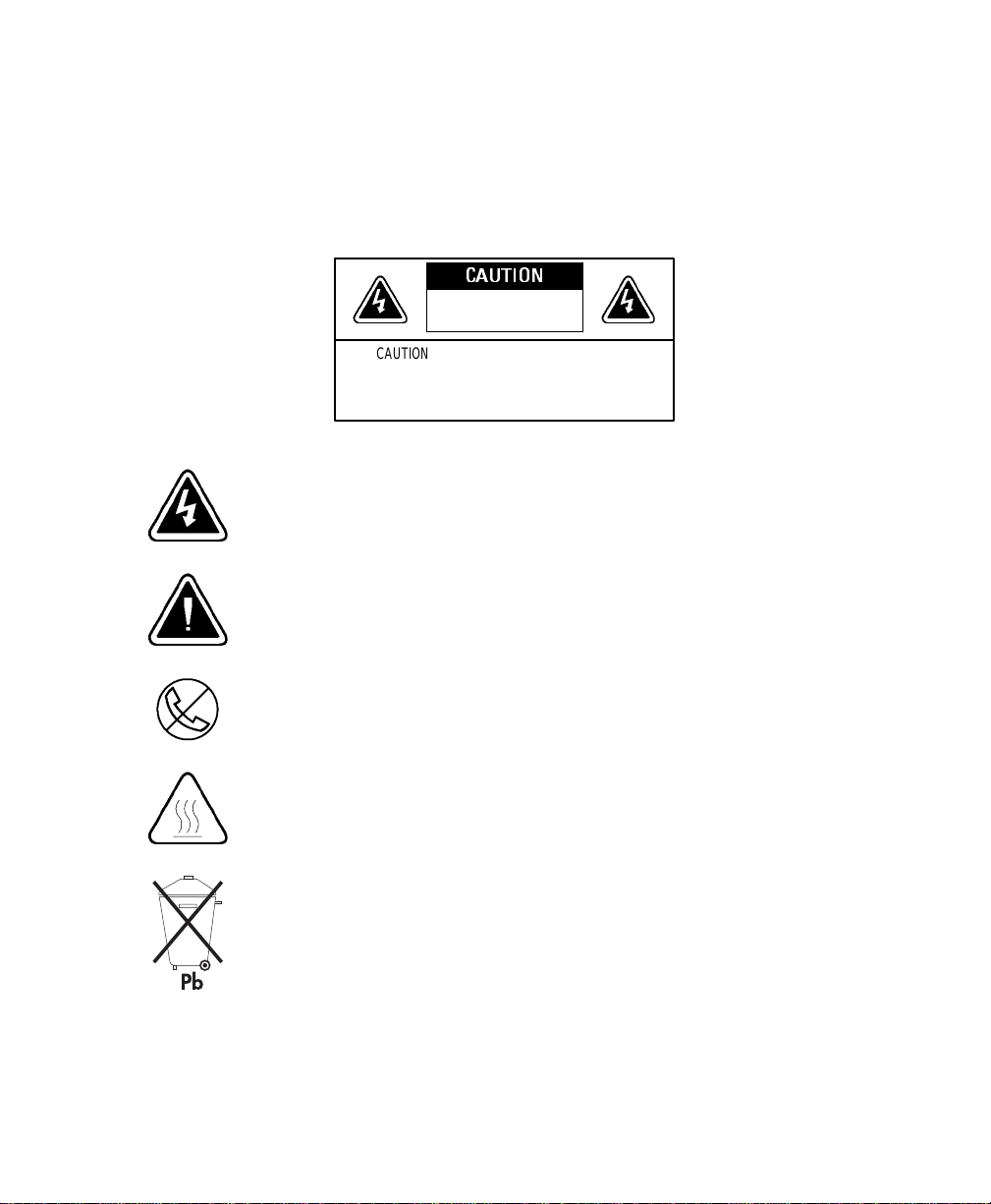
Special Symbols
The following are examples of symbols used on the UPS to alert you to importantinformation:
CAUTION
Riskof ElectricShock
DoNot OpenCover
CAUTION Toreduce therisk ofelectricshock,
Donotremove cover (orback)
Nouser-serviceableparts inside
Refer servicing to the factory
RISKOFELECTRIC SHOCK - Indicates that a risk of electric shock is present and
the associated warning should be observed.
CAUTION: REFER TO OPERATOR’SMANUAL - Refer to your operator’s manual for
additional information,suchas important operating and maintenance
instructions.
RJ-45RECEPTACLE- This receptacle provides network interface connections.
Do not plug telephone or telecommunications equipment into this
receptacle.
HEATPRESENT - Indicates the presence of a hot surface or hot component.
Do not touch; allow the surface to cool before touching.
This symbol indicates that you should not discard the UPS or the UPS
batteries in the trash.The UPS may contain sealed, lead-acid batteries.
Batteriesmustbe recycled.
Page 5

TABLE OF CONTENTS
1 Powerware 5140 –Oneof the Best! 1..................................
2 Safety Warnings 3.................................................
Sikkerhedsanvisninger 5.........................................................
Belangrijke Veiligheidsinstructies 6..................................................
Tärkeitäturvaohjeita 7..........................................................
ConsignesdeSécurité 8.........................................................
WichtigeSicherheitsanweisungen 9.................................................
Importantiistruzioni di sicurezza 10..................................................
Viktig Sikkerhetsinformasion 11.....................................................
RegulamentosdeSegurança 12.....................................................
Requisitosde seguridad 13........................................................
Viktig säkerhetsinformation 14......................................................
3 Installation 15.....................................................
InspectingtheEquipment 15.......................................................
UnpackingtheUPS 15............................................................
Installation Overview 16..........................................................
Installing the Chassis 17..........................................................
Installing the Batteries 18.........................................................
ElectricalInstallation 22..........................................................
Installing Optional Equipment 25....................................................
RemoteEmergencyPower-Off 25.................................................
OptionModules 26............................................................
PowerDistribution Unit 26......................................................
UPSStartup 27.................................................................
4 Operation 31......................................................
OperatingModes 31.............................................................
NormalMode 32.............................................................
BatteryMode 32.............................................................
StandbyMode 32.............................................................
UPSShutdown 32...............................................................
StartingtheUPSonBattery 33......................................................
MaintenanceBypass 33..........................................................
Powerware®5140 User’s Guide:www.powerware.com
i
Page 6

Table of Contents
5 Front Panel Menus 35...............................................
ControlButtons 35..............................................................
EscapeButton 35.............................................................
UporDownArrowButtons 36....................................................
LeftorRightArrowButtons 36...................................................
Select Button 36.............................................................
MainMenu 36.................................................................
Status 37...................................................................
Meters 37..................................................................
Active Alarms 37.............................................................
BatteryData 38..............................................................
FirmwareVersion 38...........................................................
LoadControl 38..............................................................
Display Test 39...............................................................
System Setup 39................................................................
SetHW(Hardware)Configuration 40...............................................
SetLanguage 40.............................................................
SetAlarmHorn 40............................................................
SetPassword 40.............................................................
SetSyncRange 40............................................................
Comm(Communications)Setup 41.................................................
SetVoltage 42...............................................................
SetSiteFault 42.............................................................
SetSleepMode 42...........................................................
6 Configuration 43...................................................
LoadSegments 43..............................................................
Communication Port Configuration 44.................................................
NominalInputVoltage 46.........................................................
7 Battery Maintenance 47.............................................
UPSandBatteryCare 47..........................................................
StoringtheUPSandBatteries 47..................................................
Whento ReplaceBatteries 47......................................................
ReplacingBatteries 48...........................................................
Hot-SwappingtheBatteries 49...................................................
ReplacingtheBatteriesWithout Utility Power 51......................................
Testing New Batteries 52.........................................................
Recycling the Used Batteries 52.....................................................
ii
Powerware®5140 User’s Guide:www.powerware.com
Page 7

Table of Contents
8 Specifications 53..................................................
9 Troubleshooting 57.................................................
InitiatingtheSelf-Test 57.........................................................
SiteWiringFault 57.............................................................
AudibleAlarms and UPS Conditions 58................................................
Silencing an AudibleAlarm 58....................................................
ServiceandSupport 60...........................................................
Powerware®5140 User’s Guide:www.powerware.com
iii
Page 8

Table of Contents
iv
Powerware®5140 User’s Guide:www.powerware.com
Page 9
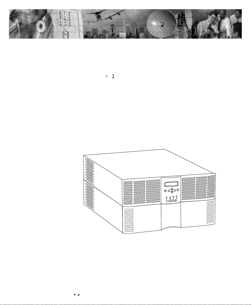
CHAPTER 1
POWERWARE 5140 – ONE OF THE BEST!
The Powerware95140 uninterruptiblepower system (UPS) protects
your sensitive electronic equipment from basic power problems such as
power failures, power sags, power surges, brownouts, and line noise.
Poweroutagescan occur when you least expect it and power quality
can be erratic.Thesepower problemshavethe potential to corrupt
criticaldata,destroyunsaved work sessions,anddamage hardware —
causing hoursof lost productivity and expensive repairs.
Withthe Powerware 5140, you can safely eliminate the effects of power
disturbances and guardthe integrity of your equipment.The Powerware
5140 is flexible and powerful enough to handle e xpa nding rack-based
applications.
Becausean integralpart of power protection is power management
software,the Powerware 5140 comes fully equipped with two
communication ports, two serialcables,anda CD containing both
LanSafeIII for networked systems and FailSafe III for standalone
systems.
Powerware®5140 User’s Guide:www.powerware.com
Figure1.ThePowerware 5140
1
Page 10

Powerware5140–One of the Best!
Providing outstanding performance and reliability, the Powerware
5140’s unique benefits include the following:
:
Power-factor corrected (PFC)designallowsyouto protect more
equipment by usinga unity power rating of 6000 VA/6000W.
:
6U rack height conservesvaluable rack space.
:
Easy UPS configurationand monitoring through the LCD front panel.
:
Advanced Battery Management (ABMZ) doubles battery service life,
optimizesrecharge time, and provides a warning up to 60 days before
the end of useful battery life.
:
Extended runtimes with Extended Battery Modules (EBM).
:
Hot-swappable batteries simplify maintenance by allowing you to
replacebatteriessafelywithout poweringdownthe criticalload.
:
Start-on-battery compatibilityallowsyouto power up the UPS even
if utility power is not available.
:
Sequential shutdown and load management through segmented
outputreceptacles.
:
Emergency shutdown control through the Remote Emergency
Power-Off (REPO) port.
:
Maintenance Bypass mode allows you to switch the UPS to utility
power for easy maintenance or upgrades.
:
Option modules provide enhanced communication capabilities for
increased power protectionandlongerbatterybackup times.
:
Compatibility with the Powerware ConnectUPS
flexible network control.
:
The Powerware 5140 is backed by worldwide agency approvals.
9
Adapter provides
2
Powerware®5140 User’s Guide:www.powerware.com
Page 11

CHAPTER 2
SAFETY WARNINGS
IMPORTANT SAFETY INSTRUCTIONS
SAVE THESE INSTRUCTIONS.This manual containsimportantinstructions that you
shouldfollowduring installationandmaintenanceoftheUPSandbatteries.Please
read allinstructions before operating the equipment and save thismanualforfuture
reference.
ThisUPScontains LETHAL VOLTAGES.Allrepairs and serviceshouldbeperformed
byAUTHORIZED SERVICE PERSONNEL ONLY.Thereare NO USER
SERVICEABLE PARTS insidetheUPS.
Onlyqualified servicepersonnel(such as a licensedelectrician) should perform the
UPSandoptionmodulesinstallation and initialstartup.Risk of electricalshock.
The only user operations permitted are:
:
Starting up and shutting down the UPS
:
Operatingtheuserinterface
:
Connecting data interfacecables
:
Monitoring the UPS withpower managementsoftware
DANGER
WARNING
Powerware®5140 User’s Guide:www.powerware.com
3
Page 12

Safety Warnings
CAUTION
:
Inputovercurrentprotectionanddisconnect switchmustbeprovided by others.
:
To reduce the risk of fire, connectonlytoacircuit provided with40 amperes
maximumbranchcircuit overcurrentprotectioninaccordance with the National
ElectricalCode, ANSI/NFPA 70 and Canadian ElectricalCode,C22.1.
:
Batteriescanpresentarisk of electricalshockorburnfromhighshortcircuit
current.Observe proper precautions.Servicingshouldbeperformedbyqualified
servicepersonnel knowledgeableofbatteriesandrequiredprecautions. Keep
unauthorizedpersonnelawayfrombatteries.
:
Proper disposalofbatteriesis required. Refer to your localcodesfordisposal
requirements.
:
ThisUPScontainsitsown energy source(batteries). The UPSoutputmaycarrylive
voltageevenwhentheUPSisnot connected to an AC supply.
:
Neverdispose of batteriesina fire.Batteriesmayexplodewhen exposedtoflame.
:
To reduce the risk of fire or electricshock, installthisUPSin a temperatureand
humiditycontrolled,indoorenvironment,freeofconductivecontaminants.Ambient
temperaturemustnotexceed40C(104F).Donotoperatenearwateror
excessive humidity (95% max).
4
Powerware®5140 User’s Guide:www.powerware.com
Page 13

Sikkerhedsanvisninger
DenneUPS(ubrudtstrømforsyning) indeholderLIVSFARLIGSPÆNDING. Alreparation
og servicebørKUN foretagesafAUTORISERET SERVICEPERSONALE. Der er INGEN
DELEiUPS’en, hvorpå en BRUGERBØRFORETAGESERVICE.
:
Batterierkangiverisiko tilelektriskstød eller forbrændingfra stærk
kortslutningsstrøm. Observerkorrekteforholdsregler.
:
Korrektafkastningafbatterier kræves. Henvend Demtildereslokale love m.h.t.
affaldsreguleringer.
:
DenneUPSindeholderenselvforsynende energikilde(batterier).
Udgangskontakternekan overføre stromførende spænding,nårUPS’enikke er
forbundet med en vekselstrømsforsyning.
:
Brændaldrigbatterierne.Batteriernekaneksplodere,nårdeudsættesforflammer.
:
InstallerUPS’en i et temperatur-ogfugtighedskontrolleret miljø frit for
konduktiverendemateriale for,atreducererisikoen for brand og elektriskstød.
Omgivelsestemperaturenmåikkeoverskride40C.Betjen ikkeudstyrer inærheden
af vandellerurimelig fugtighed (95% maksimum).
Safety Warnings
FARE
ADVARSEL
Powerware®5140 User’s Guide:www.powerware.com
5
Page 14

Safety Warnings
Belangrijke Veiligheidsinstructies
DezeUPSbevatLEVENSGEVAARLIJKE ELEKTRISCHESPANNING.Alle reparaties en
onderhoud dienenUITSLUITEND DOOR ERKEND SERVICEPERSONEELteworden
uitgevoerd.Erbevinden zichGEENONDERDELEN inde UPSdieDOORDE GEBRUIKER
kunnenwordenGEREPAREERD.
:
Batterijenkunnengevaarvoor elektrische schokof brandwonden veroorzakenals
gevolgvanhogekortsluitstroom.Volg dedesbetreffendeaanwijzingen op.
:
Debatterijenmoetenopdejuistewijzewordenopgeruimd.Raadpleeg hiervooruw
plaatselijke voorschriften.
:
DezeUPSbevatzijneigenenergiebron (batterijen).Deuitvoercontactdozenkunnen
onder spanningstaanwanneerdeUPSnietopeenwisselstroomvoedingis
aangesloten.
:
Nooitbatterijeninhetvuurgooien.De batterijen kunnen ontploffen.
:
Teneinde de kans op brand of elektrischeschokteverminderendient deze UPS in
een gebouw met temperatuur-envochtigheidregelingte worden geïnstalleerd,
waargeengeleidendeverontreinigingen aanwezigzijn.Deomgevingstemperatuur
mag40Cnietoverschrijden.Nietgebruikenindebuurtvanwaterofbij zeer hoge
vochtigheid(max. 95%).
GEVAAR
OPGELET
6
Powerware®5140 User’s Guide:www.powerware.com
Page 15

Tärkeitä turvaohjeita
Tämä UPSsisältää HENGENVAARALLISIAJÄNNITTEITÄ. Kaikkikorjaukset ja huollot
on jätettäväVAIN VALTUUTETUNHUOLTOHENKILÖSTÖN TOIMEKSI. Tämä UPS ei
sisällä MITÄÄN KÄYTTÄJÄNHUOLLETTAVIAOSIA.
:
Akustosaattaaaiheuttaasähköiskunvaarantaisyttyä tuleenmikäli akusto
kytketäänoikosulkuun.Noudataasianmukaisia ohjeita.
:
Akustotäytyy hävittää säädöstenmukaisella tavalla.Noudatapaikallisia
määräyksiä.
:
TämäUPSsisältää oman energialähteen (akuston).Ulostulorasioissavoi olla
jännite,kunUPSei ole liitettynä verkkojännitteeseen.
:
Äläkoskaan heitä akkuja tuleen.Nevoivaträjähtää.
:
VähentääksesitulipalonjasähköiskunvaaraaasennatämäUPS sisätiloihin, joissa
lämpötilajakosteus on säädettävissäjajoissa ei ole sähköäjohtavia
epäpuhtauksia.Ympäristön lämpötilaeisaaylittää 40C.Äläkäytä lähellä vettä
tai liian kosteissa oloissa (95 % maksimi).
Safety Warnings
VAARA
VARO
Powerware®5140 User’s Guide:www.powerware.com
7
Page 16

Safety Warnings
Consignes de Sécurité
Consignes Importantes De Sécurité - Conserver Ces Instructions
Cette Notice Contient Des Consignes Importantes De Sécurité
CetUPScontientdestensions mortelles.Toute opération d’entretienet de réparation
doit être effectuée UNIQUEMENT PAR UN PERSONNEL QUALIFIÉ AGRÉE. L’UPS n’a
AUCUNEPIÈCE RÉPARABLEPARL’UTILISATEUR.
:
Unebatteriepeutprésenterunrisquedechocélectrique ou de brûlure par un
transfertd’énergieouuncourt-circuit. Prendre lesprécautionsnécessaires.
:
Unemiseaurebutréglementaire desbatteriesestobligatoire. Consulterles
règlementsen vigueurdans votrelocalitéconcernantlamiseaurebut debatteries.
:
CetUPScontientsapropresource d’énergie (batteries).Lesprises de sortie
peuventêtresoustensionmême lorsquel’UPS n’est pas branchésurlesecteur.
:
Ne jamaissedébarrasser de batteries en les incinérant.Elles risquent d’exploser
lorsqu’elles sont exposéesàuneflamme.
:
Afinderéduirelesrisques d’incendieetdechocélectrique, installerl’UPS
uniquementdans unespaceintérieuràtempérature ethumiditécontrôléesetsans
matérielconducteur.Latempératureambiantenedoitpasdépasser 40C.Nepas
utiliser à proximité d’eau ou dansuneatmosphèreexcessivementhumide
(95 % max).
DANGER!
ATTENTION!
8
Powerware®5140 User’s Guide:www.powerware.com
Page 17

Wichtige Sicherheitsanweisungen
Lebensgefahr!Diese USV enthält TÖDLICHE SPANNUNGEN!Alle Reparatur-und
Wartungsarbeitensollten NUR VONAUTORISIERTEM WARTUNGSPERSONAL
durchgeführtwerden.Indieser USVbefindensich KEINE VOM BENUTZERZU
WARTENDEN TEILE.
:
BatterienkönnenaufgrundvonKurzschlußhochstromElektroschocks oder
Verbrennungenverursachen. EntsprechendeAnleitungenbefolgen.
:
DieBatterienmüssen ordnungsgemäß weggeworfen werden.
Entsorgungsanweisungen sind den örtlichen Vorschriften zu entnehmen.
:
DieseUSVenthält ihre eigene Stromquelle(Batterien).An den
Ausgangssteckdosen kann Spannung anliegen,selbst wenn die USV nichtaneine
Wechselspannungsquelleangeschlossen ist.
:
Batterienniemalsverbrennen, da sie explodierenkönnen.
:
UmdieBrand- oder Elektroschockgefahr zuverringern,diese USVnurinGebäuden
mit kontrollierter Temperatur und Luftfeuchtigkeit installieren, in denen keine
leitendenSchmutzstoffen vorhanden sind.DieUmgebungstemperatur darf 40C
nichtübersteigen.Die USV nichtinderNähevonWasser oder in extrem hoher
Luftfeuchtigkeit (max. 95 %) betreiben.
Safety Warnings
WARNUNG
VORSICHT!
Powerware®5140 User’s Guide:www.powerware.com
9
Page 18

Safety Warnings
Importanti istruzioni di sicurezza
LaTENSIONEcontenutainquesto gruppo staticodicontinuità è LETALE.Tuttele
operazionidiriparazione e di manutenzione devono essereeffettuate
ESCLUSIVAMENTE DA PERSONALE TECNICO AUTORIZZA TO.All’interno del gruppo
staticodicontinuità NON visonoPARTI RIPARABILI DALL’UTENTE.
:
Lebatteriepossono presentare rischiodiscossaelettricao di ustioniprovocateda
altacorrentedovutaacortocircuito. Osservareleappositeistruzioni.
:
Lebatteriedevonoesseresmaltite in modo corretto.Per irequisitidismaltimento
fare riferimentoalledisposizionilocali.
:
Questogruppostaticodicontinuità contieneuna fonte di energiaautonoma(le
batterie).Lepresediuscita possonocondurretensioneenergizzataquandoil
gruppo staticodicontinuità non è collegato con una fonte di alimentazionea
correntealternata.
:
Nongettaremailebatterie nel fuocopoichèpotrebberoesplodere se espostealle
fiamme.
:
Per ridurreilrischio di incendioo discossaelettrica, installareilgruppo staticodi
continuitàinunambienteinterno a temperaturaedumiditàcontrollata, privo di
agenticontaminanticonduttivi.Latemperaturaambientenondevesuperarei
40C.Nonutilizzare l’unità in prossimitàdiacqua o inpresenzadiumidità
eccessiva (95% max).
PERICOLO
ATTENZIONE
10
Powerware®5140 User’s Guide:www.powerware.com
Page 19

Viktig Sikkerhetsinformasion
DenneUPS’eninneholder LIVSFARLIGE SPENNINGER.Allreparasjon og servicemå
kun utføres avAUTORISERTSERVICEPERSONALE. BRUKERE KAN IKKE UTFØRE
SERVICEPÅNOEN AV DELENE i UPS’en.
:
Batterierkanforårsakeelektriskestøtellerforbrenningpågrunnavhøy
kortslutningsstrøm. Følginstruksene.
:
Batteriermåfjernespåkorrektmåte. Se lokale forskriftervedrørendekravom
fjerningavbatterier.
:
DenneUPS’enharenegenenergikilde (batterier).Stikkontaktene kan være
strømførendeselvomUPS’en ikkeertilsluttetenvekselstrømforsyning.
:
Kastaldribatterieriflammer,dadekaneksplodere, hvisdeutsettesforåpenild.
:
Foråreduserefare for brannellerelektriskestøt,børdenneUPS’en installeresiet
innendørsmiljømed kontrollert temperatur og luftfuktighetsomerfrittfor
ledende,forurensendestoffer.Romtemperaturenmåikkeoverskride40C.Denmå
ikkebrukesi nærheten av vann ellervedmegethøyluftfuktighet(95% maks.).
Safety Warnings
FARLIG
FORSIKTIG
Powerware®5140 User’s Guide:www.powerware.com
11
Page 20

Safety Warnings
Regulamentos de Segurança
OUPScontémVOLTAGEM MORTAL. Todososreparose assistênciatécnica devemser
executadosSOMENTEPOR PESSOALDAASSISTÊNCIATÉCNICAAUTORIZADO. Não
há nenhuma PEÇAQUEPOSSA SER REPARADA PELO USUÁRIOdentro do UPS.
:
Asbateriaspodemapresentar oriscodechoqueelétrico, ou queimaduras
provenientesdealtacorrentedecurto-circuito.Observeasinstruções adequadas.
:
Sigaosdevidosregulamentosao desfazer-sedasbaterias. Consulteoscódigos do
localparamaioresinformações sobre osregulamentosdedescartedeprodutos.
:
EsteUPScontém suaprópriafontedeenergia(baterias).Osreceptáculos desaída
podemcontervoltagemativa quando oUPSnãoseencontraconectadoauma
fonte de alimentaçãodecorrentealternada.
:
Nuncasedesfaçadasbaterias jogando-as no fogo. Há riscodeexplosãoquando
expostasàchamas.
:
Para reduziroriscodeincêndios ou choques elétricos,instale o UPS em ambiente
internocomtemperaturaeumidadecontroladase livresde contaminadores
condutíveis.Atemperatura ambientenãodeveexceder 40C.Nãoopero-opróximo
a água ou em umidadeexcessiva (máx:95%).
CUIDADO
PERIGO
12
Powerware®5140 User’s Guide:www.powerware.com
Page 21

Requisitos de seguridad
EsteUPS (suministro dealimentaciónpermanente)contieneVOLTAJESLETALES.Todas
lasreparacionesy el serviciotécnico deberán ser realizados por PERSONALDE
SERVICIO TECNICO AUTORIZADO SOLAMENTE. Este UPS NOCONTIENE PARTES QUE
PUEDAN SER REPARADAS POR EL USUARIO.
:
Lasbateríaspueden presentarunriesgo dedescargaseléctricasodequemaduras
debidoalaaltacorrientedecortocircuito. Presteatenciónalasinstrucciones
correspondientes.
:
Esnecesariodeshacerse de las bateríasadecuadamente.Consulte las
disposiciones localesparaconocercuáles son losrequisitospertinentes.
:
EsteUPScontienesupropia fuente deenergía(baterías). Es posiblequelos
receptáculosdesalida tengan tensión cuando elUPSnoestáconectadoaun
suministro de corrientealterna(CA).
:
Nuncaarrojelas bateríasalfuego ya quepuedenexplotarcuandosonexpuestasa
las llamas.
:
Paradisminuir el riesgodeincendio o descargaseléctricas, instaleesteUPS en un
ambienteinterioratemperaturayhumedadcontroladas, y sincontaminantes
conductores.La temperatura ambiente no debe superar los 40C.Nolohaga
funcionarcercadelaguaodecondiciones de humedad excesivas(95% como
máximo).
Safety Warnings
PELIGRO
PRECAUCIÓN
Powerware®5140 User’s Guide:www.powerware.com
13
Page 22

Safety Warnings
Viktig säkerhetsinformation
DennaUPS-enhetinnehållerLIVSFARLIG SPÄNNING. ENDAST AUKTORISERAD
SERVICEPERSONAL får utföra reparationer ellerservice.Det finns inga delar som
ANVÄNDAREN KAN UTFÖRASERVICE PÅ inuti UPS-enheten.
:
Batteriernakange elektriskastötareller brännskadorfrånhögkortslutningsström.
Följ tillämpliga anvisningar.
:
Batteriernamåstekasseras enligt anvisningarnailokal lagstiftning.
:
DennaUPS-enhetharenegen energikälla(batterier).Deutgåendekontakternakan
varaspänningsförandenärUPS-enheten inte är anslutentillen växelströmsenhet.
:
Användabatterierfåraldrigbrännasupp.De kan explodera.
:
Minskariskenförelektriska stötargenomatt installeradennaUPS-enhetinomhus,
därtemperaturochluftfuktighetärkontrolleradeoch däringaledandeföroreningar
förekommer. Omgivandetemperaturfårejöverstiga 40Celcius. Använd inte
utrustningennäravattenellervid hög luftfuktighet (max95%).
FARA
VIKTIGT
14
Powerware®5140 User’s Guide:www.powerware.com
Page 23

CHAPTER 3
INSTALLATION
This section explains:
:
Equipment inspection
:
Assembling the UPS into the rack
:
Electrical installation
:
Installing optional equipment
:
Starting up the UPS
Inspecting the Equipment
If any equipment has been damaged during shipment, keep the shipping
cartonsand packing materialsfor the carrier or place of purchaseand
file a claim for shipping damage. If you discover damage after
acceptance,file a claimfor concealed damage.
To file a claim for shipping damage or concealeddamage: 1) Filewith
the carrier within15 days of receiptof the equipment; 2) Send a copy of
the damage claim within 15 days to your service representative.
Unpacking the UPS
The shippingpalletcontains severalseparately-packaged subassemblies:
:
The UPS chassis
:
The UPS frontpanel (has an LCD panel)
:
Two battery trays
:
The battery frontpanel
:
Arailkit
:
An accessory kit
Powerware®5140 User’s Guide:www.powerware.com
15
Page 24

Installation
Usethecardboardlift-outtrayforunloading only.Donotusethelift-out tray to
transportorcarrytheUPS.
1. Usingtwo people, removethe chassis fromthe package with
2. Cut the band that holds the chassis in the lift-out tray .
Installation Overview
CAUTION
the lift-out tray.
Assemble the rails
in therack.
Install the UPS
and/or EBM chassis
(see page17).
Install thebattery
trays (seepage18).
Wire theUPS to
utilitypower(see
page 22).
Areyou
installing optional
equipment?
No
Yes
Areyou
installingaREPO
switch?
No
Doyou
have option
modules?
No
Doyou
have aPDU?
No
See“RemoteEmergency
Yes
Power-Off” on page 25.
See “Option Modules” on
Yes
page 26.
See “Power Distribution
Yes
Unit” on page 26.
16
Continue to “UPS
Startup” on page27.
Powerware®5140 User’s Guide:www.powerware.com
Page 25

Installing the Chassis
The UPSchassis and battery trays are heavy(seepage54).Aminimum of two people
are requiredto lifttheUPSintotherack.Use caution when liftingthemodules.
NOTE The UPSandExtendedBatteryModulesMUST be installed at thebottomof
the rack.Ifplaced in a rack with existingequipment,the rack must be reconfiguredto
allowtheUPSinstallation at the bottom of the rack.
After the rails are installed in the rack (refer to the instructions included
with the rail kit), use the following procedure to assemble the UPS.
1. If you are installing an optional EBM, position the chassis in the
2. Attach the EBM chassis to the rack using the screws supplied
Installation
CAUTION
bottomof the rack and slide intoplace.
withtherack(seeFigure2).
3. Using two people, position the UPS chassis in the bottom of the
rack (or above the optionalEBMs)andslideinto place.
4. Attach the chassis to the rack using the screws supplied with
therack(seeFigure3).
Powerware®5140 User’s Guide:www.powerware.com
Figure2.InstallingtheEBM Chassis
17
Page 26

Installation
Installing the Batteries
Onlyqualified servicepersonnel(such as a licensedelectrician) should perform the
batteryinstallation. Riskofelectrical shock.
Figure3.InstallingtheUPS Chassis
WARNING
18
To install the battery trays into the UPS and EBM chassis:
1. Verify that the batterybreakeronthe UPS and all EBMsis in
the OFF position (see Figure 4).
Figure 4. Battery Breakers
Powerware®5140 User’s Guide:www.powerware.com
Page 27

Installation
NOTE Steps2through4are for EBM installationonly.Ifyoudonothaveoptional
EBMs,skip to Step 5 onpage21.
2. Remove the EBM connector cover on the UPS.If a second EBM
is to be used, remove the EBM connector cover on thefirstEBM
(see Figure 5).
Foreach EBM connector cover, remove and retain the cover
screw. Discardthe cover.
UPS Rear Panel
Figure 5. Removing the EBM Connector Covers
Powerware®5140 User’s Guide:www.powerware.com
EBM Rear Panel
19
Page 28

Installation
3. Connect the EBM cable to the UPS (see Figure 6). If installing a
secondEBM,connectthe EBM cable to the first EBM.
Figure 6. Connecting the EBM Cables
20
4. Use the screw removed in Step 2 to securethe EBM cable by
attaching the retaining bracket provided in the kit (see
Figure 7).
Figure 7. Securing the EBM Cables
Powerware®5140 User’s Guide:www.powerware.com
Page 29

Installation
5. Slide the left battery tray into the chassis. Re peat for the right
battery tray.
6. Foreach battery tray, removethe battery connectorcover.
Remove the cover screw and discardthe cover. Reinstall the
screw to secure the sheet metal (see Figure 8).
Figure 8. Removing the Battery Connector Covers
7. Secure the battery trays to the chassis with the screws provided
in the kit (see Figure 9).
Powerware®5140 User’s Guide:www.powerware.com
Figure 9. Securing the Battery Trays
21
Page 30

Installation
8. Connectthebatterycable to the battery connectoron the left
battery tray. Repeat for the right battery tray (see Figure 10).
Figure 10. Connecting the Battery Cables
9. Repeat Steps 5 through 8 to installthebatterytraysin each
EBM chassis.
10. Continue to the following section, “ElectricalInstallation.”
Electrical Installation
Onlyqualified servicepersonnel(such as a licensedelectrician) should perform the
electricalinstallation.Risk of electricalshock.
The Powerware 5140 requiresa dedicated branch circuitthat meets the
following requirements:
:
40A circuit with shortcircuit and overcurrentprotection
:
200-240 Vac
:
Single-phase
:
50/60 Hz
:
Flexible metal conduit is recommended for ease of service and
maintenance
22
WARNING
Powerware®5140 User’s Guide:www.powerware.com
Page 31

T o hardwire the UPS:
1. Switch off utility power at the distribution point where the UPS
will be connected. Be absolutely sure there is no power.
2. Remove the terminalblock cover and eitherthe inputwiring
knockoutor removeableplate (see Figure11). Retain the
terminal block cover.
T erminalBlockCover
Input Wiring Access
Knockout
Installation
withRemovablePlate
3. Pull the input wires through the conduit, leaving approximately
2 ft (0.5m) of exposed wire. Attach a flexible metal fitting to the
end of the conduit.
4. Insert the conduit through the input wiring entry and attach
the conduit fitting to the panel. Strip 0.52(1.5 cm) of
insulation from the end of each incoming wire.
Powerware®5140 User’s Guide:www.powerware.com
Input Wiring Access
Figure 11. Wiring Access
23
Page 32

Installation
5. Connect the input and ground wires to the input terminal block
according to the wiring instructions below the terminalblock
(see Figure 12).
Ground
Line 2/Neutral
Line 1
Figure 12. TerminalBlock
6. If you have a PW5140 6000 HW mode l, remove the output
wiringknockout and the terminal block cover (see Figure 13).
Retainthe terminalblockcover.
Connect the output and ground wires to the output terminal
block according to the wiring instructions below the terminal
block (see Figure 12 and Figure 13).
Input Terminal
Block
Output T erminalBlock
24
Output Wiring Access
Knockout
Figure 13. PW51406000HWModel
7. Replace the terminal block cover(s).
Powerware®5140 User’s Guide:www.powerware.com
Page 33

8. Continue to the following section, “Installing Optional
Equipment,” if you are installing a REPO switch, option
modules,or a power distributionunit(PDU).
Otherwise, continue to “UPS Startup” on page 27.
Installing Optional Equipment
Thissectiondescribes the UPS options that should be installed before
starting up the UPS:
:
Remote Emergency Power-Offswitch
:
Optionmodules
:
Power Distribution Unit
Remote Emergency Power-Off
Onlyqualified servicepersonnel(such as a licensedelectrician) should perform the
REPOinstallation. Riskofelectrical shock.
Installation
WARNING
The Powerware 5140 includes a REPO p ort that allows power to be
switchedoff at theUPS output receptaclesfroma customer-supplied
switchina remote location.
TheREPO featureshuts downthe protectedequipment immediatelyand
does not follow the orderly shutdownprocedure initiated by any power
management software. The REPO feature also shuts down all devices
that are operating on battery power. When the REPO switch is
re-opened, the UPS does not return the equipment to battery power
until manually restarted.
:
The REPOswitch mustbewiredinaccordance with NEC (NFPA70, Article725)
standardsornationalandlocal wiring regulations.
:
The REPOshutdowncircuit must meet the requirementsofan NEC Class2circuit
or IEC-950SecondaryExtraLow Voltage(SELV) circuitandbeseparatedfromany
hazardousvoltagecircuits or conductorsbyreinforcedinsulation.
:
The REPOshutdowncircuit must short the REPO terminalsanddisconnect the AC
inputsource.
Powerware®5140 User’s Guide:www.powerware.com
CAUTION
25
Page 34

Installation
Use the following procedure to install the REPO switch:
1. Confirm that the power is off at the main utility breaker.
2. Connect the switch or circuit to the REPO port on the UPS rear
panel using insulated 18 - 20 AWG(0.75 mm
2
-0.5mm2)wire.
26
Figure 14. REPO Port
3. Verify that the remote circuit is off.
4. Verify that the REPO switch is in the OFF position to enable
power to the outputreceptacles.
Option Modules
OptionmoduleshelpyourUPS communicate in a variety of networking
environments and are installed in the UPS option slot. See the manual
that accompanieseach module for installationinstructions.
Power Distribution Unit
The high-to-low voltage PDU provides 120V output and up to 250 VA
with two low-voltage outlets (see Figure 15). Use the IEC jumper cords
provided with the PDU kit to connectto an IEC-320-C13 receptacle on
the UPS rear panel.
Powerware®5140 User’s Guide:www.powerware.com
Page 35

UPS Startup
Installation
Figure 15. The PDU
Perform the following steps to start up the UPS:
1. Locate the UPS front panel (shippedin a separate box).
2. Attach the UPS front panel interfaceconnectors to the chassis.
Lift the front panel into place and secure to the chassis with the
attached screws.See Figure 16 and Figure 17.
Powerware®5140 User’s Guide:www.powerware.com
Figure 16. Installing the UPS Front Panel
27
Page 36

Installation
Figure 17. Securing the UPSFront Panel
3. Connect your equipment to the appropriate UPS output
receptaclesorthe PDU receptacles.
NOTE IfyouareusingtheLoadSegmentfeature,see page43for more information
on controlling and assigning the load segments.
28
4. If you installed optional EBMs, continue to Step 5; otherwise,
skip to Step 7.
5. Turn the batterybreakeron all EBMs to the ON position.
Figure 18. EBM Battery Breaker
Powerware®5140 User’s Guide:www.powerware.com
Page 37

Installation
6. Attach the front panel to the EBM chassis using the attached
screws.
Figure 19. Attaching the EBM Front Panel
7. Turn the battery breaker on the UPS to the ON position.
Powerware®5140 User’s Guide:www.powerware.com
Figure 20. Battery Breaker
29
Page 38

Installation
8. Attach the battery front panel to the chassis using the attached
screws.
Figure 21. Attaching the Battery Front Panel
9. Switch the main utility breaker on.
The UPS conducts a self-test and enters Standby mode,
indicatedby the blinking
10. Press the UPS On
button.
indicator.
The load segments cycle through a startup sequence and the
UPS enters Normal mode.
30
NOTE The batterieschargeto90%capacityin approximately4hours.However,itis
recommendedthatthebatteries charge for 24 hoursafterinstallation or long storage.
11. If you installedan optional EBM,access the SystemSetupmenu
and set the amp/hour ratingforeach EBM (see “Set Hardware
Configuration” on page 40).
Powerware®5140 User’s Guide:www.powerware.com
Page 39

CHAPTER 4
OPERATION
Thischaptercoversthe operationof the UPS,including:
:
Operatingmodes
:
UPS shutdown
:
Starting the UPS on battery
:
Maintenance bypass
Operating Modes
The Powerware 5140’s front panel indicates the UPS status throughthe
LCDpanel and the UPSindicators.
Operation
Menu Controls
On Button
Off Button
Powerware®5140 User’s Guide:www.powerware.com
LCD Panel
UPS Indicators
T e stButton
Figure 22. Front Panel Operational Controls
31
Page 40

Operation
Normal Mode
During Normal mode, the
available from the rear receptacles.The UPS monitorsand chargesthe
batterywhennecessary.
indicator illuminates and power is
Battery Mode
Whenthere is a power outage, the
alarmbeeps. If the power outage continues,theUPS notifiesyouof
approximate battery time remaining and the shutdown process begins
(see “Battery Data” on page 38 for battery time remaining).When the
utility power returns, the UPS automatically switches to Normal mode
operationandrecharges the battery.
indicator illuminates and the
Standby Mode
Whenthe UPS is turned off and connectedto a power source,the
UPSis in Standby mode. The batteriesrecharge when necessary.
The
fromtheUPS receptacles.
indicator is flashing, indicating that power is not available
UPS Shutdown
32
To perform a UPS shutdown:
1. Press and hold the Off
The
Switchoff the main utilitybreaker.
2.
The UPS shuts down in 30 seconds.
indicator flashes,indicating Standby mode.
button for threeseconds.
Powerware®5140 User’s Guide:www.powerware.com
Page 41

Starting the UPS on Battery
NOTE Beforeusingthisfeature,theUPS must have been powered by utility power
at leastonceandthebatteriesmustbecompletely charged.
NOTE The UPSdoesnotauto-detecttheinputfrequencywhenstarting on battery;
the defaultisthelastfrequencyused by the UPS.
Operation
This feature allows you to start the U PS withoututilitypower.
the UPS without using utility power, press and hold the On
fiveseconds.
The UPS supplies power to your equipment and goes into Battery mode.
When the UPS starts on battery, it does not conduct a self-test to
conserve battery power.
Maintenance Bypass
Battery power is not available while on bypass; however,utility power
continues to be passively filtered by the UPS.
To switch the UPS to Maintenance Bypass mod e:
1. Turn the Bypass switch on the UPS rear panel to the BYPASS
To turn on
button for
position (see Figure 23).
The
indicator illuminates and the UPS beeps every three
seconds. The UPS is now powering your equipment directly
from utility power.
Powerware®5140 User’s Guide:www.powerware.com
Figure 23. The UPS Bypass Switch
33
Page 42

Operation
34
Powerware®5140 User’s Guide:www.powerware.com
Page 43

CHAPTER 5
FRONT PANEL MENUS
The following chapter describes:
:
How to use the front panel display
:
Using the Main Menu and System Setup Menu
Control Buttons
Use the following front panel control buttons to navigate through the
menus and options.
Arrow Buttons
LCD Panel
Escape Button
Escape Button
Press to return to the previousmenu level. If you a re not sure
whichmenuis currently displayed,press
Menu displays.
Powerware®5140 User’s Guide:www.powerware.com
Select Button
Figure 24. Front Panel Menu Controls
repeatedlyuntil the Main
35
Page 44

Front Panel Menus
?or+
+
?or+
?or+
?
Up or Down Arrow Buttons
scrolls through the menu options. For example, if the display
Main Menu on the top line of the LCD panel and Status on the
shows
secondline,press
to move to the next menu item, Meters.
also scrolls through thesubmenuoptions. Forexample,if the
LCDpanel shows
line,press
Password on the top line and AAAAAA on thesecond
to scrollthrough the characters (PAAAAA).
Left or Right Arrow Buttons
*or
left or right when entering the password or load segments. For example,
if the LCD panel shows
secondline,press
(PAAAAA).
scrolls through the screen messages or moves the cursor position
Password on the top line and AAAAAA on the
to move the cursor one position to the right
Select Button
Pressing selects the currently displayed item shown on the second
lineof the LCDpanel.Forexample,if the displayshows
thetoplineand
Meters Menu and shows the
Meters on the secondline,pressing enters the
Input Volts option.
Main Menu on
Main Menu
Press to enter the Main Menu. The following menu options are
available from the Main Menu on the UPS LCD panel:
:
Status
:
Meters
:
ActiveAlarms
:
Battery Data
:
Firmware Version
:
Load Control
:
Display Test
:
System Setup
Use
and+to display the Main Menu options. Only two menu options
appear at one time. Press
36
to enter one of the submenus.
Powerware®5140 User’s Guide:www.powerware.com
Page 45

Front Panel Menus
?
?
Status
The Status option displaysthe current UPS operation mode or
condition. Use
and+to toggle between the current load segment
configuration and the number of currently active alarms. Press to
automatically enter the Load Controlmenuorthe Active Alarms menu.
UPS Status
Load Segments
Active Alarms
Meters
The Meters option displays information about the UPS voltages. If
*
necessary, use
and+to view the followingmetered values:
Use
:
Input Volts
:
OutputVolts
:
InputFrequency (Hz)
:
Output Frequency (Hz)
:
OutputPower - Shown as a bar chart with each blockrepresenting
approximately10% of the total load. The vertical bar represents the
fullload point;anything past the vertical bar represents an overload
condition.
:
Battery Volts
andto scrollleft or right to readthe meter values.
Active Alarms
The Active Alarms option displays a descriptionofeach active alarm.
The UPS generates the following alarm conditions:
:
Input AC Over Voltage
:
InputAC Under Voltage
:
Input Over or Under Frequency
:
OutputOverload
:
InverterFault
Powerware®5140 User’s Guide:www.powerware.com
37
Page 46

Front Panel Menus
?
:
Battery Low
:
Utility Not Present
:
Battery Tota lly Discharged
:
UPS on Battery
:
Load Power Off
:
Battery Test Failed
:
Site Wiring Fault
Battery Data
The Battery Data option displays information about the battery. I f the
UPS is operating in Normal mode, the Battery Charge bar chart is
displayed. If the UPS is on battery, the Battery Time Remaining ba r chart
is displayed.
Each block on theBatteryCharge/Battery TimeRemaining bar chart
represents approximately10%of the total time. This calculationassumes
a constant load on the UPS.
FirmwareVersion
You can viewthe firmwareversion for the controlboardor the
communication board.
Load Control
The Load Controloption enables you to turn on and off the load
segments. The factory-default is On forall load segments. To change a
load segment:
1. Use
2. Press
3. Use
4. Select Y or N by pressing
5. Press
38
*
andto scroll through the load segment numbers.
to select the load segment.
and+to toggle between Y and N.
. The display reflects the changes:
adash(–) represents off and the load segment number
represents on.
to confirmyourselection.
Powerware®5140 User’s Guide:www.powerware.com
Page 47

System Setup
?
?
Front Panel Menus
Display Test
This feature allows you to test all pixels in the LCD panel. “Powerware
Display Test” scrolls across the panel. Use the
Select the System Setup option to enter the System Setup Menu. This
menuis password-protected and promptsyoufor the System Setup
password.
Use
and+to scrollthrough the charactervalues. Use*andto
move to thenext character in the password. To enter the complete
password,press
. The password must be six characterslong.
After enteringa valid password,the System Setup Menu appears.
NOTE The defaultpasswordisPRWARE.Itisrecommended to change the default
passwordto ensuresecurity.Contactyourservicerepresentativeifyouhavemisplaced
yourpassword.
The System Setup Menu contains the following options:
:
Set HW (Hardware)Configuration
:
Set Language
:
Set Alarm Horn
:
Set Password
:
Set Sync Range
:
Comm (Communications) Setup
:
Set Voltage
:
Set Site Fault
:
Set Sleep Mode
Use
and+to display the System Setup options. Press to enter one
of the submenus.
to exit the test mode.
Powerware®5140 User’s Guide:www.powerware.com
39
Page 48

Front Panel Menus
?
Set HW (Hardware) Configuration
If you added an EBM to the UPS, you must select the amp/hour rating
through the Battery Setup option. The hardware configuration options
are:
:
Load Control (reserved for future use)
:
BatterySetup - select 5 Ah for each EBM.
Set Language
The front panel is translated into eight languages: Danish, Dutch,
English, French,German, Spanish, Italian,andJapanese.An asterisk (*)
showsthe current language used for the front panel menus.
Set Alarm Horn
Use the Set Alarm Horn option to enable or disable the audible alarm.
Set Password
Use the Set Passwordoption to modify the user password for the
System Setup Menu. Use
*
values. Use
andto move to the next character in the password.
To save the password, press . The password must be six characters
long.
and+to scrollthrough the character
Set Sync Range
Thisoptionis for viewingonlyand displaysthe frequency tolerance:
:
p
3HzforNormalmode
:
p
5 Hz for Extended mode (+5/–3 @ 50 Hz)
40
Powerware®5140 User’s Guide:www.powerware.com
Page 49

Front Panel Menus
Comm (Communications) Setup
Use this option to set up the UPSfor serial communication. Select Serial
Port1 or SerialPort2 and thenselectvaluesfor the followingoptions:
:
Baud rate - selec t 1200, 2400, 4800, 9600, or 19200
:
Data bits - select 7 or 8
:
Stopbits - select 1 or 2
:
Parity - select Odd, Even, None, Mark, or Space
:
AssignedSegs - select the individual load segment to assign or disable
that segmentfor the selected serialport(see Figure 25).
Select Serial Port 1 orSerial Port2.
Then selecttheAssignedSegsoption.
Figure 25. Assigning Load Segments
NOTE Allloadsegments are assigned to both serialportsbyfactory-default. If you
are using the LanSafe III/FailSafe III power management software, the loadsegments
mustbecarefullyassigned to prevent the unintentionalshutdownofspecific load
segments.
Powerware®5140 User’s Guide:www.powerware.com
Scroll down and select aloadsegment
to assignordisabletheloadsegments
for thespecifiedserialport.
This example shows that Serial Port 1
controls LoadSegment 3.
41
Page 50

Front Panel Menus
?
Set Voltage
Use the Set Voltage option to configure the UPS utility voltage. Use
and+to scroll through the values. An asterisk (*) shows the
current configuration.
Select the appropriate utility voltage range (use Table 1 to help select
theappropriatevoltage):
:
200V
:
208V
:
220V
:
230V
:
240V
:
208/230V Auto-sensing
:
230V Extended (-35% to +20%)
Table 1. Nominal Input Voltage Ranges
NominalInput
Voltage(Vac)
NormalInput
VoltageRange
ExtendedInput
VoltageRange
200V Nominal +20%/–17% 166-240V
208V Nominal ±20% 166-248V
220V Nominal ±20% 176-264V
230V Nominal ±20% 184-276V 166-288V
240V Nominal ±20% 192-288V
Set Site Fault
Use the Set Site Fault option to enable or disable the site wiring fault
alarm.The default is disabled. Enable the alarm forinstallations where a
grounded-neutralelectrical systemis in place (see “Site Fault Wiring”
on page 57 for more information).
Set Sleep Mode
Use the Sleep Mode featureto controlloads that use lessthan10% of the
current when the UPS is on battery. The default is disabled.
Enable this option if you do not want a load less than 10% of the current
to be protected by battery power.Thisfeature conserves battery power
by shutting down less critical loads.
42
Powerware®5140 User’s Guide:www.powerware.com
Page 51

CHAPTER 6
CONFIGURATION
The following chapter describes:
:
Load segmentcontrol
:
Communicationport c onfiguration
:
Nominal input voltage options
Load Segments
Each UPS model has load segmentsthatcan be controlled by power
management software, providing an orderly shutdown and startup of
your equipment. The following figures identify the load segments for
each UPS rear panel.
NOTE If you are using the LanSafe III/FailSafe III power management software to
controltheloadsegments, you MUST assigntheloadsegmentstoeitherSerial Port
1 or SerialPort2usingtheCommSetupoptionintheSystem Setup Menu (see
page 41 for more information).
Figure26.PW51406000iUPS Load Segments
Powerware®5140 User’s Guide:www.powerware.com
Load
Segment 4
Circuit
Breakers
Load
Segment 1
1, 4
Load
Segment 2
3
21
23,5
Load
Segment 3
4
Load
Segment 5
5
43
Page 52

Configuration
Load Segment 1
with Circuit Breaker
Load Segment 2
with Circuit Breaker
Figure27.PW51406000UPS Load Segments
Load Segment 1
(Output TerminalBlock)
Load Segment 2
with Circuit Breaker
Figure28.PW51406000HWUPS Load Segments
Communication Port Configuration
To establishcommunication between the UPS and a computer, connect
the communication cable froma UPScommunication port to your
computer’s communication port.
If the computer is running power management software, the
communication cable betweenthe UPS and the computerenablesa
data exchange. The software polls the UPS for detailed information on
the status of the power environment. If a power emergency occurs, the
software initiates the saving of all data and an orderly shutdown of the
equipment.
There are two serialcommunication ports labeled on the UPS rear
panel. See Table 2 and Table 3 for pin assignments. You can configure
communication parameters,suchas baud rate,through the System
SetupMenu(see page 41).
44
Powerware®5140 User’s Guide:www.powerware.com
Page 53

Configuration
1
2
3
4
5
6
7
8
9
Figure 29. DE-9 Communication Port
Table 2. Communication Port 1 Pin Assignment
PinNumber Signal Name Function
1 No Connection LowBattery relaycontact
2 TxD T ransmittoexternal device
3 RxD Receive from external device
4 DTR PnPfromexternaldevice
5 Signal Ground Signal ground
6 DSR T oexternal device
7 RTS From external device
8 CTS AC Fail relay contact
9 +V (8 to 24 voltsDC) Power
Table 3. Communication Port 2 Pin Assignment
PinNumber Signal Name Function
1 No Connection No connection
2 TxD T ransmittoexternal device
3 RxD Receive from external device
4 DTR PnP from external device
5 Signal Ground Signal ground
6 DSR T oexternal device
7 RTS From external device
8 CTS T oexternal device
9 +V (8 to 24 voltsDC) Power
Powerware®5140 User’s Guide:www.powerware.com
45
Page 54

Configuration
Nominal Input Voltage
If the utility power consistently fluctuates outside of the configured
UPSvoltagerange,the UPS repeatedlycorrectstheinputvoltageby
switching to battery power.
You can configure the UPS to more closely match the nominal input
voltage by selecting a different input voltage or extending the input
voltage range. The default is auto-sensing to 208/230V.
1. Have a qualified electrician measure the utility voltage.
2. Use the System Setup Menuto access the Set Voltage parameter
3. Select one of the following options: 200V, 208V, 220V, 230V,
(see page 42).
240V, 208/230V auto-sensing,or 230V extended. Use the
following table to help selectthe appropriatevoltage.
NominalInput
Voltage(Vac)
200V Nominal +20%/–17% 166-240V
208V Nominal ±20% 166-248V
220V Nominal ±20% 176-264V
230V Nominal ±20% 184-276V 166-288V
240V Nominal ±20% 192-288V
NormalInput
VoltageRange
ExtendedInput
VoltageRange
4. Update the nominal inputvoltage range and/or the extended
utility voltage range parameters as required.
46
Powerware®5140 User’s Guide:www.powerware.com
Page 55

CHAPTER 7
BATTERY MAINTENANCE
This section explains how to:
:
Care for the UPS and batteries
:
Replace the batteries
:
Test new batteries
:
Recycle used batteries
UPS and Battery Care
Forthe best preventive maintenance,keep the area around the UPS
clean and dust-free.If the atmosphere is very dusty, clean the outside of
the system with a vacuumcleaner.
Forfullbatterylife,keep the UPSat an ambienttemperature of
25°C (77°F).
Battery Maintenance
Storing the UPS and Batteries
If you store the UPSfor a longperiod,recharge the batteryevery
12 months by connecting the UPS to utility power.The batteries charge
to 90% capacity in approximately 4 hours.However, it is recommended
that the batteries chargefor 24 hours after long storage.
When to Replace Batteries
The batteries shouldbe replaced within30 to 60 days if the
indicatorflashes and the LCDdisplaysBattery Low.
To verify that the batteriesneed to be replaced,conducta self-test by
pressing the
yourservice representative to ordernew battery trays.
Powerware®5140 User’s Guide:www.powerware.com
button.If the
indicator continues to flash, contact
47
Page 56

Battery Maintenance
Replacing Batteries
:
:
:
NOTE DONOTDISCONNECT the batteries whiletheUPSisin Batterymode.
There are two ways to replace the batteries:
:
With utility power (hot-swapping). With the UPS in Maintenance Bypass
mode, utility power continues to support the connected equipment;
however, the equipment is not protected from utility failures.
:
Withoututility power. The UPS shuts down completely, removing power
fromthe connectedequipment.
WARNING
Onlyqualified servicepersonnel(such as a licensedelectrician) should perform
the batteryinstallation. Riskofelectricalshock.
Batteriescanpresentarisk of electricalshockorburnfromhighshortcircuit
current.Thefollowing precautions shouldbeobserved:1)Remove watches, rings,
or other metalobjects;2)Use tools withinsulatedhandles; 3) Do not laytoolsor
metalpartsontopofbatteries.
ELECTRICENERGY HAZARD.Donotattempttoalteranybatterywiring or
connectors.Attempting to alter wiringcancauseinjury.
48
Powerware®5140 User’s Guide:www.powerware.com
Page 57

Battery Maintenance
Hot-Swapping the Batteries
The hot-swappable battery fea ture allows you to replace the UPS
batteries easily without turning off the UPS or disconnecting the load.
1. Switch the UPS to Bypass mod e by turningthe Bypass switch
on the UPS rear panel to the BYP ASS position.
Figure 30. Switching the UPS to Bypass
2. Remove the battery frontpanel and switch the batterybreaker
to the OFF position.Disconnect the battery ca bles.
DONOTremovethetopUPSfrontpanel.The UPS automaticallyshutsdown ifthe
top front panel isremoved.
Powerware®5140 User’s Guide:www.powerware.com
CAUTION
49
Page 58

Battery Maintenance
Figure 31. TurningOff the Battery Breaker and Removing Cables
3. If you have optionalEBMs, removethe EBM frontpanel and
switchthe battery breakerto the OFF position. Disconnect the
battery ca bles.
4. Remove the screws from the battery trays. Retain the screws.
50
Figure 32. Unscrewing the Battery Trays
CAUTION
The batterytraysareheavy(see page 54).Usecaution when lifting the battery trays.
5. Using two people, p ull out the old battery trays. See “Recycling
the Used Batteries” on page 52 forproperdisposal.
6. Slide in the new battery trays.
Powerware®5140 User’s Guide:www.powerware.com
Page 59

Battery Maintenance
7. Remove the connector covers on the new battery trays and
retainthecoverscrew. Reinstallthe screw to secure the sheet
metal.Place the covers on the used battery connectors.
Figure33.Removing the Battery Covers
8. Reconnectthebatterycables.
9. Secure the battery trays to the chassis usingthescrews
removedinStep4.
10. If you have optional EBMs, switch the battery breaker to the
ON position and replace the EBMfront panel.
11. Turn the UPS battery breaker to the ON position and replace
the batte ry front panel.
12. Turn the Bypass switch to the NORMAL position.
Replacing the Batteries Without Utility Power
If you prefer to shut down the UPS to change the battery:
1. Press and hold the Off
indicator flashes.
2. Disconnect the UPS from the utility power sourceby switching
off the main utility breaker.
3. Follow Steps 2 through 11 in “Hot-Swapping the Batteries” on
page 49.
Powerware®5140 User’s Guide:www.powerware.com
button for threeseconds. The
51
Page 60

Battery Maintenance
4. Switch the main utility breaker on.
5. Press the UPS On
Testing New Batteries
The UPS conducts a self-test and enters Standby mode,
indicatedby the blinking
indicator.
button.
The load segments cycle through a startup sequence and the
UPS enters Normal mode.
Press and hold the button for three seconds to initiate a battery test.
After the test is finished, the
indicator stays on, check the batteryconnections. See the Active Alarms
shownonthe frontpanel.Callyourservicerepresentative if the
problempersists.
Recycling the Used Batteries
Contactyourlocalrecycling or hazardous waste center for information
on proper disposal of the used batte ries.
:
Donotdisposeofbatteryorbatteriesin a fire.Batteriesmay explode.Proper
disposalofbatteriesis required.Referto yourlocalcodesfor disposal
requirements.
:
Donotopen or mutilatethebatteryorbatteries.Released electrolyteisharmful
to the skinandeyes.It may be toxic.
DonotdiscardtheUPSorthebatteriesin the trash.Thisproduct contains sealed,
lead-acidbatteriesand mustbedisposedofproperly.Formoreinformation,contact
yourlocalrecyclingor hazardouswastecenter.
indicator should turn off. If the
WARNING
CAUTION
52
Powerware®5140 User’s Guide:www.powerware.com
Page 61

CHAPTER 8
SPECIFICATIONS
Thissectionprovides the following specifications for the Powerware
5140 models:
:
Electrical inputand output
:
W eights and dimensions
:
Environmental and safety
:
Battery
Table 4. Electrical Input
NominalVoltage Auto-sensing 208/230V default;
200, 208,220,230,240Vselectable
VoltageRange ±20% at fullloadfor208/220/230/240Vnominalinputvoltage
+20%/–17% at full load for 200V nominal input voltage
166-288V at full loadfor230Voptionalextendedrange
NominalFrequency 50/60 Hz ±3Hz
(+5/-3 Hz for 230V extended)
Connections Hardwired TerminalBlock
Table 5. Electrical Output
PowerLevels (rated at
nominalinputs)
RegulationOnline ±10% of nominal voltage
+10% to-15% inextendedvoltagerange
NominalOutput Voltage
On-Battery
OutputVoltage
RegulationOn-Battery
VoltageWaveform Normal mode: sameasutility
Overcurrent Protection Resettable circuit breakers
OutputConnections PW5140 6000: TwoL6 -30andTwo IEC-320-C13
±5% of nominal on-battery outputvoltage
PW5140 6000i: TwelveIEC-320-C13 and ThreeIEC-320-C19
PW5140 6000 HW: Hardwired and TwoIEC-320-C13
6000 VA, 6000W
230V for 220, 230,240Vsettings
204V for 200, 208V settings
On-Battery: sine wave
Powerware®5140 User’s Guide:www.powerware.com
53
Page 62

Specifications
Table 6. Weights and Dimensions
UPS ExtendedBatteryModule Power Distribution Unit
Dimensions(WxDxH) 17.32x 24.32x 10.52(6U)
(43.8 cm x 61.7cmx26.7cm)
Weights Chassis: 110 lb (50 kg)
Battery T ray: 70 lb (32 kg)
T otal: 250 lb (114 kg)
17.32x 22.52x5.252(3U)
(43.8 cm x 57.2cmx13.3cm)
Chassis: 35 lb (16 kg)
Battery T ray: 70 lb (32 kg)
Total: 175 lb (80kg)
19.32x9.92x2
(49cmx25.2cmx5cm)
Table 7. Environmental and Safety
OperatingTemperature 10°C to 40°C (50°F to 104°F)
Long term useatambientgreaterthan25°C (77°F) reduces batterylife.
TransitTemperature -20°C to 55°C (-4°Fto131°F)
StorageTemperature 0°C to 25°C (32°F to 77°F)
Relative Humidity Operating: 20-80% noncondensing
Non-operating: 5-95% noncondensing
OperatingAltitude Upto10,000feetabove sea level
TransitAltitude Up to 30,000feetabovesealevel
AudibleNoise Less than55dBAtypical
SurgeSuppression IEEE 587/ANSI C62.41 CategoryB
SafetyConformance UL 1778; CAN/CSA C22.2, No. 107.1, No. 107.2, No. 950
EN 50091-1-1, EN 60950
Safety Markings PW5140 6000: UL, CSA
PW5140 6000i andPW51406000HW: UL, CSA, VDE, CE
EMC FCC Part 15 Class A; EN 50091-2; CISPR 22, Class A
2
19lb(8.6kg)
Table 8. Battery
Voltage,Size 12V ,5 Ah
Type Sealed, maintenance-free, valve-regulated, lead-acid
Charging Internal batteries: approximately 3 hours to80%usablecapacityatnominallinevoltage
Extended Battery Modules: approximately 10 hours to 80% usablecapacityatnominalline
voltage
54
Powerware®5140 User’s Guide:www.powerware.com
Page 63

Table 9. Battery Run Times (in Minutes)
Load(W) UPS Internal Batteries 1EBM 2EBMs
1000 62 144 236
2000 28 66 107
3000 18 40 66
4000 12 28 47
5000 8 21 36
6000 6 18 28
NOTE
Battery times are approximate andvarydependingonthe load configuration and battery charge.
Specifications
Powerware®5140 User’s Guide:www.powerware.com
55
Page 64

Specifications
56
Powerware®5140 User’s Guide:www.powerware.com
Page 65

CHAPTER 9
TROUBLESHOOTING
This section explains:
:
Self-test diagnostic
:
Site wiring fault
:
UPS alarms and conditions
:
How to silence an alarm
:
Service and support
Initiating the Self-Test
Press and hold the button for three seconds to initiate the self-test.
During the test, the LEDs illuminate as various parts of the UPS are
checked.If the UPS findsa problem, the
the audible alarm beeps.
Troubleshooting
indicator illuminates and
NOTE The self-testcannotbeperformedwhile the UPSisin Batterymode.
Site Wiring Fault
The Site Wiring Faultalarm is disabled by defaultand is only needed for
installations with a grounded-neutralelectrical system.You can enable
the alarm through the System Setup menu on the frontpanel(see
page 42).
The Site Wiring Faultalarm detects a ground wireconnection that does
not exist or reversed line and neutral wiresinthe line receptacle.If the
condition is detected during startup,theUPS does not supplypower to
yourequipment. If the condition is detected during Normal mode, the
UPSalarm beeps a nd the
electrician correctthewiringfault.
Powerware®5140 User’s Guide:www.powerware.com
indicator flashes. Have a qualified
57
Page 66

Troubleshooting
?
Audible Alarms and UPS Conditions
The UPS has an audiblealarm featureto alert you of potentialpower
problems. To determine the cause of an alarm, select Statusfrom the
MainMenu, and then select Alarms. The LCDpanel displaysthe alarm
condition and the number of alarms. Use
Active Alarms Menu. See Table 10 to determine and resolve the UPS
alarmsand conditions.
Silencing an Audible Alarm
To silence the alarm for an existingfault,pressthe button for less
thana second. If UPS status changes,thealarm beeps, overriding the
previous alarm silencing.
IndicatorLegend
Yellow
Red Flashing
Table 10. TroubleshootingGuide
AlarmorCondition Possible Cause Action
and+to scroll through the
UPS will not start.
UPS frequently switches to
battery power .
Accelerated beeping (begins
slowly and increases asthe
UPS approaches shutdown).
58
Themainutilitybreaker is off. Verifythatthemain utility breakerison.
The UPS is not correctlyconnected
to thepowersource.
REPO switch is on. Turnoff the REPO switch.
The frontpanelwasremovedand
the UPS automatically shut down.
Input voltage inyourareadiffers
from the UPS nominal voltage.
An unresolved alarm is causinga
UPS shutdown.
Programmed shutdown delay.
Sleep mode shutdown. IfSleep mode isenabled,thealarmoccursduringthe
Contact a qualified electriciantocheckconnectionsto
the power source.
Replace the front panel.Thenpressandhold
the buttonforfivesecondstorestart the
UPS.
Change UPS input voltage to match your localvoltage
(see page42).
The UPS shuts down in 30secondsafterthe
accelerated beepingbegins.
If ashutdowndelayhasbeenprogrammed, the
accelerated alarm begins30secondsbeforethe last
output segment shutoff.
last minute ofthesleeptimer.
Powerware®5140 User’s Guide:www.powerware.com
Page 67

Troubleshooting
fUP
S
I
fth
d
i
UPS
ActionPossible CauseAlarmorCondition
Continuous Tone.
2 beepspersecond.
1 beepevery5seconds.
Overload. Power requirements
exceed105%o
Battery time islowwhileinBattery
mode (2 beepspersecond).UPS
shutdown is imminent.
The UPS is onbatteryandbeeps
every 5seconds.
The Bypass switch was turnedto
the BYPASS position.
The self-test failed. Allow the batteries to chargeforatleast4hours.
UPS internal temperature is too
high. Thefanspeedincreasesto
cool offtheUPS.
Load isgreaterthan100%. Reduce the loadtoclearthealarm. (Youcanalsouse
f
capacity. thealarm.
UPS shuts down in 2 minutes. Reduce the loadtoclear
f
eoverloa
shuts down immediately.
Prepare forUPS shutdown.
Prepare yourequipmentforshutdown.(Youcan also use
the frontpaneltodeterminetheapproximatebattery
time remaining. See “Battery Data” on page38.)
None. The UPS beeps and Bypass indicator remains
illuminated as longastheUPS is inMaintenance
Bypass mode. The alarm clears when theBypassswitch
is turnedbacktotheNORMALposition.
Repeat the self-test. If self-testfailsagain,shutdown
and restarttheUPS.
If theconditionpersists,turnoff the UPS and contact
your servicerepresentative.
Check to ensuretheairflowaroundtheUPS is not
restricted. Remove any heat sources.
If theconditionpersists,shutdowntheUPS and restart
in approximately 5 minutes. Contact your service
representative ifalarm doesnotclear.
the frontpanelmenutoviewthetotal load. See
“Meters” on page37.)
ncreases to120%,the
Site wiring fault. Have aqualifiedelectricia ncorrect the wiring fault.
Memory error duringstartup. Shut down and restarttheUPS.
If theconditionpersists,turnoff the UPS and contact
your servicerepresentative.
UPS unable to chargebatteries. Check battery connectionsandverifythatthe battery
breaker isintheONposition.Allow thebatteriesto
charge for24hours.Contactyourservice representative
if alarm persists.
Ambient overtemperature or
undertemperature.
Powerware®5140 User’s Guide:www.powerware.com
Check to ensuretheairflowaroundtheUPS is not
restricted. Verifythattheambientroomtemperatureis
within operating specifications. Contact your service
representative ifalarm doesnotclear.
59
Page 68

Troubleshooting
Service and Support
If you have any questions or problemswiththe UPS, call your
Distributor
or the
Help Desk
at one of the following telephone numbers
Local
and ask fora UPStechnical representative.
In the United States
In Canada
All other countries
1-800-365-4892
1-800-461-9166
1-919-870-3149
Pleasehave the followinginformation ready when you call the Help
Desk:
:
Model number
:
Serial number
:
Version number (if available)
:
Date of failure or problem
:
Symptoms of failure or problem
:
Customer return addressand contact information
If repair is required, you will be given a Returned Material
Authorization (RMA) Number. This number must appear on the outside
of the package and on the Bill Of Lading (if applicable). Use the original
packagingor requestpackagingfrom the Help Desk or distributor. Units
damaged in shipment as a resultof improperpackagingarenot covered
underwarranty. A replacementor repairunitwillbe shipped, freight
prepaidfor all warrantiedunits.
60
NOTE Forcritical applications,immediate replacement maybeavailable.Call the
Help Desk
for the dealer or distributornearestyou.
Powerware®5140 User’s Guide:www.powerware.com
 Loading...