

Page 1

02/15/01
Powerware®5119
User’s Guide
1000-3000 VA
www.powerware.com
Page 2

Requesting aDeclaration ofConformity
The EC Declarationof C onformity is availableupon request for products with a CE mark. For copies of the EC
Declaration of Conformity, contact:
Powerware Corporation
Koskelontie 13
FIN-02920 Espoo
Finland
Phone: +358-9-452661
Fax: +358-9-452-66395
EMC Statement
Some configurations are classified under EN50091-2 as “Class-A UPS for Unrestricted Sales Distribution.” For these
configurations, the following applies:
WARNING Thisisa Class A-UPS Product. In a domesticenvironment, this product may cause radio interference, in which
case, the user may be required to take additionalmeasures.
Powerware is a registered trademark and Advanced Battery Management(ABM) is a trademark of Powerware Corporation.
.
Copyright 1999 Powerware Corporation, Raleigh, NC. All rights reserved. Nopart of this document may be repr oduced
in any way without the express written approval of Powerware Corporation.
Page 3

Class A Statement forFCC andICES
(2000 VA - 3000 VA)
For Users in the United StatesOnly
NOTE Thisequipment has been tested and foundtocomply with the limitsforaClassAdigital device pursuant toPart15
of FCC Rules. These limits are designed to providereasonable protection against harmfulinterference when this
equipment is operated in a commercial environment. This equipment generates, uses, and can radiate radio frequency
energyand,ifnot installed and used in accordance with the instruction manual, may cause harmfulinterference to radio
communications. Operationofthis equipment in a residential area is likely to causeharmful interference,inwhich case the
user willberequired to correct the interference at his/her own expense.
Changes or modifications not expressly approved by the party responsible for compliance could void the user’s authority to
operate theequipment.
For Users in Canada
This ClassAInterference CausingEquipment meets all requirements of the CanadianInterference Causing Equipment
Regulations ICES-003.
Cet appareil numérique de la classe A respecte toutes les exigences du Reglement sur le matériel brouilleur du Canada.
Self-Certified ClassB Statementfor FCC and ICES
(1000 VA - 1500 VA)
For Users in the United StatesOnly
THIS DEVICE COMPLIES WITH PART15 OF THE FCC RULES. OPERA TIO NIS SUBJECT TO THE FOLLOWING TWO
CONDITIONS: (1) THIS DEVICE MAY NOT CAUSE HARMFUL INTERFERENCE, AND (2) THIS DEVICE MUST
ACCEPT ANY INTERFERENCE THAT MAY CAUSE UNDESIRED OPERATION.
NOTE Thisequipment has been tested and foundtocomply with the limitsfor a ClassBdevicepursuant to Part 15of
FCC Rules. These limits are designed to provide reasonable protection against harmful interference when this equipment is
operated ina residential environment. This equipment generates, uses, and can radiate radiofrequency energy and, if not
installed and used in accordance with theinstructionmanual, may cause harmful interference to radio communications.
However, there is no guarantee that interference will not occur in a particular installation. If this equipment does cause
harmfulinterference to radioortelevision reception, which can be determined by turning the equipment off and on, the
user is encouraged to try to correctthe interference by oneormore of the followingmeasures:
Page 4
Special Symbols
The following are examplesof symbols used onthe UPS toalert you toimportantinformation:
CAUTION
RiskofElectricShock
DoNotOpenCover
CAUTION Toreduce the riskof electric shock,
Donotremove cover (orback)
Nouser-serviceablepartsinside
Refer servicing to the factory
RISKOFELECTRIC SHOCK - Indicates that a risk ofelectric shock ispresentand the
associated warning should be observed.
CAUTION: REFER TO OPERATOR’SMANUAL - Refer to your operator’s manual for
additional information,such as important operating andmaintenance
instructions.
This symbol indicates that youshouldnot discard the UPS or the UPS batteries
in the trash. TheUPS may contain sealed, lead-acid batteries. Batteries must be
recycled.
Page 5

TABLE OF CONTENTS
1 Powerware 5119 –One ofthe Best! 1..................................
2 Installation 3.....................................................
InspectingtheEquipment 3.......................................................
SafetyPrecautions 3............................................................
Installing the UPS 4.............................................................
UPSRearPanels 7..............................................................
3 Operation 11......................................................
Turning the UPS On 11............................................................
StartingtheUPSon Battery 11...................................................
Turning the UPS Off 11...........................................................
StandbyMode 11...............................................................
UPSFrontPanel 12..............................................................
ACInputLEDs 13.............................................................
BatteryChargeLEDs 13........................................................
Load Level LEDs 14...........................................................
InitiatingtheSelf-Test 14.........................................................
4 Configuration 15...................................................
WhyChangeFactoryDefaults? 15...................................................
NominalInputVoltage 15.......................................................
OtherSettings 15.............................................................
ConfigurationMode 15...........................................................
5 UPS Maintenance 19...............................................
UPSandBatteryCare 19..........................................................
StoringtheUPSand Batteries 19..................................................
Whento ReplaceBatteries 19......................................................
ReplacingBatteries 20...........................................................
HowtoReplaceExternalBatteries 21..............................................
HowtoReplaceInternalBatteries 22...............................................
Testing New Batteries 23.........................................................
Recycling the Used Battery 24......................................................
Powerware®5119 User’sGuide:www.powerware.com
i
Page 6

Table of Contents
6 Additional UPSFeatures 25..........................................
Communication PortConfigurations 25................................................
Communication Indicator 25.....................................................
PinOut 26..................................................................
NetworkTransient Protector 27.....................................................
LoadSegments 27..............................................................
OptionModules 27..............................................................
7 Specifications 29..................................................
8 Troubleshooting 33.................................................
AudibleAlarms and UPS Conditions 33................................................
Silencing anAudible Alarm 33....................................................
ServiceandSupport 35...........................................................
ii
Powerware®5119 User’sGuide:www.powerware.com
Page 7
CHAPTER 1
POWERWARE 5119 – ONE OF THE BEST!
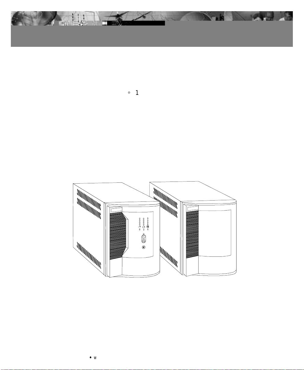
The Powerware95119 uninterruptible power system(UPS) protects
your sensitive electronic equipme nt frombasic powerproblems such as
power failures, power sags,power surges, brownouts, and line noise.
Poweroutagescan occur when youleastexpect it andpower quality
can be erratic. These powerproblemshavethe potential to corrupt
criticaldata, destroyunsaved work sessions, anddamage hardware—
causing hours oflost productivity and expensive repairs.
Withthe Powerware 5119,you c an safely eliminate the effects of power
disturbances and guard theintegrity ofyourequipment. ThePowerware
5119’s flexibility to handle anarray of network devices makes it the
perfect choice to protect your LANs,servers, andworkstations.
Figure1.Powerware 5119 andExternal Battery Cabinet
Becausean integral part ofpowerprotectionispower management
software,the Powerware 5119 comes fully equipped with a
communication port, serial cable, anda CDcontaining both LanSafe III
for networked systems and FailSafe IIIfor standalonesystems.
Powerware®5119 User’sGuide:www.powerware.com
1
Page 8

Powerware5119– One of the Best!
Providing outstanding performance and reliability, the Powerware
5119’s unique benefits include the following:
:
Advanced Battery Management (ABMZ) doubles battery service life,
optimizesrecharge time, andprovides a warningup to 60days before
the end of useful battery life.
:
Buck and Double Boost regulationensures consistent voltage to your
load by correctingvoltage fluctuations without using battery power.
:
Hot-swappable batteries simplify maintenance by allowing you to
replacebatteriessafelywithoutpowering downthe critical load.
:
Network TransientProtector guards your modem, faxmachine,and
othernetworkcommunications equipment from surges.
:
Start-on-battery compatibilityallowsyouto power upthe UPS even
if utilitypower is not available.
:
Optionalpower communication cards provide enhanced
communication capabilities for increased power protection and
longerbatterybackup times.
:
The Powerware 5119is back e d by worldwide agencyapprovals.
2
Powerware®5119 User’sGuide:www.powerware.com
Page 9

CHAPTER 2
INSTALLATION
This section explains:
:
Equipment inspection
:
Safetyprecautions
:
UPS installation
:
UPSrear panels
Inspecting the Equipment
If any equipment has beendamaged during shipment,keep the
shipping cartons andpackingmaterialsfor the carrier or placeof
purchase andfile a claimfor shippingdamage. If youdiscoverdamage
after acceptance, file a claimfor concealed damage.
To file aclaim for shipping damage orconcealeddamage: 1) File with
the carrier within15 days ofreceiptof the equipment; 2) Senda copyof
the damage claim within 15 days to your service representative.
Safety Precautions
Read thefollowing before youinstallthe UPS.
IMPORTANT SAFETY INSTRUCTIONS
SAVE THESE INSTRUCTIONS.Thismanual contains important instructionsthatyou
shouldfollowduringinstallation and maintenance of the UPS and batteries. Please
read allinstructionsbefore operatingtheequipmentandsavethismanual for future
reference.
Powerware®5119 User’sGuide:www.powerware.com
3
Page 10

Installation
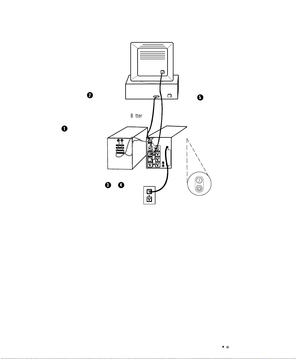
Installing the UPS
The following steps explain how to install the UPS. Figu re 3 on page 6
shows a typical installation only. See “UPS Rear Panels” on page 7 for
the rear panel ofeach model.
WARNING
:
ThisUPScontainsits own energy source (batteries).Theoutputreceptaclesmay
carrylivevoltage even when theUPSisnot connected to anACsupply.
:
Donot removeor unplug the input cord when the UPS is turned on. This removes
the safetyground from the UPS and the equipment connected to the UPS.
:
To reduce therisk of fire orelectric shock,installthis UPS in a temperature and
humiditycontrolled, indoor environment,freeof conductivecontaminants.
Ambienttemperaturemustnotexceed40C(104F).Donotoperatenear water
or excessive humidity (95% max).
:
The sumof earth leakage current from the load connected to the UPS must not
exceed1.5mA.
CAUTION
Asmallamountofarcingmayoccur whenconnecting an external battery to the UPS.
InsertthebatterycableintotheUPSbatteryconnectorquickly and firmly.
NOTE Donot makeunauthorizedchangestothe UPS;otherwise,damagemayoccur
to your equipmentand voidyourwarranty.
1. If the UPS has an external battery, connect it to the UPS as
shownin Figure 3 on page 6.
2. If youare installing power management software, connect your
computer to the UPS communication port using the supplied
communication cable.
Some power management software has a Load Segment feature
that allows you to control UPS output receptacles. If youplan
to use this feature, read the appropriate sections ofyourpower
management software manual before you install the UPS.
4
Powerware®5119 User’sGuide:www.powerware.com
Page 11
Installation
3. On 230V models, plug theUPS power cord into the input
connectoronthe UPS rear panel.
Customer-supplied power cords must correctly rated forthe
UPS (see “Specifications”on page 29).You can also usethe
power cord from the largest load if it iscorrectlyrated.
4. Plug the UPS power cord into a wall outlet or power source.
The UPS conducts a self-test and enters Standby mode. If a red
Site Wiring Fault or Battery Service indicator stays on, see
Table 11 on page 33.
Site Wiring Fault Indicator
Battery Service Indicator
Figure 2. Fault Indicators
NOTE Lowvoltagemodelsmaynotrecognize 50-Hz outlets. If the UPS does not
startwhenconnectedtoa 50-Hz outlet,unplugthe UPS.Pressandholdthe
button for 3 seconds to start the UPS on battery and reconfigure the nominal
On
inputvoltagetoeither100Vor 110V (see ”ConfigurationMode”onpage15).Turn the
UPSoff.Waitfor30seconds.ThenplugtheUPSintotheoutlet.
5. Plugthe equipment to be protected into the UPSoutput
receptacles.
DO NOT protect laserprinters withthe UPS because ofthe
exceptionally high powerrequirementsof the heating elements.
6. Start the UPS by pressing the On
The Power On indicator illuminates indicating that power is
available from the rear receptacles.
The installation iscomplete.To learn how tooperate the UPS,
see “Operation” onpage 11. Tochangethe factory-set defaults,
see “Configuration” on page 15.
NOTE The UPSchargesto90% in approximately4hours.However,itis
recommendedthatthe UPSchargefor 24 hours after installationorlongstorage.
Powerware®5119 User’sGuide:www.powerware.com
button as shownin Figure 3.
5
Page 12
Installation
2
Connect communication
cable from computer to
UPS (optional)
1
Connect battery to UPS
(if applicable)
3&4
Battery
Cabinet
5
Connect equipment
to UPS
UPS
6
Powerware®5119 User’sGuide:www.powerware.com
Page 13
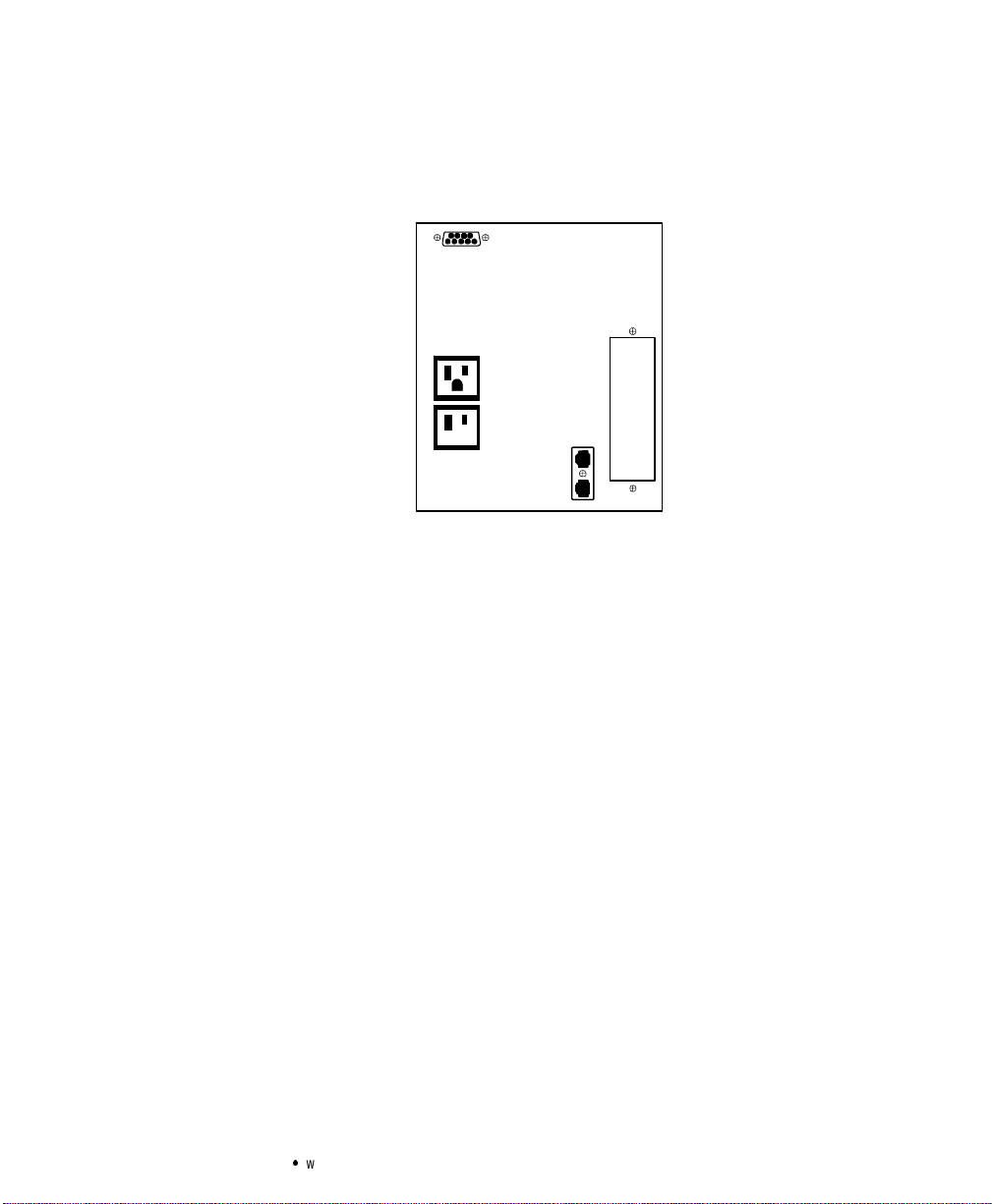
UPS RearPanels
Installation
This section shows the rear panels of all Powerware 5119 models.
Powerware®5119 User’sGuide:www.powerware.com
7
Page 14

Installation
8
Powerware®5119 User’sGuide:www.powerware.com
Page 15

Installation
Communication Port
Battery Connector
Load Segment 1
(Three IEC-320 Receptacles)
Load Segment 2
(Three IEC-320 Receptacles)
(Three IEC-320 Receptacles)
Figure 8. 2000-2400 VA,230VRearPanel
Communication Port
Battery Connector
Output Circuit Breakers
Load Segment 1
(Three IEC-320 Receptacles)
/
2
$
'
Load Segment 3
10A, IEC-320
Input Connector
Input Circuit Breaker
Option Slot
Network
T ransientProtector
16A, IEC-320
Input Connector
Input Circuit Breaker
Load Segment 2
(Three IEC-320 Receptacles)
Load Segment 3
(Three IEC-320 Receptacles)
Figure 9. 3000 VA,230VRearPanel
Powerware®5119 User’sGuide:www.powerware.com
Option Slot
Network
T ransientProtector
9
Page 16

Installation
10
Powerware®5119 User’sGuide:www.powerware.com
Page 17

CHAPTER 3
OPERATION
Thissectiondescribes:
:
Turning the UPS on and off
:
Starting the UPSon battery
:
Standby mod e
:
The UPS front panel and LEDs
:
Initiatingthe self-test
Turning the UPS On
After the UPS isconnected to a powersource, it conducts a self-testand
enters Standby mode. To turnon the UPS, press the On
front panel(showninFigure 10). ThePowerOn indicator illuminates
indicating that poweris available from the rear receptacles.
Starting the UPS onBattery
To turnon the UPS without usin gutility power, press and holdthe
On buttonfor three seconds.Whenthe UPS starts on battery, it does
not conduct a self-test toconservebattery power.
buttononthe
Turning the UPS Off
To turn off the UPS, press the Off
Powerware®5119 User’sGuide:www.powerware.com
11
Page 18

Operation
UPS FrontPanel
The UPS front panel LEDs indicate how theUPSis operating and also
alert you of potential powerproblems.Figure 10 shows the UPS front
panel indicators and controls.
Battery Charge LEDs
AC Input LEDs
Site Wiring Fault Indicator
T e st/AlarmResetButton
Load Level LEDs
Communication Indicator
On Button
Off Button
12
Powerware®5119 User’sGuide:www.powerware.com
Page 19

Operation
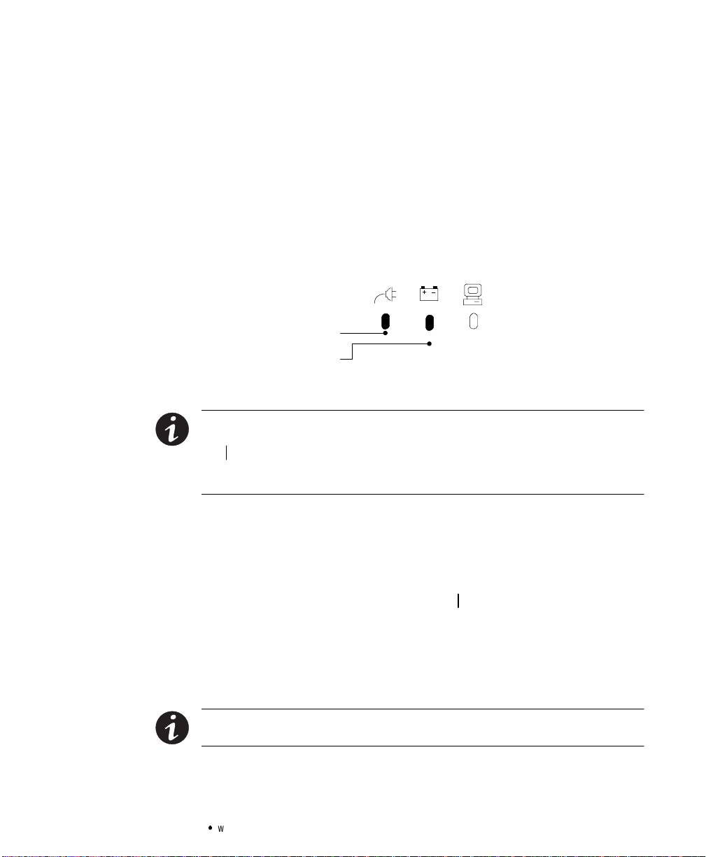
AC InputLEDs
The AC Input LEDs show information about the utility power coming
intotheUPS(seeFigure11).
Normal Utility Input (Buck and Single Boost)
Double Boost is on
Figure 11. AC InputLEDs (Normal Mode)
The second LED indicates that the UPSis operatingnormally from
utility power. The UPS is providing consistent voltage with the Buck
and SingleBoost feature.
The third LED indicates that the UPS is using the Double Boost feature
to automaticallycorrect voltage fluctuations.
If any ACInputLEDs are red, see page 34 formore information.
Battery ChargeLEDs
Powerware®5119 User’sGuide:www.powerware.com
13
Page 20

Operation
Load Level LEDs
The front panel displays the total load current or watts plugged into the
UPS (see Figure 13).
33-66% 5-33%66-100%
Figure 13. Load LevelLEDs (Normal Mode)
Each LED represents 1/3of a fullload rating.Whenthe UPS is
approximately fullyloaded (66-100%), all three LEDs illuminate.If the
load is 33-66% of UPS capacity, the third and fourth LED illuminate.
The last LED illuminates ifthe load isbetween 5%and 33%.
If any Load LevelLEDsare red, see page35 for more information.
Initiating the Self-Test
Press and hold the button for three seconds to initiatethe self-test.
During the test, individual LEDs illuminate as various parts of the UPS
arechecked. If theUPS finds a problem, an LEDindicateswhere the
problem is.For more information, see “Troubleshooting” on page 33.
NOTE AllthreeBatteryChargeLEDsshould be lit and theUPSmustnotbein
Batterymodeto perform the self-test.
14
Powerware®5119 User’sGuide:www.powerware.com
Page 21

CHAPTER 4
CONFIGURATION
This section explains:
:
Whyyou may want tochange factory defaults
:
How to r econfigure options
Why Change Factory Defaults?
Nominal Input Voltage
When the utility power consistently fluctuates, the UPS repeatedly
corrects theinputvoltageby switchingto battery powerwhenthe
nominal input range is:
:
Higher than +20%of 120V or 230V nominal
:
Lower than -30%of 120Vor 230Vnominal
:
Higher than +20%and lower than -30% of120V or230V nominal
You can configure the UPS to more closely match the nominal input
voltage by selecting a different input voltage or extending the input
voltage range. See Table 1 onpage 17 fora list of available options.
Other Settings
You can change theUPS default configurations for alarms andshutdown
parameters, including: timingfor the low battery alarm,the timedelay
for anunconditional shutdown, alarms for loss ofutility power orsite
fault, and controlling loads that use less than5% of the current when
the UPS ison battery. See Table 1 onpage 17 for alist of available
options.
Configuration Mode
When theUPS is in Configuration mode, the LEDs represent the
configuration options. The control buttons (On
are used to modify theUPS c onfiguration. Figure 14 showsthe LEDs
and Table 1 explains the corresponding options.
Powerware®5119 User’sGuide:www.powerware.com
button and button)
15
Page 22

Configuration
CAUTION
DONOTpresstheOff button whiletheUPSisinConfigurationmode;pressing
the Off
button removesallpowertoyourequipment.
1. Press and hold the On button and the button
simultaneously for one beep. The UPS switches to
Configuration mode.
2. Press the On
button to scroll through theoptions. Each time
youpressthe button,the UPS beeps. TheLED for the selected
option blinks (see Figure 14 and Table 1).
If you press the On
button and nothing happens, the UPS is
stillinOperationmode. Repeat Step1 for onebeep ONLYto
enter Configuration mode, and then performStep 2.
3. Press the
button ONCE to toggle theselected optionon or
off.The Power On indicator corresponds with the current
setting.
Repeat Steps 2and 3 foreach option.
4. Press the On
button and the buttonsimultaneously to
returnto O peration mode at any time. Scrolling pastthe last
LED also returns the UPS to Operation mode.
16
Power On Indicator
2
Press theOn button
to scroll tothenextoption.
3
Press theTest/Alarm Reset
button totoggleanoptiononoroff.
Figure 14. Using the Configuration Mode
LEDs
1
&
4
Press theOn andTest/Alarm Reset
buttons simultaneously to toggle between
Configuration and Operation mode.
Powerware®5119 User’sGuide:www.powerware.com
Page 23

Table 1.Configuration Mode LEDs andOptions
LED Option PowerOn
Indicator
Explanation
Configuration
120/230V Nominal
Input Voltage
110/220V Nominal
Input Voltage
127/240V Nominal
Input Voltage
120/230V Extended
Voltage Mode
Site Wiring Fault
Alarm
ON (default) Nominal input voltage onlow voltage models is 120V and on high voltage
models is 230V; all other nominal input voltages are disabled.
OFF* 120/230V is disabled; one of the other input voltage options is selected.
*This is the default formodels that are factory-configured for 100V or 208V (see
the rating ontheUPS rear panel).
ON Selecting this option changes the nominal input voltage on low voltage models
to 110V and to 220V for high voltage models.
OFF (default) 110/220V is disabled; one oftheotherinputvoltageoptionsisselected.
ON Selecting this option changes the nominal input voltage on low voltage models
to 127V and to 240V for high voltage models.
OFF (default) 127/240V is disabled; one oftheotherinputvoltageoptionsisselected.
ON The UPS accepts an input voltage within -35% to +20% of 120V or 230V
nominal input voltage before switching to battery.
OFF (default) The UPS acceptsaninput voltagewithin-30% to +20% of 120V or 230V
nominal input voltage before switching to battery.
ON (default) Alarmsoundswhenthepolarityoftheoutletisreversedortheground
connection is missing; have a qualified electrician repair the outlet wiring.
OFF* Alarm DOES NOT sound when the polarity of the outlet is reversed or the ground
connection is missing.
*Site Wiring Fault is not available for 100V or 208V models; OFF is the default.
Low Battery Alarm ON(default) Alarm sounds approximately 3 minutes before battery shutdown.
OFF Alarm sounds approximately 5 minutes before battery shutdown.
Powerware®5119 User’sGuide:www.powerware.com
17
Page 24

Configuration
OptionLED
Indicator
Shutdown Delay ON (default) 5-second delay before unconditional shutdown after the UPS receivesasignal
OFF 180-second delay beforeunconditional shutdown after the UPS receives a signal
AC Input Failure ON (default) Alarm sounds when there is an AC input failure.
OFF Alarm DOES NOT sound when there is an AC input failure.
Sleep Mode ON (default) When the UPS isonbattery and the load is drawing less than 5% of the current,
OFF Select this option if you want a load less than5% ofthecurrenttobeprotected
100/208V Nominal
Input Voltage
ON* Selecting this option changes the nominal input voltage on low voltage models
ExplanationPowerOn
from a computer via the communication port.
from a computer via the communication port. When this LED is not enabled, the
user canalsocreateanewdelaytimebyreconfiguringthecommunication port.
See“Communication Port Configurations” on page 25 for more information.
the UPS shuts down the load. This feature conserves battery power.
by batterypower .
to 100V and to 208V on high voltage models.
*This is the default forfactory-configured100V or 208V models (see the rating
label on theUPS rear panel).
OFF (default) 100/208V is disabled; one oftheotherinputvoltageoptionsisselected.
100/208V Extended
Voltage Mode
Reset Defaults ON (default) All factory-set defaults areactive.
ON Select this option to extend the input voltage within-25% to +25% of 100V or
208V nominal input voltage before switching to battery (available on units that
were specifically ordered with this option).
OFF (default) The UPS acceptsaninput voltagewithin-20% to +20% of 100V or 208V
nominal input voltage before switching to battery.
OFF One or more factory-set defaults have been changed.
18
Powerware®5119 User’sGuide:www.powerware.com
Page 25

CHAPTER 5
UPS MAINTENANCE
This section explains how to:
:
Care for the UPS and batteries
:
Replace the batteries
:
Test ne w batteries
:
Recycle used batteries
UPS and Battery Care
Forthe best preventive maintenance,keep the area around theUPS
clean and dust-free.If the atmosphere is verydusty, cleanthe outside of
the system with a vacuum cleaner.
Forfullbattery life, keep theUPSat anambienttemperature of
25°C (77°F).
Storing theUPS andBatteries
If you store the UPSfor a long period, recharge the battery every
12 months by plugging the UPS into a power outlet. The UPS charges to
90% in approximately4 hours. However, it is recommendedthat the
UPS charge for 24 hours after long storage.
When to Replace Batteries
When the Battery Service indicator illuminates, the batteries may need
replacing (see Figure 10on page 12).Conduct a self-test by pressing the
button. If the indicator stays on, contact your service representative
to order new batteries.
Powerware®5119 User’sGuide:www.powerware.com
19
Page 26

UPS Maintenance
Replacing Batteries
The hot-swappablebattery featureallows you to replace theUPS
batteries easily without turning the UPS off or disconnecting the load.
If you prefer to remove input power to change the battery: 1) Press the
Off
internal processor shuts down before you disconnect the battery.
Consider allwarnings, cautions,and notes before replacing batteries.
:
:
Pullthebatteryout onto a flat, stable surface.Thebatteryisunsupportedwhenyou
pullitoutof the UPS.
button and then unplug the UPS; 2) Wait 60 seconds while the
WARNING
Batteriescanpresentariskofelectrical shockor burn from high short circuit
current.Thefollowingprecautions should be observed: 1) Removewatches,rings,
or other metal objects;2)Usetoolswith insulated handles;3)Donotlaytoolsor
metalpartsontop of batteries.
ELECTRICENERGYHAZARD.Donotattempt to alter any battery wiringor
connectors.Attempting to alter wiring can cause injury.
CAUTION
20
NOTE Whenthe UPS isonline,allthreeBatteryChargeLEDsshould be lit before
hot-swappingthebatteries.DONOT DISCONNECT the batteries whiletheUPSisin
Batterymode.
Powerware®5119 User’sGuide:www.powerware.com
Page 27

How toReplace ExternalBatteries
Use the following steps to replace external batteries:
1. Unplug thebattery cable from the UPSand remove the old
battery. See “Recycling the Batteries” onpage 24for proper
disposal.
2. Plugthe ne w battery cabinet into the UPS asshown in
Figure 15.
Battery CabinetUPS
Battery
Connector
Plug thebatterycable
into thebattery
connector
UPS Maintenance
Figure 15. External Battery Connections (120VModelShown)
Powerware®5119 User’sGuide:www.powerware.com
21
Page 28

UPS Maintenance
How toReplace InternalBatteries
Use the following steps to replace internal batteries:
1. Pullthefrontpanelforwardand snap into placeas shown.
22
Powerware®5119 User’sGuide:www.powerware.com
Page 29

1000 VA Models
UPS Maintenance
4. Remove the old battery. See “Recycling the Batteries” on
page 24 for proper disposal.
5. Connect the new batteries to the UPSas shown inFigure16
and reinstall.
RedCablefrom UPS
PositiveTerminal
BlackCable fromUPS
NegativeTerminal
RedConnector
from UPS
BlackCable fromUPS
1500 VA Models
Negative
Terminal
(Black)
Figure 16. Internal Battery Connections
Testing New Batteries
Press and hold the button for three seconds to initiatea self-test.
After the test isfinished,the red Battery Service indicator should turn
off a nd the Battery Charge LEDs should show a charge. If the Battery
Serviceindicator stayson,check the battery connections.See the
troubleshooting guide on page 33 or callyour service representative if
the problem persists.
Powerware®5119 User’sGuide:www.powerware.com
RedBattery Connector
23
Page 30

UPS Maintenance
Recycling the Used Battery
Contactyourlocal recycling orhazardous wastecenter for information
on proper disposal of the usedbattery.
:
Donot disposeofbatteryor batteriesina fire.Batteriesmayexplode.Proper
disposalofbatteriesisrequired. Refer to your local codes for disposal
requirements.
:
Donot open or mutilate the battery or batteries. Releasedelectrolyteisharmful
to the skinand eyes.Itmaybetoxic.
Donot discardtheUPSorthe UPS batteriesinthe trash.Thisproductcontains
sealed,lead-acid batteries and must be disposed of properly.Formoreinformation,
contactyourlocalrecyclingor hazardous wastecenter.
WARNING
CAUTION
24
Powerware®5119 User’sGuide:www.powerware.com
Page 31

CHAPTER 6
ADDITIONAL UPS FEATURES
Thissectiondescribes:
:
UPS communication capabilities
:
The Network Transient Protector
:
Load segments
:
Optionmodules
Communication Port Configurations
To establishcommunication between theUPS and a computer, connect
your computer to the UPS communication port using the supplied
communication cable.
To prevent damagetoyourequipment,connect only a factory-suppliedcableora
cablebuilttofactoryspecifications(seeTable 2) to the communicationport.A
standardserialcablemaydamageyourcomputer.
Whenthe communication cableis installed,power management
software canexchangedata with theUPS.The softwarepolls the UPS
for de ta iled informationon the status of thepower environment. If a
power emergencyoccurs,thesoftware initiates thesavingof all data
and an orderly shutdown of the equipment.
CAUTION
Communication Indicator
Whenthe UPS receives a command from the computer to establish
communication, the Communicationindicator onthe UPS frontpanel
illuminates (see Figu re 10 onpage 12). Whendata is transferring, the
Communication indicatorflashes.
Powerware®5119 User’sGuide:www.powerware.com
25
Page 32

Additional UPS Features
Pin Out
As shown in Table 2, Pins 1 and 2 operate intwo modes: BasicAlarms
mode and Serial Datamode. Basic Alarms mode hasAC fail alarm and
output shutdown. Serial Data mode is UPS Code II compliant.
The system always starts in Basic Alarmsmode.Whenserialdata is
received at Pin 1, the function ofPin1 and Pin 2 changesto Serial Data
mode.
If serial data hasnot been received before going to batterypower, serial
communication is disabled until AC input power returns.
6789
12345
Figure 17. Communication Port
Table 2.CommunicationPort Configuration
Pin SignalType Function
1
2
3 Output: Open collector transistor ON, 50 mA, 40 Vdc rating AC Input failure
4 SignalCommon Signal Common
5 Output: Open collector transistor ON, 50 mA, 40 Vdc rating Impending low battery
6 Input: RS-232 RTS Plug-and-play software enable trigger (activates
7 Input: Relay contact or RS-232 level Remote Emergency Power-Off: UPS total output can
8 Output: 8 to 25 Vdc, 5W constant power (0.63A max. @ 8V) Auxiliary Control Power
9 Chassis Connection to chassis
26
Basic Alarms Mode-Input: RS-232 level high (+12V) pulse
4 to5seconds
Serial Data Mode - Input: RS-232 data RS-232 serial communication input. 1200 baud,
Basic Alarms Mode-Output: RS-232 level high (+12V) AC Input failure
Serial Data Mode - Output: RS-232 data RS-232 serial communication output. 1200 baud,
Remote UPS off. In absence of AC power, output is
turned offuntilnormal AC power returns
8 bits,Noparity, 1 stop bit, 1 start bit
8 bits,Noparity, 1 stop bit, 1 start bit
when pin changes from +12V to -12V)
be keptoffwith low signal or closing relay contact
Powerware®5119 User’sGuide:www.powerware.com
Page 33

Network Transient Protector
The Network Transient Protector, shown in Figure18, is located onthe
rearpanel and has jackslabeled IN andOUT. This feature
accommodatesa single RJ -45 (10BaseT) network connector.
Low voltage models can alsoaccommodate an RJ-11 telephone
connectorthatprovides protection for modems, faxmachines,or other
telecommunicationsequipment.As with most modemequipment, itis
not advisable to use thisjack in digital PBX (Private Branch Exchange)
environments.
Connect the input connector of the equipment you are protecting to the
jack labeled IN.Connect theoutputconnectorto the jacklabeled OUT.
Additional UPS Features
IN OUT
Load Segments
Option Modules
IN
OUT
NETWORKTRANSIENTPROTECTOR
Figure 18. Network TransientProtector
Load segmentsare sets ofreceptacles thatcan be turned onindividually
using powermanagementsoftware. Forexample,during a power
outage,youcan keep key pieces ofequipment running while you turn
off other equipment.Thisfeatureallowsyou to save batterypower. See
yourpower managementsoftwaremanualfor details.
Optionmoduleshelp your UPS communicate in a varietyof networking
environments and are installed inthe UPS option slot. See the manual
that accompanieseach module for more information, or contact your
salesrepresentative.
Powerware®5119 User’sGuide:www.powerware.com
27
Page 34

Additional UPS Features
28
Powerware®5119 User’sGuide:www.powerware.com
Page 35

CHAPTER 7
SPECIFICATIONS
Thissectionprovides thefollowing specificationsfor the Powerware
5119 mode ls:
:
Electrical input andoutput
:
W eights and dimensions
:
Environmental and safety
:
Indicatorsand controls
:
Battery
Table 3.ModelList
120V Models 230V Models
UPS Models PW5119 1000
PW5119 1500
PW5119 2000
PW5119 2400
PW5119 3000
PW5119 1000i
PW5119 1500i
PW5119 2000i
PW5119 2400i
PW5119 3000i
Table 4.Electrical Input
120V Models 230V Models
NominalVoltage 120V default; 100, 110, 120, 127V selectable 230V default; 208, 220, 230, 240V selectable
VoltageRange -30% to +20% at full load for nominal voltage; -35% to+20% user-selectable, extended range
NominalFrequency 60 Hz; 50/60 if 100V or 110V selected 50/60 Hz
Noise Filtering MOVs and line filter for normal andcommon mode noise
Connections 1000-1500 VA: 6-ft.powercordwith5-15plug
2000 VA: 6-ft.powercordwith5-20plug
2400-3000 VA: 6-ft.powercordwith5-30plug
Powerware®5119 User’sGuide:www.powerware.com
1000-2400 VA: 10A,IEC-320 input connector
3000 VA: 16A,IEC-320 input connector
29
Page 36

Specifications
Table 5.Electrical Output
120V Models 230V Models
PowerLevels (ratedat
nominalinputs)
RegulationOnline -10% to +6% of nominal voltage (-15% to +10% using extended range)
RegulationOn-Battery
(NominalVoltage±5%)
VoltageWaveform Sine wave; <3% distortion with linear load
Overcurrent Protection Online: Branch-rated orresettablecircuit breaker;
OutputReceptacles 1000-1500 VA: Six5-15
PW5119 1000: 1000VA,670W
PW5119 1500: 1440VA,960W
PW5119 2000: 1920VA,1400W
PW5119 2400: 2400VA,1600W
PW5119 3000: 2880VA,2250W
120V for 110, 120, 127V; 100V for 100V 230V for 220, 230, 240V; 208V for 208V
On-Battery: Active current limit and short circuit protection
2000 VA: Six5-15,Two 5-20
2400-3000 VA: Six5-15, One 5-30
PW5119 1000i: 1000VA,670W
PW5119 1500i: 1500VA,960W
PW5119 2000i: 2000VA,1400W
PW5119 2400i: 2300VA,1600W
PW5119 3000i: 3000VA,2250W
1000-1500 VA: Six IEC-320
2000-3000 VA: NineIEC-320
Table 6.WeightsandDimensions
120V Models 230V Models
UPS Dimensions
(WxHxD)
UPS Weights 1000 VA: 43lb(20kg)
7 x8.8x17.1inches
(17.8 x 22.3 x43.4cm)
1500 VA: 57lb(26kg)
2000 VA: 32lb(15kg)
2400 VA: 36lb(16kg)
3000 VA: 41lb(19kg)
BatteryDimensions
(WxHxD)
Battery Weights PW5119 1048BP: 47lb(21kg) PW5119 1748BP: 70 lb (32 kg)
30
7 x8.8x17.1inches
(17.8 x 22.3 x43.4cm)
Powerware®5119 User’sGuide:www.powerware.com
Page 37

Specifications
Table 7.Environmental and Safety
120V Models 230V Models
OperatingTemperature 0°C to 40°C (32°F to 104°F); UL tested25°C (77°F)
StorageTemperature -20°C to 60°C ( -4°Fto140°F)
Relative Humidity 5-95% noncondensing
OperatingAltitude Up to 3,000 meters above sea level
AudibleNoise Less than45dBA typical
SurgeSuppression IEEE 587/ANSI C62.41 Category B
SafetyConformance UL 1778; CAN/CSA C22.2, No. 107.1 UL 1778; CAN/CSA C22.2, No. 107.1;
EN 50091-1 and IEC 60950
Safety Markings UL,CSA UL,CSA,CE
EMC FCC,VCCI EN 50091-2
Table 8.Indicators and Controls
SerialCommunication Intelligent serial communication to provide alarms with history, measured parameters, self-test,
and many other features; contact yourauthorizeddealerforUPS/computer communication
software options
Interface Ergonomic Indicators: WiringFault,Battery Service, Communication, Operation, System Normal
Bar Graphs: InputLevel,Battery Charge Level, % Load
ContactClosures AC Input Failure, Low Battery
Table 9.Battery
120V Models 230V Models
Configuration 1000-1500 VA: internalbatteries
2000-3000 VA: externalPW51191048BP
Voltage 24 Vdc for internal; 48 Vdc for external
Type Sealed, maintenance-free, valve-regulated, lead-acid
Charging Advancedchargingforfasterrecovery;approximately4hoursto90%usablecapacityatnominal
line and nosupplementary power supply load
Monitoring Advanced monitoring for earlier failure detection and warning
Powerware®5119 User’sGuide:www.powerware.com
1000-1500 VA: internalbatteries
2000-3000 VA: externalPW51191748BP
31
Page 38

Specifications
Table 10.Battery Run Times (in Minutes)
Load(VA) 1000 Model 1500 Model 2000 Model 2400 Model 3000 Model
300 49 79 92 162 162
500 21 38 55 97 97
700 14 17 34 62 62
1000 8 6 24 43 43
1500 8 13 23 23
2000 8 16 16
2400 13 13
3000 7
NOTE
Battery times are approximate and vary depending on theloadconfigurationandbatterycharge.
32
Powerware®5119 User’sGuide:www.powerware.com
Page 39

CHAPTER 8
TROUBLESHOOTING
This section explains:
:
UPS alarms and conditions
:
How to silence an alarm
:
Service and support
Audible Alarms andU PS Conditions
The UPS has anaudiblealarm featureto alert you ofpotentialpower
problems. Use Table 11 to determine and resolve the UPS alarms and
conditions.
Silencing an Audible Alarm
To silence the alarm foran existing fault,pressthe button.If UPS
statuschanges, thealarm beeps, overridingthe previousalarmsilencing.
Table 11.Troubleshooting Guide
AlarmorCondition Possible Cause Action
The Power On indicator is
not on; theUPS will not
start.
The UPS switches
frequently between battery
and AC input.
Powerware®5119 User’sGuide:www.powerware.com
A circuit breaker or an input
fuse ontherearpanelisopen.
The line cordisnotconnected.
The wall outlet is dead. Have a qualified electrician test and repair theoutlet.
The UPS may be unable to
recognize a100V, 50-Hz wall
outlet.
A battery fuse or circuit breaker
is open.
Input voltage in your areadiffers
from the UPS nominal.
Push thecircuit breakerbuttonorreplacethefuse(see“UPS
Rear Panels” on page 7).
Connect the line cord.
See “Specifications” on page 29 to verify that your UPS
accepts 100V nominal input.
Unplug the UPS. Start the UPS on battery andreconfigurethe
nominal input voltage for 100V (see ”Configuration Mode” on
page 15). Turn off the UPS for 30 seconds. Plug the UPS into
the outlet.
Contact your service representative.
Change the UPS input voltage to match your local voltage; see
“Configuration Mode” on page 15.
33
Page 40

Troubleshooting
ActionPossible CauseAlarmorCondition
The Low Battery Alarm
does not giveenough
warning.
AC input high
AC input low
Site Wiring Fault
Low Battery Charge
The batteries needchargingor
service.
The Low Battery Alarm is not
set appropriately.
The AC input voltage is too
high. The UPS is running on
battery power.
The line voltage istoolow.The
UPS is running on battery
power.
Ground wire connection does
not exist in thewall outlet or
the line andneutralwires are
reversed inthewalloutlet.
The batteryisrunninglow. 3 to5minutes orlessofbatterypowerremains (depending on
Plug theUPS into a wall outlet for 24 hours to charge the
battery.Afterchargingthebattery, press and hold the
button for 3seconds;thenchecktheBatteryService
indicator.
If theBattery Service indicator is stillon,see“UPS
Maintenance” on page 19toreplacethebattery.
Change the alarm setting. See “Configuration Mode” on
page 15.
Correct the input voltage, if possible. The UPS continues to
operate onbatteryuntilthebatteryiscompletelydischarged.
If the condition persists, theinputvoltageinyourareamay
differ from the UPS nominal. Change the UPS input voltage to
match your local voltage (see “Configuration Mode” on
page 15).
Correct the input voltage, if possible. The UPS continues to
operate onbatteryuntilthebatteryiscompletelydischarged.
If the condition persists, theinputvoltageinyourareamay
differ from the UPS nominal. Change the UPS input voltage to
match your local voltage (see “Configuration Mode” on
page 15).
Have a qualifiedelectriciancorrectthe wiring.
T odisable this alarm, see “Configuration Mode” on page 15.
load andbatterycharge).
Prepare for ashutdown. Save your work and turn offyour
equipment.
34
Powerware®5119 User’sGuide:www.powerware.com
Page 41

Troubleshooting
ActionPossible CauseAlarmorCondition
The batterymay befully
Battery Service
Battery Service
Overload
discharged because ofalong
storageperiodorfailing
because ofage.
The batteryisnotconnected
correctly.
The DC voltage is high; the
alarm does not clear.
Power requirements exceed
UPS capacity or the load is
defective.
Service and Support
If you have anyquestions orproblems withthe UPS, call your
Distributor
and ask fora UPS technical representative.
In the United States
In Canada
All other countries
or the
Help Desk
1-800-365-4892
1-800-461-9166
1-919-870-3149
Plug theUPS into a wall outlet for 24 hours to charge the
battery.Afterchargingthebattery, press and hold the
button for 3seconds;thenchecktheBatteryService
indicator.
If theBattery Service indicator is stillon,see“UPS
Maintenance” on page 19toreplacethebattery.
Check connections or call your service representative.
Contact your service representative.
Remove some of the equipment from the UPS. Youmay need
to obtainalargercapacityUPS.
Local
at one of the following telephone numbers
Pleasehave the followinginformation ready whenyoucall the Help
Desk:
:
Model number
:
Serial number
:
Version number (ifavailable)
:
Date offailure or problem
:
Symptoms of failure or problem
:
Customer return address and contactinformation
Powerware®5119 User’sGuide:www.powerware.com
35
Page 42

Troubleshooting
If r epair is required, you will be given a Returned Material
Authorization (RMA) Number. This number must appear on the outside
of the package and onthe Bill Of Lading (ifapplicable). Use the original
packagingor requestpackagingfromthe Help Deskor distributor.Units
damaged in shipment as a resultof improper packaging are not covered
underwarranty. Areplacement orrepairunitwillbe shipped, freight
prepaidfor all warrantied units.
NOTE Forcriticalapplications,immediate replacement may be available.Callthe
Help Desk
for the dealer or distributor nearestyou.
36
Powerware®5119 User’sGuide:www.powerware.com
 Loading...