

Page 1

02/15/01
Powerware®3115
User’s Guide
300-650 VA
www.powerware.com
Page 2

Powerware is aregistered trademark of Powerware Corporation.
E
Copyright 1999 Powerware Corporation, Raleigh, NC. All rights reserved. No part of this document may be reproduced
in any way withouttheexpresswrittenapprovalof PowerwareCorporation.
Page 3

Class B Statement for FCC and ICES
NOTE This equipmenthas been tested and found to comply with the limits for a Class B device pursuantto Part 15 of
FCC Rules. These limits are designed to provide reasonable protection against harmful interference when this equipment is
operated in a residential environment. This equipmentgenerates,uses, and can radiate radio frequency energy and, if not
installed and used in accordance with the instruction manual, may causeharmfulinterference to radio communications.
However, there is no guarantee that interference willnot occur in a particularinstallation. If thisequipment does cause
harmfulinterference toradio or television reception,whichcan be determinedby turningthe equipmentoff and on, the
user is encouraged to tryto correctthe interference by one ormoreof the following measures:
S
Reorient or relocate the receivingantenna.
S
Increase the separation between the equipment and the receiver.
S
Connectequipmentinto a n outleton a circuit different fromthatto which the receiver is connected.
S
Consultthedealer or an experienced radio/TVtechnician for help.
S
Ensure that mounting screws, connectorattachment screws, and all ground wiresaresecuredand tight.
Changes or modifications not expressly approved by the party responsible for compliance could void the user’s authority to
operate the equipment.
For Users in Canada
This Class B Interference Causing Equipment meetsall requirements of the Canadian Interference Causing Equipment
Regulations ICES-003.
Cet appareil numérique de la classe A respecte toutes les exigences du Reglement sur le matériel brouilleur du Canada.
Requesting a Declaration of Conformity
The EC Declaration of Conformityis available upon request forproducts with a CE mark. For copies of the EC
Declaration of Conformity, contact:
Powerware Corporation
Koskelontie 13
FIN-02920 Espoo
Finland
Phone: +358-9-452661
Fax: +358-9-452-66395
EMC Statement
Some configurations are classified under EN50091-2 as “Class-A UPS for Unrestricted Sales Distribution.” For these
configurations, the following applies:
WARNING This is a Class A-UPS Product. In a domestic environment, this productmay cause radiointerference, in which
case, the usermay be required to take additionalmeasures.
Page 4
Special Symbols
The followingare examples of symbols used on the UPS to alert you to important information:
CCCCAAAAUUUUTTTTIIIIOOOONNNN
RiskofElectricShock
DoNotOpen Cover
CAUTIONToreduce the risk of electricshock,
Donot remove cover (or back)
Nouser-serviceable parts inside
Refer servicing to the factory
RISKOF ELECTRIC SHOCK - Indicates that a risk of electric shock is present and the
associated warning should be observed.
CAUTION: REFERTO OPERATOR’S MANUAL - Refer to your operator’smanual for
additional information, such as importantoperating and maintenance
instructions.
This symbolindicates that you should not discardthe UPS or the UPS batteries
in the trash. The UPS may contain sealed, lead-acid batteries. Batteries must be
recycled.
Page 5

TABLE OF CONTENTS
1 Powerware 3115 –One of the Best! 1..................................
2 Installation 3.....................................................
InspectingtheEquipment 3.......................................................
SafetyPrecautions 3............................................................
Installing the UPS 4.............................................................
UPSRear Panels 6..............................................................
3 Operation and Configuration 9.......................................
Turning the UPS On 9............................................................
Startingthe UPSon Battery 9...................................................
Turning the UPS Off 9...........................................................
StandbyMode 10...............................................................
Howto SetDIP Switches 10........................................................
Communication Port Configuration 11.................................................
4 UPS Maintenance 13...............................................
UPSand BatteryCare 13..........................................................
Storingthe UPSand Batteries 13..................................................
ReplacingBatteries 14...........................................................
Testing NewBatteries 17.........................................................
Recycling the Used Battery 17......................................................
5 Specifications 19..................................................
6 Troubleshooting 23.................................................
SiteWiringFault (120VModelsonly) 23...............................................
AudibleAlarmsand UPSConditions 23................................................
Silencing an Audible Alarm 23....................................................
Service and Support 25...........................................................
Powerware®3115 User’sGuideSwww.powerware.com
i
Page 6

Table of Contents
ii
Powerware®3115 User’sGuideSwww.powerware.com
Page 7

CHAPTER 1
POWERWARE 3115 – ONE OF THE BEST!
The PowerwareR3115 uninterruptible power system (UPS) protects
your sensitive electronic equipment from three basic power problems:
power failures, powersags, and power surges.
Poweroutages can occurwhen youleast expect it and powerquality can
be erratic.These power problems have the potential to corrupt critical
data, destroy unsavedwork sessions, and damage hardware — causing
hours of lost productivity and expensive repairs.
Withthe Powerware 3115, you can safely eliminate the effects of power
disturbances and guard theintegrityof your equipment. Ideal for PCs,
workstations, point-of-sale systems, network nodes, and similar
equipment, the Powerware 3115 provide s cost-effective power
protection.
Becausean integralpart of power protection is power management
software,the Powerware 3115 comes fully equipped with a
communication port,serial cable, anda CDcontainingboth LanSafeIII
for networked systems and FailSafe III for standalonesystems.
Providingoutstanding performance and reliability, the Powerware 3115’s
unique benefits include the following:
S
Compactdesign conserves valuable space andmakes the UPS easyto
install.
S
User-replaceable batteriesextend the service life of yourUPS.
S
The Site WiringFault indicator immediately informs you of wall
outlet wiringproblems (available on120V models only).
S
Audible alarms alert you of any fault conditions.
S
Start-on-battery allows you to power up the UPS even if utility power
is not available.
S
The Powerware3115 isback e d by worldwideagency approvals.
Powerware®3115 User’sGuideSwww.powerware.com
1
Page 8
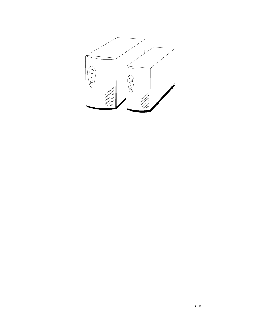
Powerware3115 – ONE OF THE BEST!
650 VA
300 VA and420 VA
Figure 1. Powerware3115
2
Powerware®3115 User’sGuideSwww.powerware.com
Page 9

CHAPTER 2
INSTALLATION
This section explains:
S
Equipment inspection
S
Safetyprecautions
S
UPS installation
S
UPSrear panels
Inspecting the Equipment
If any equipment has been damaged during shipment, keep the shipping
cartonsand packing materials for the carrier or place of purchase and
file a claimfor shippingdamage. If you discoverdamage after
acceptance,file a claim forconcealed damage.
To file a claimfor shippingdamage or concealeddamage: 1) File with
the carrier within 15 daysof receipt of theequipment;2) Send a copy of
the damage claim within 15 days to your service representative.
Safety Precautions
Read the following precautions before you installthe UPS.
IMPORTANT SAFETY INSTRUCTIONS
SAVE THESEINSTRUCTIONS.Thismanualcontains important instructions that you
shouldfollowduring installation and maintenance ofthe UPSand batteries.Please
read all instructions beforeoperating the equipment andsave thismanualfor future
reference.
Powerware®3115 User’sGuideSwww.powerware.com
3
Page 10

Installation
Installing the UPS
The following steps explain how to install the UPS. See “UPS Rear
Panels” on page 6 for the rear panel of each model.
WARNING
S
ThisUPS contains its ownenergy source(batteries).Theoutput receptaclesmay
carrylive voltage evenwhen theUPS is notconnected toan ACsupply.
S
Donot removeor unplugthe inputcord whenthe UPSisturned on. This removes
the safety groundfrom theUPS andthe equipmentconnected tothe UPS.
S
To reduce the riskof fireor electricshock,install thisUPS in a temperature and
humiditycontrolled,indoorenvironment,freeofconductivecontaminants.Ambient
°
temperaturemust notexceed 40
excessive humidity (95% max).
1. If you are installing the power management software, connect
your computer to the UPS communication port using the
supplied communication cable.
C(104°F).Donot operate nearwater or
NOTE Ifyou needto change the factory-setdefaultsfor output voltageorutility
powerrange, see“Howto Set DIP Switches” on page 10 beforeinstalling the UPS.
2. On 230V models, plugthe UPS power cord into the input
connector on the UPS rear panel.
3. Plug the UPS power cord into a wall outlet or other power
source.
4. Plugthe equipment to be protected into the UPS output
receptacles.
DO NOT protectlaser printers with the UPSbecause of the
exceptionally highpower requirements of theheating elements.
4
Powerware®3115 User’sGuideSwww.powerware.com
Page 11

5. Start the UPS by pressing the button as shownin Figure 2.
The Power On indicator illuminates indicating that power is
available from the rearreceptacles.
On/Off Button
T est/AlarmReset Button
Figure 2. Powerware 3115 Front Panel
Installation
Power On Indicator
The UPSconducts a self-test and entersNormal mode. If the
alarm beeps, consult“Troubleshooting” on page 23.
NOTE The UPSchargesto 90%in approximately12 hours.However,itis
recommendedthat theUPS chargefor 24hours afterinstallationor longstorage.
Powerware®3115 User’sGuideSwww.powerware.com
5
Page 12

Installation
UPS Rear Panels
This sectionshows the rear panels of all Powerware 3115 models.
Communication Port
10A, Resettable
Circuit Breaker
Power Cord with
5-15 Plug
Figure 3.PW3 300 andPW3 420 Rear Panel
Communication Port
Site Wiring Fault Indicator
DIP Switches
T wo5-15Output
Receptacles
Site Wiring Fault Indicator
DIP Switches
10A, Resettable
Circuit Breaker
Four 5-15 OutputReceptacles
Power Cord with
5-15 Plug
Figure 4.PW3 650 RearPanel
6
Powerware®3115 User’sGuideSwww.powerware.com
Page 13

Communication Port DIP Switches
Installation
10A, IEC-320 Input Connector
with Fuse
Figure 5. PW3300i and PW3 420i Rear Panel
Communication Port
Four IEC-320 Output
Receptacles
T woIEC-320 Output
Receptacles
DIP Switches
10A, IEC-320, Input Connector
with Fuse
Figure 6. PW3 650i Rear Panel
Powerware®3115 User’sGuideSwww.powerware.com
7
Page 14

Installation
8
Powerware®3115 User’sGuideSwww.powerware.com
Page 15

CHAPTER 3
OPERATION AND CONFIGURATION
Thissection covers:
S
Turning the UPS on and off
S
Starting the UPS on ba ttery
S
Standby mode
S
How to set DIP switches
S
Configuring the communication port
Turning the UPS On
To turn on the UPS,p ress the button on the front panel (shownin
Figure 2 on page 5). After the UPS is turned on, it conducts a self-test
and enters Normal mode. The Power On indicator illuminates indicating
that power is availablefrom therear receptacles.
Starting the UPS on Battery
To turn on the UPS without using utility power ,press and hold the
button for three seconds.When the UPS starts on battery, it does not
conducta self-test to conserve battery power.
NOTE The UPSdoesnot automatically detectthe inputfrequency whenstartingon
battery.Thedefaultfrequencyfor120Vmodelsis60 Hz;the defaultfrequencyfor 230V
modelsis50 Hz.
Turning the UPS Off
To turn off the UPS, press the button onthe frontpanel and then
unplug the UPS from the power source. If you do not unplug the UPS, it
remainsin Standby mode.
Powerware®3115 User’sGuideSwww.powerware.com
9
Page 16

Operation and Configuration
Standby Mode
When the UPS is turned off and plugged into a wall outlet or other
power source, theUPS is inStandby mode. Thebattery recharges when
necessary and the Power On indicatoris off, indicating that poweris not
available from the rearreceptacles.
How to Set DIP Switches
The DIPswitches onthe rear panelof each unit(see Figure 7) are used
to configure the output voltage and utility power range.
1. The UPS must be completely shutdown.
Turn the UPS off by pressing the
and then unplug the UPS.
2. Set theDIP switchesaccordingto the DIP switchconfigurations
in Table 1.
3. Plug the UPS into a wall outlet or other power source and press
the
buttononthefrontpanel
button to turn the UPS on.
10
UPS Rear Panel
DIP Switches
DIPSwitchDetail
4321
OFF
ON
Figure 7. DIP Switch Location
Powerware®3115 User’sGuideSwww.powerware.com
Page 17

Table 1.DIP SwitchSettings
p
g
y
p
g
y
Output Voltage
Utility Power
Range
Output Voltage
Utility Power
Range
*Default position
110V ON OFF
120V* OFF OFF
127V OFF ON
103V - 142V* OFF OFF
98V - 142V
93V - 142V OFF ON
88V - 142V ON OFF
220V ON OFF
230V* OFF OFF
240V OFF ON
196V - 260V* OFF OFF
186V - 260V
176V - 260V OFF ON
166V - 260V ON OFF
Operation and Configuration
120V Models
DIPSwitch1 DIPSwitch2 DIPSwitch3 DIPSwitch4
ON ON
230V Models
DIPSwitch1 DIPSwitch2 DIPSwitch3 DIPSwitch4
ON ON
Communication Port Configuration
To establish communication between the UPSand a computer, connect
your computer to the UPS communication port using the supplied
communication cable.Use only thefactory-supplied cable and software.
See Table 2 for detailed information.
CAUTION
To preventdamageto yourequipment,connectonlyafactory-suppliedcableor acable
builtto factoryspecifications (seeTable 2) to the communication port.A standard
serialcablemay damageyour computer.
Powerware®3115 User’sGuideSwww.powerware.com
11
Page 18

Operation and Configuration
Whenthe communication cable is installed, power management
software can exchange data withthe UPS.The software polls the UPSfor
detailed information onthe status of the powe r e nvironment. I f a power
emergency occurs,the softwareinitiatesthe savingof all data and an
orderlyshutdown of the equipment.
6789
12345
Figure 8.Communication Port
Table 2. Communication Port Configuration
PinNumber SignalType Function
1 Input: RS-232 high level signal for>0.4
seconds
2 Output: Open closing tologic ground pin4 ImpendingLow Battery: Indicates thebattery has less than 2
3 Output: Open closing tologic ground pin4 ACInput Failure: Indicates absenceof normal AC input
4 Signal Return Logic Ground
5 Output: RS-232 levellow Impending Low Battery: Indicates the batteryhas less than2
6 Output: RS-232 levelhigh AC InputFailure: Indicates absence of normal AC input
7 NotUsed NotUsed
8 NotUsed NotUsed
9 Chassis Ground (connected topin 4) Chassis Ground
Conditional PowerOff: In absence ofAC power,output is
turned off untilnormal AC power returns
to 5 minutes of backuptime left
to 5 minutes of backuptime left
12
Powerware®3115 User’sGuideSwww.powerware.com
Page 19

CHAPTER 4
UPS MAINTENANCE
This section explains how to:
S
Care for the UPS and batteries
S
Replace the batteries
S
Test new batteries
S
Recycleused batteries
UPS and Battery Care
Forthe best preventive maintenance,keep the area around theUPS
clean anddust-free.If the atmosphere is very dusty, clean the outsideof
the system with a vacuumcleaner.
Forfull batterylife, keep the UPSat an ambienttemperatureof
25°C (77°F).
Storing the UPS and Batteries
If youstore the UPSfor a long period,recharge the battery everysix
months by plugging the UPS into a power outlet. The UPS charges to
90% in approximately12 hours. However, it is recommended that the
UPS charge for 24 hours after long storage.
Powerware®3115 User’sGuideSwww.powerware.com
13
Page 20

UPS Maintenance
Replacing Batteries
The following stepsexplain how to replace the batteries. Considerall
warnings, cautions, and notesbefore replacing batteries.
S
S
S
S
WARNING
Batteriescan present a risk ofelectricalshockor burnfrom highshort circuit
current.The following precautionsshould be observed:1) Removewatches,rings,
or other metalobjects;2) Usetoolswith insulated handles;3) Donot laytoolsor
metalparts ontop ofbatteries.
The battery isnot isolatedfromAC input.Hazardousvoltagemay exist between
batteryterminals.
Replacebatterieswith thesame numberand typeof batteriesasoriginally
installed in the UPS.
The UPS mustbeunplugged fromthe AC powersourcebefore replacingbatteries.
1. Turn off and unplug the equipment from the UPS.
2. Turn off the UPS and unplug the power cord from the power
source. Wait 30 seconds.
3. Turn the UPS over and remove the screw(s) holding the battery
door in place on the bottom of the UPS. Slide the door off (see
Figure 9 and Figure 10).
4. Gently pullout the battery by grasping the removaltabs.
5. Disconnect the two wires connectingthe battery to the UPS.
6. Connect the battery wires to the new battery; red to
positive (+), black to negative (–). Carefully place the new
battery into the case.
7. Slidethe battery doorback into place and secure with the
screw(s) removed in Step 3.
8. Reconnectthe power cordto the power source and turnthe
UPS on.
9. Reconnect the equipment to the UPS. Turn on the equipment
one piece at a time.
14
Powerware®3115 User’sGuideSwww.powerware.com
Page 21

UPS Maintenance
Black(–)
Figure 9. Replacing Batteries (300 VA and 420 VAmodels)
Powerware®3115 User’sGuideSwww.powerware.com
Red(+)
15
Page 22

UPS Maintenance
16
Black(–)
Red(+)
Figure 10. Replacing Batteries (650 VA models)
Powerware®3115 User’sGuideSwww.powerware.com
Page 23

Testing New Batteries
NOTE Itis recommendedthat the UPS charge for 24 hours before testingthe new
batteries.
Press and hold the button for three seconds to initiate the battery
test. The UPS automatically distributessome of the load to the batteries
for 15 seconds and tests thebattery’s performance. If thereis a problem
withthe battery,the UPS returns to Normal mode andthe alarm beeps.
For moreinformation, see “Troubleshooting”on page 23.
Recycling the Used Battery
Contactyour localrecyclingor hazardous waste center forinformation
on properdisposal of the used battery.
S
Donot disposeof batteryor batteriesina fire.Batteriesmay explode.Proper
disposalofbatteries isrequired.Refer toyour localcodesfor disposal
requirements.
UPS Maintenance
WARNING
S
Donotopen ormutilatethebattery or batteries.Releasedelectrolyteisharmfulto
the skin and eyes. It may be toxic.
Donotdiscardthe UPSor the UPSbatteriesin thetrash.Thisproduct containssealed,
lead-acidbatteriesand mustbe disposedof properly.For more information,contact
your local recycling or hazardous wastecenter.
Powerware®3115 User’sGuideSwww.powerware.com
CAUTION
17
Page 24

UPS Maintenance
18
Powerware®3115 User’sGuideSwww.powerware.com
Page 25

CHAPTER 5
SPECIFICATIONS
Thissection provides the following specifications for the
Powerware3115 models:
S
Electrical input and output
S
Battery
S
W eights and dimensions
S
Environmental and safety
Table 3. Model List
120V Models 230VModels
UPS Models PW3 300
PW3 420
PW3 650
PW3 300i
PW3 420i
PW3 650i
Table 4. Electrical Input
120V Models 230VModels
NominalVoltage 120V default; 110, 120, 127V selectable 230V default; 220, 230,240V selectable
PowerFactor 0.6
VoltageRange User-selectable:
88V - 142V
93V - 142V
98V - 142V
103V - 142V (default)
NominalFrequency 50/60 Hz
OnlineEfficiency 96%
Noise Filtering Full-time EMI/RFI filtering
Overcurrent
Protection
Connections 6-foot power cord with a 5-15plug (90° angle) 10A, IEC-320, input connector with fuse
10A, resettable circuit breaker PW3 300i: 3.15A fuse(12.6A fault current)
PW3 420i: 3.15A fuse(12.6A fault current)
PW3 650i: 6.3A fuse (25.2A fault current)
User-selectable:
166V - 260V
176V - 260V
186V - 260V
196V - 260V (default)
Powerware®3115 User’sGuideSwww.powerware.com
19
Page 26

Specifications
Table 5. Electrical Output
120V Models 230V Models
PowerLevels
(ratedat nominalinputs)
RegulationOnline Less than 1%of nominal input voltageloss from input to output at fullload
OverloadProtection Online: 110 ±10% overload for3 minutes; 120 ±10% overloadfor 10 cycles
RegulationOn-Battery
(NominalVoltage±5%)
On-Battery Output
Frequency
On-Battery Voltage
Regulation
On-Battery Output Wave
Form
Overcurrent Protection Online: resettable circuit breaker
Connections PW3 300: Two5-15receptacles
PW3 300: 300 VA, 180W
PW3 420: 420 VA, 252W
PW3 650: 650 VA, 400W
On-Battery: 110 ±10% overloadfor 10 seconds; 120 ±10%overload for 1second
120V default; 110, 120, 127V selectable 230V default; 220, 230, 240V selectable
50/60 Hz ±1Hz ofnominal frequency
±5%,-10% at low battery
Step wave (synthesized sinewave)
On-Battery: active current limit and short
circuit protection
PW3 420: Two5-15receptacles
PW3 650: Four 5-15 receptacles
PW3 300i: 300 VA, 180W
PW3 420i: 420 VA, 252W
PW3 650i: 650 VA, 400W
Online: replaceable fuse
On-Battery: active current limit and short
circuit protection
PW3 300i: TwoIEC-320 receptacles
PW3 420i: TwoIEC-320 receptacles
PW3 650i: Four IEC-320 receptacles
Table 6. Battery
120V Models 230V Models
Configuration Internalbatteries
Voltage PW3 300: 1 each 12Vdc battery
PW3 420: 1 each 12Vdc battery
PW3 650: 2 each 6Vdc batteries
Type Sealed, maintenance-free, valve-regulated, lead-acid
Charging 12 hours to90% usable capacity at nominal line and no supplementary power supply load
Monitoring Advanced monitoring for earlierfailure detectionand warning
BackupTime
(typical full load)
Typical Life Minimum 3years float service lifeat ambient temperature
20
PW3 300: 9 minutes
PW3 420: 5 minutes
PW3 650: 5 minutes
Powerware®3115 User’sGuideSwww.powerware.com
PW3 300i: 1 each 12Vdc battery
PW3 420i: 1 each 12Vdc battery
PW3 650i: 2 each 6Vdc batteries
PW3 300i: 9 minutes
PW3 420i: 5 minutes
PW3 650i: 5 minutes
Page 27

Table 7. Weightsand Dimensions
Specifications
120V Models 230V Models
UPS Dimensions
(HxWxD)
UPS Weights PW3 300: 5.2 kg (11.5 lb)
PW3 300: 155 x 86 x 371mm
(6.1x 3.4 x14.6in)
PW3 420: 155 x 86 x 371mm
(6.1x 3.4 x14.6in)
PW3 650: 163 x 117 x 356mm
(6.4x 4.6 x14.0in)
PW3 420: 5.2 kg (11.5 lb)
PW3 650: 7.5 kg (16.5 lb)
PW3 300i: 155 x 86 x371 mm
(6.1x 3.4 x14.6in)
PW3 420i: 155 x 86 x371 mm
(6.1x 3.4 x14.6in)
PW3 650i: 163 x 117 x356 mm
(6.4x 4.6 x14.0in)
PW3 300i: 5.2 kg (11.5 lb)
PW3 420i: 5.2 kg (11.5 lb)
PW3 650i: 7.5 kg (16.5 lb)
Table 8. Environmental andSafety
120V Models 230V Models
OperatingTemperature 0°C to40°C (32°F to 104°F)0 - 1500 meters abovesea level
0°C to35°C (32°F to 95°F) 1501 - 3000 meters above sea level
StorageTemperature -15°C to 55°C (-5°F to 131°F)
Relative Humidity 0-95% noncondensing
OperatingAltitude Up to 3,000meters abovesea level
AudibleNoise Less than 45dBA typical
SurgeEnergyRating More than 240joules, 6500A
SurgeSuppression Meets IEEE587/ANSI C62.41 Category A IEC 801-5, Level 3
SafetyConformance UL1778; CAN/CSA C22.2, No. 107.1 EN 50091-1
Safety Markings UL,cUL CE,NEMKO
EMC FCC Part15 Class B EN 50091-2
Powerware®3115 User’sGuideSwww.powerware.com
21
Page 28

Specifications
22
Powerware®3115 User’sGuideSwww.powerware.com
Page 29

CHAPTER 6
TROUBLESHOOTING
This section explains:
S
Site wiring fault on 120V models
S
UPS alarms and conditions
S
How to silence an alarm
S
Service and support
Site Wiring Fault (120V Models only)
The Site WiringFault indicator on the rear panel of the UPS illuminates
if the ground wire connection does not exist or the line and neutral
wiresare reversed in the line receptacle. Thisindicatorstays on until the
condition is resolved. Have a qualified electrician correctthe wiring
fault. The UPS operates when the indicator is illuminated, but does not
provideratednoiseandsurgesuppression.
Audible Alarms and UPS Conditions
The UPShas an audible alarm feature to alertyou of potential power
problems. Whenthe alarm is activated, the UPS beeps indifferent
intervals accordingto a particularcondition. Use Table 9 to determine
and resolve the UPSalarms and conditions.
Silencing an Audible Alarm
To silence thealarm for anexistingfault, pressthe button.If UPS
statuschanges,the alarm beeps,overridingthe previous alarm silencing.
The alarm does not silence if there is a UPS fault, low battery condition,
or ifthe battery needs to be replaced.
Powerware®3115 User’sGuideSwww.powerware.com
23
Page 30

Troubleshooting
equ
entp
owero
utage
s
S
requentpoweroutages
replacethebattery
Table 9. Troubleshooting
AlarmorCondition Possible Cause Action
The Power On indicator is
not on; theUPS doesnot
start.
The UPS operates in
Battery mode only,even
though normal AC is
present.
UPS doesnot provide the
expected backup time.
The UPS beeps 1 time
every 4 seconds.
The UPS beeps 1 time
every second.
The UPS beeps 1 time
every 2 seconds.
The line cordis not connectedor not
plugged in.
The wall outlet is dead.
A circuit breaker or aninput fuse on
the rear panelis open.
The battery maybe fully discharged
because of:
S
long-term storage
S
fr
S
end of batterylife
Utility power failed. The UPS is powering your equipment with its internal
The UPS is running onbattery power
because the linevoltage is toohigh
or low.
The battery isrunning low. 2 to 5 minutes of battery time remains (depending on
Weakbattery. Plug the UPS into apower outletfor 24 hoursto
Connect the line cord tothe UPS and plug the UPS
into a working outlet.
Have a qualified electrician testand repair the outlet.
Save your work and turnoff your equipment. Turnoff
the UPS. Reduce the load, thenpush the circuit
breaker button orreplace the fuse.
Plug the UPS into apower outletfor 24 hoursto
charge the battery. Push the button, if the alarm
beeps, see “Replacing the Battery” on page 14 to
replace the battery .
During extended power outages, turnoff the UPS
after saving yourwork and shutting down your
computer to conservebattery charge.
battery.If this isan extended power outage, save
your work andturn off your equipment toconserve
battery power.
See “How to Set DIP Switches” on page10 to extend
the input/output voltagerange.
the configuration with normal load and ample
charge); prepare fora shutdown. Save yourwork and
turn off yourequipment. Thealarm cannot be
silenced.
charge the battery. Push the button; if the alarm
beeps, see “Replacing the Battery” on page 14 to
replace the battery .
.
The UPS beeps 3 times
every 20 seconds.
The UPS beeps 3 times
every 5 seconds.
24
The UPS is operating aspecial
detecting procedure.
Battery replacement required. See “Replacing Batteries” on page14 to replacethe
The battery wasnot fully charged before pressingthe
button. Plug theUPS intoa power outlet for
24 hours andthen retest. Ifthe alarm persists,
contact your servicerepresentative.
battery.Thealarm cannotbe silenced.
Powerware®3115 User’sGuideSwww.powerware.com
Page 31

Troubleshooting
ActionPossible CauseAlarmorCondition
The UPS beeps 1 time
every 0.5 second.
The UPS beeps
continuously.
Power requirements exceed UPS
capacity (overload isgreater than
120%) or theload is defective.
UPS faultcondition. Save your workand turn off your equipment. Turnoff
Service and Support
If youhave any questions or problemswith the UPS,call yourL
DDDDiiiissssttttrrrriiiibbbbuuuuttttoooorrrr
and ask fora UPS technicalrepresentative.
In the United States 1111----888800000000----333366665555----4444888899992222
In Canada 1111----888800000000----444466661111----9999111166666666
All other countries 1111----999911119999----888877770000----3333111144449999
Pleasehave the following information readywhen you callthe Help
Desk:
S
Model number
S
Serial number
S
Version number (if available)
S
Date of failure or problem
S
Symptoms of failureor problem
S
Customer returnaddress andcontact information
If repair is required, you will be given a Returned Material Authorization
(RMA) Number.This number must appear on the outside of the package
and on the Bill Of Lading (if applicable). Use the original packaging or
request packaging from the Help Desk or distributor. Unitsdamaged in
shipment as a resultof improperpackaging arenot coveredunder
warranty. A replacementor repairunit willbe shipped, freight prepaid
for all warrantied units.
or the H
HHHeeeellllppppDDDDeeeesssskkk
Remove someof the equipment from the UPS. You
may need toobtain a larger capacity UPS.
the UPS. Contact your service representative.
l
LLLooooccccaaaalll
k at one of the following telephone numbers
NOTE Forcriticalapplications,immediatereplacementmaybe available.Callthe
HHHHeeeellllppppDDDDeeeesssskkkk forthe dealeror distributornearest you.
Powerware®3115 User’sGuideSwww.powerware.com
25
Page 32

Troubleshooting
26
Powerware®3115 User’sGuideSwww.powerware.com
 Loading...