

Page 1

Maintenance Bypass
Module
30--160kVA
315
9
Installation/Operation
Manual
164201177 Rev. C
Page 2

------------------------------------------------------------------------
------------------------------------------------------------------------
----------------------------------
IMPORTANT SAFETY INSTRUCTIONS
Instructions Importantes Concernant La Sécurité
SAVE THESE INSTRUCTIONS
Conserver Ces Instructions
This manual contains important instructions for your Uninterruptible Power
Supply (UPS) system. You should follow these instructions during the
installation and maintenance of the UPS, options, accessories, and batteries.
Cette notice contient des instructions importantes
concernant la sécurité.
This equipment has been tested and found to comply with the limits for a Class A
digital device, pursuant to Part 15 of the FCC Rules. These limits are designed to
provide reasonable protection against harmful interference when the equipment is
operated in a commercial environment. This equipment generates, uses, and can
radiate radio frequency energy and, if not installed and used in accordance with
the instruction manual, may cause harmful interference to radio communications.
Operation of this equipment in a residential area is likely to cause harmful
interference in which case the user will be required to correct the interference at
their own expense.
WARNING:
This is a product for restricted sales distribution to informed partners. Installation
restrictions or additional measures may be needed to prevent disturbances.
ii
Powerware 9315 Maintenance Bypass Module 30-160kVA
164201177 Rev. C 041500
Page 3

Table of Contents
1 Introduction 1............................................
Using This Manual 2............................................
Conventions Used in This Manual 2...............................
For More Information 3..........................................
Getting Help 3..................................................
2 Getting Started 5.........................................
Preparing the Site 6.............................................
Creating an Installation Plan 6....................................
Environmental Considerations 6..................................
Preparing for Wiring the Maintenance Bypass Module 6.............
Inspecting and Unpacking the Maintenance Bypass Module 7........
Unloading the MBM from the Pallet 9..............................
3 Installing and Wiring the Maintenance Bypass Module 11....
LineandLoadWiring 13..........................................
4 Maintenance Bypass Module Operation 15..................
Preliminary Checks and Startup for UPS Equipped with
Maintenance Bypass Module 15................................
Maintenance Bypass Module Operation 15.........................
MBM Operation Without Kirk Key Interlocks 16......................
MBM Operation With Kirk Key Interlocks (Optional) 17................
Kirk Key Solenoid Release Unit (SKRU) 17..........................
MBM Transfer Sequences 17......................................
Maintenance 19.................................................
Short Circuits 19.................................................
Maintenance Bypass Module Diagrams 19..........................
Appendix A A ---1.................................................
Powerware 9315 Maintenance Bypass Module 30 --- 160kVA
164201177 Rev. C 041500
iii
Page 4

List of Figures
Figure 1. Typical 30--- 160kVA MBM with Isolation Transformer 1........
Figure 2. Front and Side View of Typical Maintenance Bypass
Module on Shipping Pallet (30---160kVA w/XFMR) 5..........
Figure 3. MBM as Shipped, with Outer Packaging and Pallet 7.........
Figure 4. Detail of Shipping Supports 10.............................
Figure 5. Top, Bottom, and Front View of Maintenance Bypass Module
(30---160kVA w/XFMR) 11..................................
Figure 6. Typical Power Wiring Terminations of UPS Module
and Maintenance Bypass Module (30---160kVA) 13............
iv
Powerware 9315 Maintenance Bypass Module 30-160kVA
164201177 Rev. C 041500
Page 5
Introduction
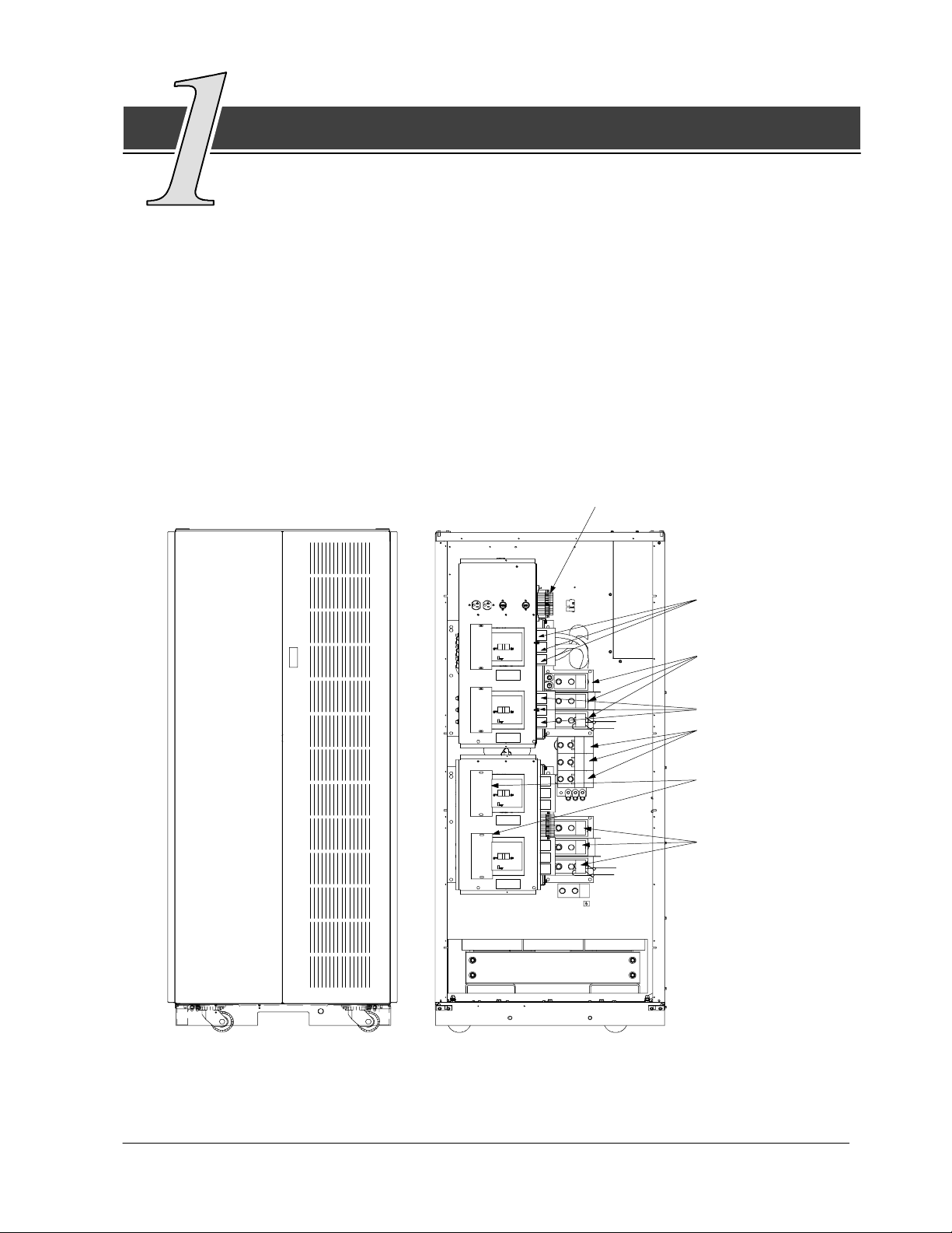
The Powerware 9315 Maintenance Bypass Module (MBM) is a
floor-mounted, enclosed cabinet containing a UPS module, Maintenance
Isolation circuit breaker (MIS), and a maintenance Bypass circuit breakr
(MBP). An optional UPS Module Input Bypass circuit breaker (BIB) is available. The MBM
can be either free-standing or line-up-and-match. Figure 1 shows a typical MBM cabinet
with isolation transformer for a Powerware 9315 30---160kVA UPS and MBM cabinet
without isolation transformer for a Powerware 9315 30 ---160kVA UPS.
The equipment and devices described in this manual are provided for operation with the
specific UPS Modules (model and rating) described in the appendix.
BREAKER ANNUNCIATION
UTILITY INPUT,
IF BIB BREAKER
IS NOT
INSTALLED
MBP
MIS
BIB1
BIB2
CRITICAL LOAD
CONNECTIONS
UPS/PTC OUTPUT
CONNECTION
NEUTRAL
CONNECTIONS
OPTIONAL UPS
BYPASS
INPUT CONNECTIONS
UTILITY INPUT,
IF BIB BREAKER
INSTALLED
Figure 1. Typical 30---160kVA MBM with or without Isolation Transformer.
Powerware 9315 Maintenance Bypass Module 30 --- 160kVA
164201177 Rev. C 041500
1
Page 6

Using This Manual
This manual contains installation and operation procedures for the MBM. Before
installation and operation, read through each procedure.
· Chapter 1 provides an overview of this manual and references for further
information.
· Chapter 2 tells you how to prepare your site for the installation of the MBM.
It discusses equipment environmental requirements, inspecting, and unpacking
cabinets.
· Chapter 3 describes how to install the MBM cabinet.
· Chapter 4 contains operating information for the MBM.
· Appendix A contains important information for planning and installing the MBM,
including wiring data and illustrations of cabinets.
Conventions Used in This Manual
This manual contains installation and operation procedures for the Maintenance
Bypass module.
· Bold type highlights important concepts in discussions, key terms in
procedures, and menu options.
· Italic type highlights notes, references to other system manuals, references
to other sections of this manual, and new terms where they are defined.
· Rectangular boxes containing bold type are warnings or cautions that pertain
to the system or its electrical connections. This important information indicates
possible dangers pertaining to personnel safety, equipment damage, critical
load protection, or operational concerns.
2
Powerware 9315 Maintenance Bypass Module 30-160kVA
164201177 Rev. C 041500
Page 7

For More Information
For more information on the installation and operation of the UPS system and its
accessories, refer to the following:
164200252 Powerware
Each manual describes the UPS cabinet, Control Panel, and
Monitor Panel, and explains the functions of the UPS; discusses
the s tandard features of the UPS and optional accessories;
provides procedures for starting and stopping the UPS, and
information about maintenance and responding to system events.
T h es e a l so de s c r ib e t h e R S --- 4 8 5 a n d RS --- 2 3 2 s e r i a l
communications capabilities of the UPS system; discuss the two
communications ports on the Customer Interface Panel inside the
UPS and how to connect optional remote accessories to your
UPS system; and provide information about enabling, disabling,
and customizing building alarms.
164200253 Powerware
164200292 Powerware
Each manual contains the following information: how to prepare
the site and plan for installation, detailed step-by-step procedures
for installing each component of your system, how to join
cabinets in a line-up-and-match system, detailed illustrations of
cabinets and optional accessories, including dimensions and
connection points.
9315 30--- 160 kVA UPS Operation
9315 30--- 80 kVA UPS Installation
9315 100--- 160 kVA UPS Installation
Contact the local Powerware Field Service office for information on how to obtain
copies of these manuals.
Getting Help
If you have a question about any of the information in this manual, or if you have a
question this manual does not answer, please call Powerware Field Service:
United States 1-800-843-9433
Canada 1-800-461-9166
Outside the U.S. Call your local representative
Powerware 9315 Maintenance Bypass Module 30 --- 160kVA
164201177 Rev. C 041500
3
Page 8

This Page Intentionally Left Blank.
4
Powerware 9315 Maintenance Bypass Module 30-160kVA
164201177 Rev. C 041500
Page 9
Getting Started
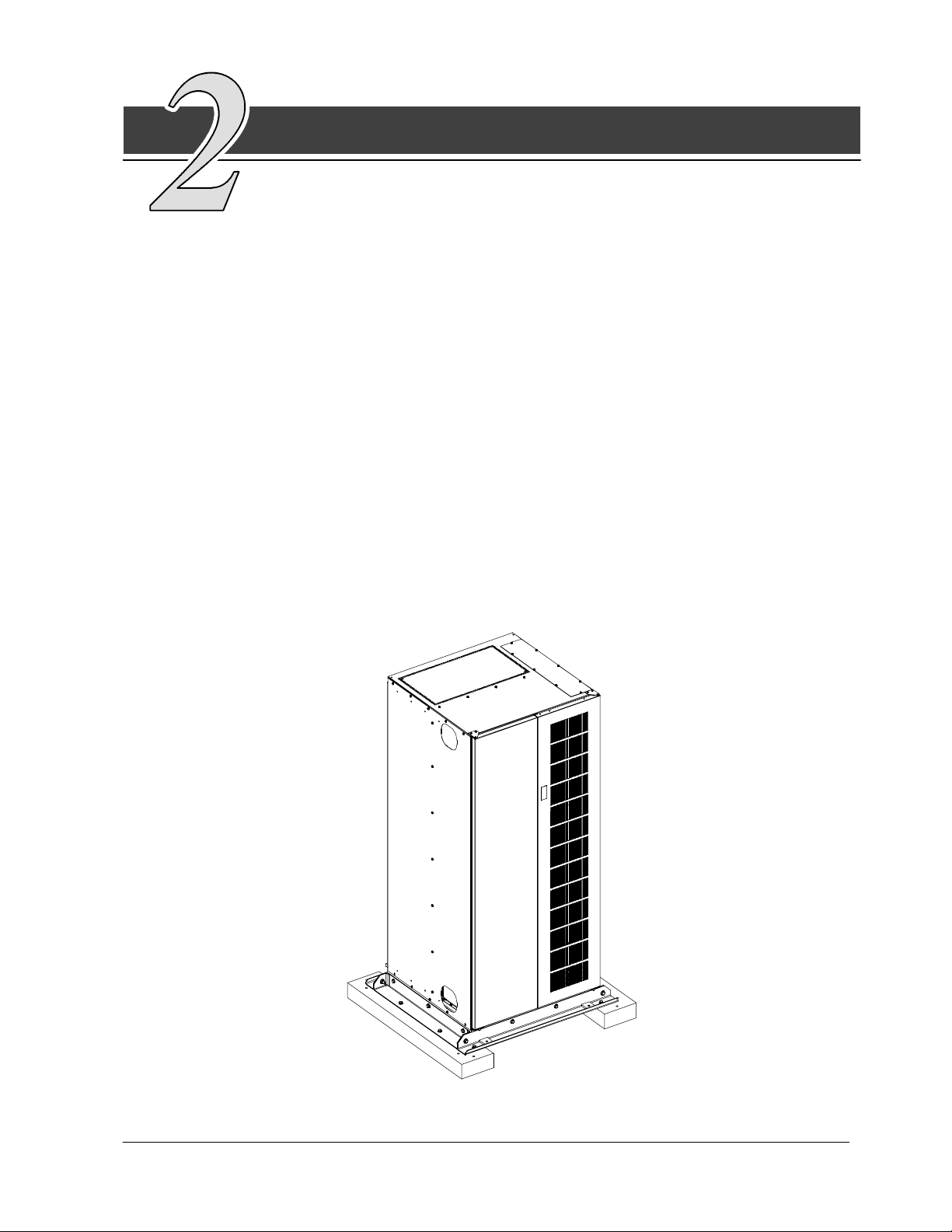
This section describes how to install the Powerware 9315 Maintenance
Bypass Module (MBM). It contains instructions for installing the MBM and
basic site preparation procedures. Figure 2 shows the front and side view of the
MBM with or without transformer for a Powerware 9315 30---160kVA module.
The MBM is shipped as a separate item. Use a forklift or pallet jack to move the
packaged cabinet to the installation site, or as close as possible to the site, before
unloading.
The basic sequence of the installation steps is:
1. Prepare the site for the MBM installation.
2. Inspect, unpack, and unload the MBM.
3. Create an installation plan for wiring the MBM to the UPS system.
4. Prepare for wiring.
5. Complete the installation checklist from the PowerwareR 9315 Installation manual.
6. Have authorized service personnel perform preliminary checks and startup.
NOTE: Startup and operational checks should be performed only by authorized
service personnel. This service is usually offered as part of the sales
contract for your UPS system.
Figure 2. Front and Side View of Typical Maintenance Bypass Module on
Shipping Pallet (30---160kVA with or without XFMR)
Powerware 9315 Maintenance Bypass Module 30 --- 160kVA
164201177 Rev. C 041500
5
Page 10

Preparing the Site
For the MBM to o perate at peak efficiency, the installation site should meet the
environmental parameters outlined in the PowerwareÒ 9315 Operation manual
provided with the UPS system. The operating environment must meet the size and
weight requirements supplied in the PowerwareÒ 9315 Installation manual provided
with the UPS system. If the MBM is to be operated at an altitude higher than 1500
meters (5000 feet), contact the local sales or service office for important information
about high altitude operation.
The basic environmental requirements for operation of the MBM are:
Ambient Temperature Range 0 --- 4 0 ˚C (32 ---104˚F)
Recommended Operating Range 20---25˚C (68--- 77˚F)
Maximum Relative Humidity 95%
The MBM uses convection cooling to regulate internal component temperature. Air
inlets are in the front of the cabinet, and outlets are in the top. Clearance in front of
and above each cabinet for proper air circulation is essential.
Creating an Installation Plan
Before beginning to install the MBM, read and understand how this manual applies
to the system being installed. It is important to note that UPS module installation
procedures are contained in the PowerwareÒ 9315 Installation manual provided
with the UPS system. It is recommended to first understand how to install the UPS
modules. The information in Chapter 2 of this manual is a guide for installation of
the MBM to the UPS modules.
Environmental Considerations
Thelifeofthemaintenancebypassmoduleisadverselyaffectediftheinstallation
does not meet the following guidelines:
1. The MBM must be installed on a sealed concrete pad or floor.
2. The MBM must be installed in a dust-free environment.
3. The MBM must be installed in a humidity-controlled environment.
Preparing for Wiring the Maintenance Bypass Module
See Tables A-1 through A-6 in Appendix A of this manual for wiring requirements.
The power wiring for this equipment is rated at 90_C. Ifwireisruninanambient
temperature greater than 30_C, higher temperature rating and/or larger size wire
may be necessary. Wiring should be installed through the bottom or top entry of
the module. For UPS external wiring requirements, including minimum AWG size
of external wiring, see the PowerwareÒ 9315 Installation manual provided with the
UPS system.
NOTE: Material and labor for external wiring are to be provided by designated
personnel.
6
Powerware 9315 Maintenance Bypass Module 30-160kVA
164201177 Rev. C 041500
Page 11
Inspecting and Unpacking the Maintenance Bypass Module
The first task in preparing for installation of the MBM is inspecting and unpacking
the unit. The MBM arrives covered with protective packaging material as shown in
Figure 3.
OUTER
PACKAG I N G
LAMINATED PLYWOOD
AND POLYFOAM SKIDS
Figure 3. MBM as Shipped, with Outer Packaging and Pallet
Powerware 9315 Maintenance Bypass Module 30 --- 160kVA
164201177 Rev. C 041500
7
Page 12

1. Carefully inspect the outer packaging for evidence of damage during transit.
CAUTION:
Do not install a damaged MBM. Report any damage to the carrier and contact
the local sales or service office immediately.
2. Use a forklift or other material handling equipment to move the MBM to a
convenient unpacking area. Insert the forklift jacks between the laminated
plywood/polyfoam skids on the bottom of the unit.
CAUTION:
Do not tilt unit more than 10 degrees from vertical.
3. Set the pallet on a firm, level surface, allowing a minimum clearance of
4.6m (15 ft) on each side for removing the MBM from the pallet.
4. Cut the steel bands around the MBM.
5. Remove the protective cardboard covering from the MBM, cutting where
indicated, using a knife blade no longer than 25 mm (1 in.).
NOTE: Do not discard the packaging material. Instructions for unloading the MBM
from the pallet are printed on the cardboard. Please to refer to them.
6. Remove the plastic bag and foam packing material. Please discard or recycle
them in a responsible manner.
8
Powerware 9315 Maintenance Bypass Module 30-160kVA
164201177 Rev. C 041500
Page 13

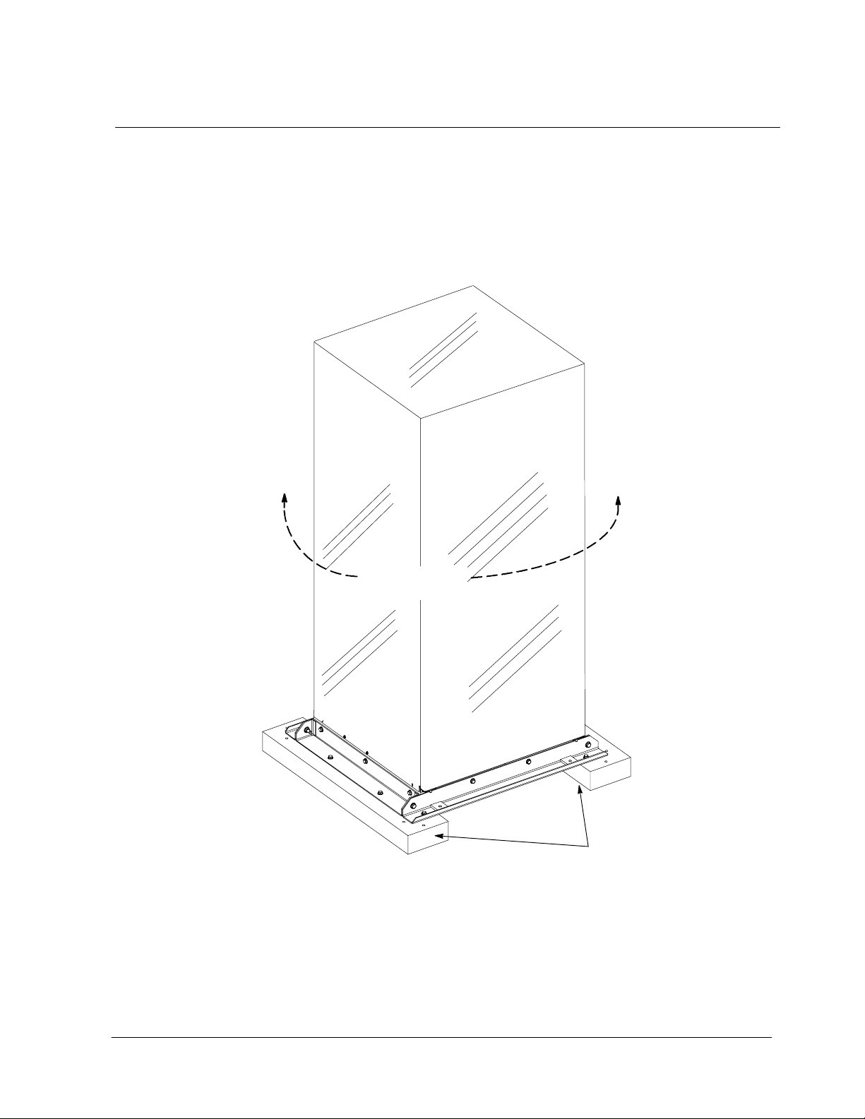
Unloading the MBM from the Pallet
The MBM pallet consists of four metal angle supports secured to plywood /pol y f oam
laminated skids. The skids act as shock absorbers for the MBM during shipment.
WARNING:
Unit is extremely heavy. If unloading instructions are not closely
followed, the unit may tip and cause serious injury.
Turning the jacking bolts unevenly may cause the unit to become
unbalanced. To prevent tipping, raise and lower the jacking bolts
evenly and sequentially. The unit should only be raised approximately
3mm(
1. Remove the doors. Remove the retaining screw located inside each door at
2. Locate the field kit packed inside the unit. Lo cate the four ½-in. jacking bolts
1/8 in.) above the floor (just enough to remove polyfoam skids).
the bottom hinge pivot point, then lift off the door. Save the retaining screws
for reinstallation of the doors.
and install them in the threaded holes in the front and rear supports. Place a
floor protector underneath each jacking bolt, and screw the bolts down until
they contact the floor protectors. The floor protectors prevent the floor from
being damaged by the jacking bolts.
WARNING:
Module may fall. Do not loosen hardware attaching the side or front/rear
shipping supports to the module base. Also, do not loosen the shipping
supports from each other. The module must be lowered using jacking
bolts before the shipping supports can be removed.
3. Loosen, but do not remove the hardware holding the plywood/polyfoam skids
to the front and rear supports (labeled “1” in Figure 4 --- 8 places).
4. Turn each jacking bolt clockwise sequentially, no more than two full turns each,
until the foam cushions clear the floor by approximately 3 mm (
1/8 in.).
5. After the plywood/polyfoam skids clear the floor, remove the hardware
loosened in step 3. Pull the skids out from under the MBM. Discard or recycle
them in a responsible manner.
Powerware 9315 Maintenance Bypass Module 30 --- 160kVA
164201177 Rev. C 041500
9
Page 14
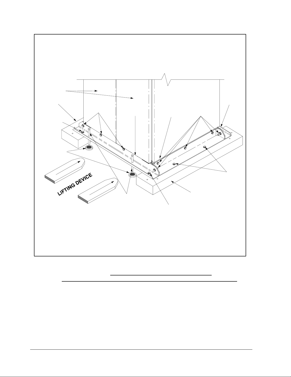
DOOR
POLYFOAM
SKID
1
FLOOR
PROTECTOR
(4 PLACES)
2
(USE FRONT AND REAR)
FRONT SIDE
SUPPORT
JACKING BOLT
SUPPORT
1
REAR
SUPPORT
2
1
POLYFOAM
SKID
10
Figure 4. Detail of Shipping Supports
6. Carefully and evenly lower the MBM by turning each jacking bolt
counterclockwise in sequence no more than two full turns each (maximum)
until the supports contact the floor, and the module is no longer supported by
the jacking bolts.
7. When the module is resting on the floor, remove the jacking bolts. Discard or
recycle them in a responsible manner.
8. Removethehardwarelabeled“2”inFigure4,holdingthefront,rearandside
supports to the module base (14 places). Discard or recycle the hardware and
support brackets in a responsible manner.
9. Install the doors removed in step 1. The MBM is now ready to be rolled to its
final location.
Powerware 9315 Maintenance Bypass Module 30-160kVA
164201177 Rev. C 041500
Page 15
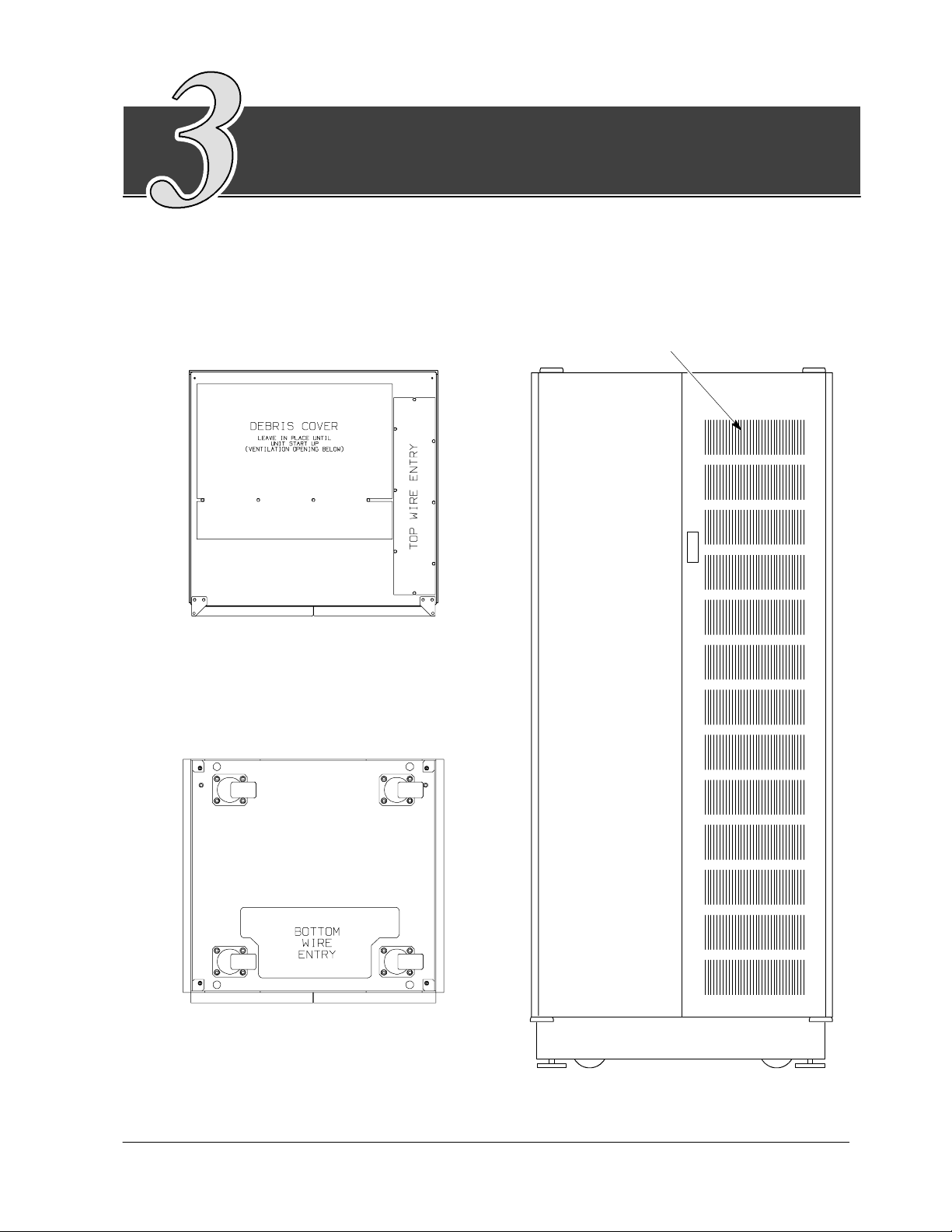
Installing and Wiring the
Maintenance Bypass Module
When the maintenance bypass module (MBM) has been moved to its installed
location, unpacked, and inspected, it is ready for installation. This section
discusses the typical process of installing the MBM in both the line-up and match
and free-standing situations. The MBM is shown in Figure 5.
Cooling Air Inlets
(Front)
Cable Entry, Top Plan View
(Front)
Cable Entry, Bottom Plan View
Figure 5. Top, Bottom, and Front View of Maintenance Bypass Module
(30---160kVA with or without XFMR)
Powerware 9315 Maintenance Bypass Module 30 --- 160kVA
164201177 Rev. C 041500
11
Page 16

Refer to the following while installing the MBM:
· Dimensions in this manual are in millimeters and (inches).
· Do not tilt the unit more than 10˚ during installation.
· Remove the conduit landing plates to add conduit landing holes as required.
Plate material is 16 gauge steel (0.06 in. thick).
· Terminals are UL and CSA rated at 90˚C. A hex key tool is required to attach
wires to the terminals.
· Details about power wiring are provided in the tables of Appendix A of this
manual.
Figure 6 shows typical power wiring terminations of the UPS module and
Maintenance Bypass Module (30--- 160kVA). Refer to the Powerware 9315
Installation manual provided with the UPS system for location of UPS module
cabinet wiring terminations.
NOTE: Material and labor for external wiring are to be provided by designated
personnel.
BREAKER ANNUNCIATION
RIGHT DOOR
UTILITY INPUT,
IF BIB BREAKER
IS NOT
INSTALLED
REMOVED
FOR
CLARITY
MBP
MIS
BIB1
BIB2
Maintenance Bypass Module
Figure 6. Typical Power Wiring Terminations of UPS Module and
CRITICAL LOAD
CONNECTIONS
UPS/PTC OUTPUT
CONNECTION
NEUTRAL
CONNECTIONS
OPTIONAL UPS
BYPASS
INPUT CONNECTIONS
UTILITY INPUT,
IF BIB BREAKER
INSTALLED
LEFT DOOR
A/C Output
E9, E10, E11
TB1
TB2
UPS MODULE
Maintenance Bypass Module (30 ---160kVA)
Output
Neutral
Connection
(E12)
(30--160kVA UPS Shown)
12
Powerware 9315 Maintenance Bypass Module 30-160kVA
164201177 Rev. C 041500
Page 17

The recommended location, for the Maintenance Bypass Module, is as close to the
installed UPS module as possible. Refer to the tables in Appendix A for wire rating
and sizing information
The MBM is packaged in a module similar to the UPS modules (same height,
width, depth). The MBM is designed as a standard line-up-and-match accessory
for the 30---160 KVA rated modules.
Wiring harness assemblies for connecting the UPS module bypass input and
output to the MBP are provided in separate shipping containers, if applicable. The
wiring harness assemblies are passed through the 3-inch wiring feed-through hole
located at the lower right side of the MBM cabinet, for connecting to the UPS input
and output terminals. Refer to Appendix A for UPS module to MBM wiring terminal
locations.
Line up and match connection (cables sold separately by Powerware)
· From the UPS to the MBM, the power cables are connected by mechanical
pressure lugs.
· From the UPS to the MBM, the control cables are connected to terminal blocks.
Remote connection (cables, lugs, and hardware supplied by others)
· All cables are terminated to MBM mechanical pressure lugs.
LineandLoadWiring
The Maintenance Bypass Module provides a means to manually transfer the Critical
load from the UPS module via the UPS Module Bypass to a Maintenance Bypass
Module as may be necessary for shutting down the UPS Module for maintenance
or testing. The proper operation of the transfer is accomplished without interrupting
the load power.
The UPS Module Bypass AC Input and the Maintenance Bypass AC Input must be
from the same or synchronized AC sources. The UPS Module Bypass Input is
connected through the MBP cabinet via an optional Bypass Input Breaker (BIB), if
installed. The Maintenance Bypass Breaker (MBP) is placed in the secondary of the
stepdown transformer (480:208 VAC or 600:208 VAC) or connected directly to the
Maintenance Bypass source if the Isolation Transformer is not required.
UPS Module AC output connects through the MBM cabinet via isolation breaker
MIS. Critical L oad terminals are located on the load side of breakers MBP and MIS.
The Critical Load may be transferred in a Make-Before-Break transfer sequence
between the UPS Bypass Source and the Maintenance Bypass source after UPS
output has been transferred from the UPS module and UPS bypass operating
mode. The MBP must first be closed to prevent power interruption and MIS opened
to provide UPS isolation from the Critical Load bus. Refer to the Transfer Sequence
placard affixed to the front of the MBM cabinet.
Powerware 9315 Maintenance Bypass Module 30 --- 160kVA
164201177 Rev. C 041500
13
Page 18

This Page Intentionally Left Blank.
14
Powerware 9315 Maintenance Bypass Module 30-160kVA
164201177 Rev. C 041500
Page 19

Maintenance Bypass Module Operation
This chapter provides preliminary checks, maintenance operations and a
schematic diagram of the maintenance bypass module.
Preliminary Checks and Startup for UPS Equipped with
Maintenance Bypass Module (MBM)
Installation inspection and startup procedures must be performed only by a
Powerware Corporation authorized service person. The procedure is normally part
of the sales contract for the UPS system.
WARNING:
Attempts to startup the UPS system yourself may damage equipment and/or
your critical load. Such attempts may also invalidate your system warranty.
Maintenance Bypass Module Operation
The MBM is provided for use with the Powerware 9315 (30 ---160kVA) UPS module.
WARNING:
Only persons familiar with the operation of this equipment should transfer loads.
Failure to follow the transfer sequence exactly may cause loss of power to the
critical load or may cause overload protection devices to function.
Operator Note:
MIS is to be OPENED only after MBP is CLOSED
MBP is to be OPENED only after MIS is CLOSED
Powerware 9315 Maintenance Bypass Module 30 --- 160kVA
164201177 Rev. C 041500
15
Page 20

MBM Operation Without Kirk Key Interlocks
The following transfer sequence is the recommended procedure for the
step-by-step load transfer from and back to the UPS when required. This
information is provided on a label located on the deadfront panel behind
the right front door of the MBM.
From UPS Bypass to Maintenance Bypass:
1. Confirm BIBs, if installed, are closed.
2. Transfer UPS from Normal to Bypass mode (see UPS Operation manual).
NOTE: For Parallel Redundant systems, transfer both UPS modules to
Bypass mode.
3. Close MBP breaker.
CAUTION:
Failure to close MBP breaker results in loss of power to the critical load.
4. Open MIS breaker.
5. Deenergize UPS before servicing unit (see UPS operation manual).
CAUTION:
For UPS electrical isolation, BIB breaker (if applicable) must be opened.
From Maintenance Bypass to UPS Bypass:
1. Confirm BIBs, if installed, are closed.
2. Transfer UPS from Normal to Bypass mode (see UPS Operation manual).
NOTE: For Parallel Redundant systems, transfer both UPS modules to
Bypass mode.
3. Close MIS breaker.
CAUTION:
Failure to close MIS breaker results in loss of power to the critical load.
4. Open MBP breaker.
5. To place UPS in Normal Mode, see UPS operation manual.
NOTE: While the UPS is in Normal Mode and the MIS breaker is closed, the MBP
breaker always trips OFF. Likewise, while the UPS is in Normal Mode and the
MBP is closed, the MIS breaker always trips OFF.
16
Powerware 9315 Maintenance Bypass Module 30-160kVA
164201177 Rev. C 041500
Page 21

MBM Operation With Kirk Key Interlocks (Optional)
The following transfer sequence is the recommended procedure for the
step-by-step load transfer from and back to the UPS when required. This
information is provided on a label located on the deadfront panel behind
the right front door of the MBM.
Kirk Key Solenoid Release Unit (SKRU)
The 120 VAC operating power for the Kirk Key Solenoid Release Unit (SKRU) is
derived from the Maintenance Bypass source.
The Kirk Key SKRU is provided to prevent access to the key, which is necessary to
initiate the transfer sequence. The operator must observe the instructions on the
Transfer Sequence nameplate mounted on the MBP Panelboard.
Electrical interlocks inhibit key release until UPS is in the Bypass mode.
MBM Transfer Sequences
From UPS Bypass to Maintenance Bypass:
1. Confirm BIBs, if installed, are closed.
2. Transfer UPS from Normal to Bypass mode (see UPS Operation manual).
NOTE: For Parallel Redundant systems, transfer both UPS modules to
Bypass mode.
3. Depress pushbutton on the solenoid key release unit (SKRU). Turn and
remove key “A”. Key “A” may be removed when UPS system is in Bypass
mode as indicated by illuminated pilot light.
4. Insert key “A” into MBP lock, retract bolt, close MBP breaker. Remove key “B”.
CAUTION:
Failure to close MBP breaker results in loss of power to the critical load.
5. Insert key “B’ into MIS lock, open MIS breaker, extend bolt. Remove key “A”.
6. Insert key “A” into solenoid and turn key to LOCK position.
7. Deenergize UPS before servicing (see UPS Operation manual).
CAUTION:
For UPS electrical isolation, BIB breaker (if applicable) must be opened.
Powerware 9315 Maintenance Bypass Module 30 --- 160kVA
164201177 Rev. C 041500
17
Page 22

From Maintenance Bypass to UPS Bypass:
1. Confirm BIBs, if installed, are closed.
2. Transfer UPS to Bypass mode (see UPS Operation manual).
NOTE: For Parallel Redundant systems, transfer both UPS modules to
Bypass mode.
3. Depress pushbutton on the Solenoid Key Release Unit (SKRU). Turn and
remove key “A”.
4. Insert key “A” into MIS lock, retract bolt, close MIS breaker. Remove key “B”.
CAUTION:
Failure to close MBP breaker results in loss of power to the critical load.
5. Insert key “B” into MBP lock, open MBP breaker, extend bolt. Remove key “A”.
6. Insert key “A” into solenoid and turn key to LOCK position.
7. SeeUPSOperationmanualtoplaceUPSinNormalmode.
WARNING:
Dangerous and potentially lethal voltages are present within the UPS enclosure.
When maintenance or repair activities are to be performed, the UPS and the UPS
Bypass power sources should be deenergized and verified with a meter before
working in the required area.
WARNING:
UPS equipment has power feeds that are derived from two or more power
sources.
18
Powerware 9315 Maintenance Bypass Module 30-160kVA
164201177 Rev. C 041500
Page 23

Maintenance
Maintenance should be scheduled on a periodic basis, recommended not to
exceed one year. More frequent intervals are recommended if the equipment is
subjected to highly repetitive operations.
CAUTION:
Refer to Section 9 -- Maintaining the UPS System of the Powerware 9315
30--160kVA Operation manual, Powerware part number 164200252, before
beginning maintenance or repairs on the UPS equipment.
WARNING:
Dangerous and life-threatening voltages are present when the UPS is
operating. De-energize all equipment before physically touching potentially
live parts.
Periodic inspections of the maintenance bypass module should be made to
determine if components, wiring, and connections exhibit evidence of overheating.
Particular attention should be given to bolted connections. Maintenance
procedures should specify that the bolted connections be retorqued to values
listed on labels posted on the equipment.
CAUTION:
Overtightening of bolted connections containing compression washers
decreases the washer’s ability to maintain compression during heating and
cooling cycles.
Refer to circuit breaker manufacturer’s application and maintenance literature for
recommended maintenance practices and procedures.
Short Circuits
Short circuits are not considered normal phenomena in UPS applications. Tripping
of protective devices due to low impedance short circuits should be thoroughly
investigated for damage to conductors, insulation, and the protective devices in
accordance with the manufacturer’s recommendations.
Maintenance Bypass Module Diagrams
See Appendix A for onelines and system configuration schematics
Powerware 9315 Maintenance Bypass Module 30 --- 160kVA
164201177 Rev. C 041500
19
Page 24

This Page Intentionally Left Blank.
20
Powerware 9315 Maintenance Bypass Module 30-160kVA
164201177 Rev. C 041500
Page 25

Appendix A --- Customer Information
The information in this appendix will help you plan for and install your Maintenance Bypass
Module cabinet. This appendix contains the following:
· 164201177 ---1 Installation Notes
· 164201177 ---2 Typical MBM Cabinet --- 30-160kVA with or without XFMR
· 164201177 ---3 Typical UPS System with MBM
· 164201177 ---4 Oneline --- 30-160kVA, Reverse Transfer (RT), 480:480VAC,
600:600VAC, 400:400VAC
· 164201177 ---5 Oneline --- 30-160kVA, Reverse Transfer (RT), 480:208VAC,
600:208VAC
· 164201177 ---6 Oneline --- 30-160kVA, Reverse Transfer (RT), 208:208VAC,
· 164201177 ---7 Oneline --- 30-160kVA, Parallel, 480:480VAC, 600:600VAC,
400:400VAC
· 164201177 ---8 Oneline --- 30-160kVA, Parallel, 480:208VAC, 600:208VAC
· 164201177 ---9 Oneline --- 30-160kVA, Parallel, 208:208VAC
· 164201177 ---10 UPS Module Line Up and Match 1 through 3
Powerware 9315 Maintenance Bypass Module 30 --- 160kVA
164201177 Rev. C 041500
A --- 1
Page 26

Table A -- 1. Ratings & External Wiring Requirements for Powerware 9315
A
B
C
D
A
B
C
D
M B M 3 0 --- 1 6 0
Rating and External Wiring Requirement
Basic unit rating at
0.8 lagging PF load
UPS Input Voltage/Bypass Input
UPS Output Voltage
AC Input to Maintenance Bypass
(3) Phases, (1) Ground
Conductor Size
Number per Phase
AC Input to UPS Bypass
(3) Phases, (1) Ground
Conductor Size
Number per Phase
AC Output to Critical Load
(3) Phases, (1) Neutral, (1) Ground
Conductor Size
Number per Phase
UPS/PTC Output to MBM Cabinet (MIS)
(3) Phases, (1) Neutral, (1) Ground
Conductor Size
Number per Phase
E
Control Wiring to UPS
(2) Conductors
kVA, 480:208VAC/600:208VAC
Units Rating 60 Hz
KVA
KW
VOLTS
VOLTS
AMPS 192 153 156 125 120 96 96 77
AWG/MCM
(each)
AMPS 192 153 156 125 120 96 96 77
AWG/MCM
(each)
AMPS 444 444 361 361 278 278 222 222
AWG/MCM
(each)
AMPS 444 444 361 361 278 278 222 222
AWG/MCM
(each)
VOLTS
AMPS
160
128
480
600
208
208
300
300
(1)
(1)
300
300
(1)
(1)
400
400
(2)
(2)
400
400
(2)
(2)
1201120112011201120112011201120
480
208
300
(1)
300
(1)
400
(2)
400
(2)
130
104
600
208
300
(1)
300
(1)
400
(2)
400
(2)
408
208
300
(1)
300
(1)
400
(2)
400
(2)
100
80
600
208
300
(1)1(1)1(1)
300
(1)1(1)1(1)
400
(2)
400
(2)
80
64
480
208
300
(1)
300
(1)
600
208
300
(1)
300
(1)
1
Basic unit rating at
0.8 lagging PF load
UPS Input Voltage/Bypass Input
UPS Output Voltage
AC Input to Maintenance Bypass
(3) Phases, (1) Ground
Conductor Size
Number per Phase
AC Input to UPS Bypass
(3) Phases, (1) Ground
Conductor Size
Number per Phase
AC Output to Critical Load
(3) Phases, (1) Neutral, (1) Ground
Conductor Size
Number per Phase
UPS/PTC Output to MBM Cabinet (MIS)
(3) Phases, (1) Neutral, (1) Ground
Conductor Size
Number per Phase
E
Note: Callout letters A, B, C, D,and E map to drawing 164201177 ---5 (Reverse Transfer Connection) and
Control Wiring to UPS
(2) Conductors
164201177---8 (Parallel Connection). Read and understand the notes on drawings when planning your installation.
KVA
KW
VOLTS
VOLTS
AMPS 78 63 60 48 48 38 36 29
AWG/MCM
(each)
AMPS 78 63 60 48 48 38 36 29
AWG/MCM
(each)
AMPS 180 180 139 139 111 111 83 83
AWG/MCM
(each)
AMPS 180 180 139 139 111 111 83 83
AWG/MCM
(each)
VOLTS
AMPS
65
52
480
600
208
208
1
(1)1(1)
1
(1)1(1)
300
300
(1)
(1)
300
300
(1)
(1)
1201120112011201120112011201120
50
40
480
208
1
(1)1(1)
1
(1)1(1)
300
(1)
300
(1)
600
208
300
(1)
300
(1)
480
208
1
(1)
1
(1)
300
(1)
300
(1)
40
32
600
208
1
(1)1(1)1(1)
1
(1)1(1)1(1)
300
(1)
300
(1)
480
208
300
(1)
300
(1)
30
24
600
208
300
(1)
300
(1)
1
A --- 2
DESCRIPTION:
DRAWING NO:
REVISION:
INSTALLATION NOTES
164201177--- 1
C
DATE:
SHEET:
041500
Powerware 9315 Maintenance Bypass Module 30-160kVA
164201177 Rev. C 041500
1of4
Page 27

Table A -- 2. Ratings & External Wiring Requirements for Powereware 9315
A
B
C
D
A
B
C
D
M B M 3 0 --- 1 6 0
Rating and External Wiring Requirement
Basic unit rating at
0.8 lagging PF load
UPS Input Voltage/Bypass Input
UPS Output Voltage
AC Input to Maintenance Bypass
(3) Phases, (1) Ground
Conductor Size
Number per Phase
AC Input to UPS Bypass
(3) Phases, (1) Ground
Conductor Size
Number per Phase
AC Output to Critical Load
(3) Phases, (1) Neutral, (1) Ground
Conductor Size
Number per Phase
UPS/PTC Output to MBM Cabinet (MIS)
(3) Phases, (1) Neutral, (1) Ground
Conductor Size
Number per Phase
E
Control Wiring to UPS
(2) Conductors
kVA, 480:480VAC/600:600VAC
Units Rating 60 Hz
KVA
KW
VOLTS
VOLTS
AMPS 192 153 156 125 120 96
AWG/MCM
(each)
AMPS 192 153 156 125 120 96
AWG/MCM
(each)
AMPS 192 153 156 125 120 96
AWG/MCM
(each)
AMPS 192 153 156 125 120 96
AWG/MCM
(each)
VOLTS
AMPS
160
128
480
600
480
600
300
300
(1)
300
(1)
300
(1)
300
(1)
12011201120112011201120
(1)
300
(1)
300
(1)
300
(1)
480
480
300
(1)
300
(1)
300
(1)
300
(1)
130
104
600
600
300
(1)
300
(1)
300
(1)
300
(1)
100
80
480
480
300
(1)
300
(1)
300
(1)
300
(1)
600
600
300
(1)
300
(1)
300
(1)
300
(1)
1
Basic unit rating at
0.8 lagging PF load
UPS Input Voltage/Bypass Input
UPS Output Voltage
AC Input to Maintenance Bypass
(3) Phases, (1) Ground
Conductor Size
Number per Phase
AC Input to UPS Bypass
(3) Phases, (1) Ground
Conductor Size
Number per Phase
AC Output to Critical Load
(3) Phases, (1) Neutral, (1) Ground
Conductor Size
Number per Phase
UPS/PTC Output to MBM Cabinet (MIS)
(3) Phases, (1) Neutral, (1) Ground
Conductor Size
Number per Phase
E
Note: Callout letters A, B, C, D,and E Map to drawing 164201177 ---4 (Reverse Transfer Connection) and
Control Wiring to UPS
(2) Conductors
164201177---7 (Parallel Connection). Read and understand the notes on drawings when planning your installation.
KVA
806465525040403230
KW
VOLTS
VOLTS
AMPS 96 78 60 48 36
AWG/MCM
(each)
AMPS 96 78 60 48 36
AWG/MCM
(each)
AMPS 96 78 60 48 36
AWG/MCM
(each)
AMPS 96 78 60 48 36
AWG/MCM
(each)
VOLTS
AMPS
480
480
1201120112011201120
(1)
(1)
(1)
(1)
480
480
480
1
(1)
1
(1)
1
(1)
1
(1)
480
480
1
(1)1(1)
1
(1)1(1)
1
(1)1(1)
1
(1)1(1)
480
1
1
1
1
1
(1)
1
(1)
1
(1)
1
(1)
24
480
480
1
Powerware 9315 Maintenance Bypass Module 30 --- 160kVA
164201177 Rev. C 041500
DESCRIPTION:
DRAWING NO:
REVISION:
INSTALLATION NOTES
164201177--- 1
C
DATE:
SHEET:
041500
2of4
A --- 3
Page 28

Table A -- 3. Ratings & External Wiring Requirements for Powerware 9315
A
B
C
D
M B M 3 0 --- 1 6 0
Rating and External Wiring Requirement
Basic unit rating at
0.8 lagging PF load
UPS Input Voltage/Bypass Input
UPS Output Voltage
AC Input to Maintenance Bypass
(3) Phases, (1) Neutral, (1) Ground
Conductor Size
Number per Phase
AC Input to UPS Bypass
(3) Phases, (1) Ground
Conductor Size
Number per Phase
AC Output to Critical Load
(3) Phases, (1) Neutral, (1) Ground
Conductor Size
Number per Phase
UPS/PTC Output to MBM Cabinet (MIS)
(3) Phases, (1) Neutral, (1) Ground
Conductor Size
Number per Phase
E
Control Wiring to UPS
(2) Conductors
kVA, 208:208VAC
Units Rating 60 Hz
KVA
KW
VOLTS
VOLTS
AMPS 444 361 278 222 180 139 111 83
AWG/MCM
(each)
AMPS 444 361 278 222 180 139 111 83
AWG/MCM
(each)
AMPS 444 361 278 222 180 139 111 83
AWG/MCM
(each)
AMPS 444 361 278 222 180 139 111 83
AWG/MCM
(each)
VOLTS
AMPS
160
128
130
10080806465525040403230
104
208
208
400
400
400
400
1201120112011201120112011201120
(2)
(2)
(2)
(2)
208
208
400
(2)
400
(2)
400
(2)
400
(2)
208
208
400
(2)
400
(2)
400
(2)
400
(2)
208
208
300
(1)
300
(1)
300
(1)
300
(1)
208
208
300
(1)
300
(1)
300
(1)
300
(1)
208
208
300
(1)
300
(1)
300
(1)
300
(1)
208
208
300
(1)
300
(1)
300
(1)
300
(1)
24
208
208
300
(1)
300
(1)
300
(1)
300
(1)
1
Note: Callout letters A, B, C, D,and E map to drawing 164201177 ---6 (Reverse Transfer Connection) and
164201177---9 (Parallel Connection). Read and understand the notes on drawings when planning your installation.
A --- 4
DESCRIPTION:
DRAWING NO:
REVISION:
INSTALLATION NOTES
164201177--- 1
C
DATE:
SHEET:
041500
Powerware 9315 Maintenance Bypass Module 30-160kVA
164201177 Rev. C 041500
3of4
Page 29

Table A--4. Rating and External Wiring Requirements for Powerware 9315
A
B
C
D
M B M 5 0 --- 1 6 0
RATING AND EXTERNAL WIRING REQUIREMENT UNITS RATING 50/60 HZ
BASIC UNIT RATING AT
0.8 LAGGING PF LOAD
UPS INPUT VOLTAGE
BYPASS INPUT/UPS OUTPUT VOL T AGE
AC INPUT TO MAINTENANCE BYPASS
(3) PHASES, (1) GROUND
CONDUCTOR SIZE
NUMBER PER PHASE
AC INPUT TO UPS BYPASS
(3) PHASES, (1) GROUND
CONDUCTOR SIZE
NUMBER PER PHASE
AC OUTPUT TO CRITICAL LOAD
(3) PHASES, (1) NEUTRAL, (1) GROUND
CONDUCTOR SIZE
NUMBER PER PHASE
UPS/PTC OUTPUT TO MBM CABINET (MIS)
(3) PHASE, (1) NEUTRAL, (1) GROUND
CONDUCTOR SIZE
NUMBER PER PHASE
CONTROL WIRING TO UPS
E
(2) CONDUCTORS
KVA, 380:380VAC, 400:400VAC, 415:415VAC
KVA
KW
VOLTS
VOLTS
AMPS 231 188 146 115 97 74 60 45
AWG/MCM
(each)
AMPS 231 188 146 115 97 74 60 45
AWG/MCM
(each)
AMPS 231 188 146 115 97 74 60 45
AWG/MCM
(each)
AMPS 231 188 146 115 97 74 60 45
AWG/MCM
(each)
VOLTS
AMPS
160
130
128
300
(1)
300
(1)
300
(1)
300
(1)
1201120112011201120112011201120
10080806465
104
300
300
(1)
(1)
300
300
(1)
(1)
300
300
(1)
(1)
300
300
(1)
(1)
52
380/400/415
380/400/415
300
300
(1)
(1)1(1)1(1)
300
300
(1)
(1)1(1)1(1)
300
300
(1)
(1)1(1)1(1)
300
300
(1)
(1)1(1)1(1)
50
40
40
32
30
24
1
(1)
1
(1)
1
(1)
1
(1)
1
Note: Callout letters A, B, C, D,and E map to drawing 164201177 --- 4 (Reverse Transfer Connection) and
164201177---7 (Parallel Connection). Read and understand the notes on drawings when planning your installation.
DESCRIPTION:
DRAWING NO:
REVISION:
INSTALLATION NOTES
164201177--- 1
C
DATE:
041500
SHEET:
4of4
Powerware 9315 Maintenance Bypass Module 30 --- 160kVA
164201177 Rev. C 041500
A --- 5
Page 30

MBM
FAMIL Y
MBM
30KVA
0KV
A
0KV
A
MBM 50
40KVA
5
MBM 80
5
65KVA
Table B. Circuit Breaker Requirements for Powerware 9315
M B M 3 0 --- 1 6 0
Model No.
MBM 50/30 --- 48/20 480V/208V 36A/83A 100A/40A 150 --- 1200A 250A/100A 375 ---3000A
MBM 50/30 --- 48/48 480V/480V 36A/36A 100A/40A 150 --- 1200A 100A/40A 150---1200A
MBM 50/30 --- 60/20 600V/208V 29A/83A 100A/40A 150 --- 1200A 250A/100A 375 ---3000A
MBM 50/30 --- 20/20 208V/208V 83A/83A 250A/100A 375--- 3000A 250A/100A 375 ---3000A
MBM 50/30 --- 38/38 380V/380V 45A/45A 100A/50A 150 --- 1200A 100A/50A 150---1200A
MBM 50/30 --- 40/40 400V/400V 45A/45A 100A/50A 150 --- 1200A 100A/50A 150---1200A
MBM 50/30 --- 41/41 410V/410V 45A/45A 100A/50A 150 --- 1200A 100A/50A 150---1200A
MBM 50/40 --- 48/20 480V/208V 48A/111A 100A/50A 150---1200A 250A/125A 375--- 3000A
MBM 50/40 --- 48/48 480V/480V 48A/48A 100A/50A 150 --- 1200A 100A/50A 150---1200A
MBM 50/40 --- 60/20 600V/208V 38A/111A 100A/40A 150---1200A 250A/125A 375--- 3000A
MBM 50/40 --- 20/20 208V/208V 111A/111A 250A/125A 375---3000A 250A/125A 375--- 3000A
MBM 50/40 --- 38/38 380V/380V 60A/60A 100A/70A 150 --- 1200A 100A/70A 150---1200A
MBM 50/40 --- 40/40 400V/400V 60A/60A 100A/70A 150 --- 1200A 100A/70A 150---1200A
MBM 50/40 --- 41/41 415V/415V 60A/60A 100A/70A 150 --- 1200A 100A/70A 150---1200A
MBM 50/50 --- 48/20 480V/208V 60A/139A 100A/70A 150---1200A 250A/150A 375--- 3000A
MBM 50/50 --- 48/48 480V/480V 60A/60A 100A/70A 150 --- 1200A 100A/70A 150---1200A
MBM 50/50 --- 60/20 600V/208V 48A/139A 100A/50A 150---1200A 250A/150A 375--- 3000A
MBM 50/50 --- 20/20 208V/208V 139A/139A 250A/150A 375---3000A 250A/150A 375--- 3000A
MBM 80/50 --- 48/20 480V/208V 60A/139A 100A/70A 150---1200A 250A/150A 375--- 3000A
MBM 80/50 --- 48/48 480V/480V 60A/60A 100A/70A 150 --- 1200A 100A/70A 150---1200A
MBM 80/50 --- 60/20 600V/208V 48A/139A 100A/50A 150---1200A 250A/150A 375--- 3000A
MBM 80/50 --- 38/38 380V/380V 74A/74A 100A/80A 150 --- 1200A 100A/80A 150---1200A
MBM 80/50 --- 40/40 400V/400V 74A/74A 100A/80A 150 --- 1200A 100A/80A 150---1200A
MBM 80/50 --- 41/41 415V/415V 74A/74A 100A/80A 150 --- 1200A 100A/80A 150---1200A
MBM 80/50 --- 20/20 208V/208V 139A/139A 250A/150A 375---3000A 250A/150A 375--- 3000A
MBM 80/65 --- 48/20 480V/208V 78A/180A 100A/80A 150---1200A 250A/200A 375--- 3000A
MBM 80/65 --- 48/48 480V/480V 78A/78A 100A/80A 150 --- 1200A 100A/80A 150---1200A
MBM 80/65 --- 60/20 600V/208V 63A/180A 100A/70A 150---1200A 250A/200A 375--- 3000A
MBM 80/65 --- 38/38 380V/380V 97A/97A 250A/100A 375--- 3000A 250A/100A 375 ---3000A
MBM 80/65 --- 40/40 400V/400V 97A/97A 250A/100A 375--- 3000A 250A/100A 375 ---3000A
MBM 80/65 --- 41/41 415V/415V 94A/94A 250A/100A 375--- 3000A 250A/100A 375 ---3000A
MBM 80/65 --- 20/20 208V/208V 180A/180A 250A/200A 375---3000A 250A/200A 375--- 3000A
KVA, 380:380VAC, 400:400VAC, 415:415VAC, 600:600VAC,
480:208
VAC, 600:208VAC, 208:208VAC, 480:480VAC.
BIB1 & BIB2 MBP & MIS
Vin/V
out
Iin/I
out
Frame/T rip
Instantaneous
Trip Ra n ge
Frame/T rip
Instantaneous
Trip Ra n ge
NOTE: See Sheet 2 For Model Number Legend.
DESCRIPTION:
DRAWING NO:
REVISION:
A --- 6
INSTALLATION NOTES
164201177--- 1
C
DATE:
041500
SHEET:
Powerware 9315 Maintenance Bypass Module 30-160kVA
1of2
164201177 Rev. C 041500
Page 31

MBM
FAMIL Y
MBM
80KVA
100KV
A
130KV
A
160KV
A
MBM 80
MBM 160
Table B. Circuit Breaker Requirements for Powerware 9315
M B M 3 0 --- 1 6 0 KVA, 380:380VAC, 400:400VAC, 415:415VAC, 600:600VAC,
480:208VAC, 600:208VAC, 208:208VAC, 480:480VAC.
BIB1 & BIB2 MBP & MIS
Vin/V
Model No.
MBM 80/50 --- 48/20 480V/208V 60A/139A 100A/70A 150--- 1200A 250A/150A 375 ---3000A
MBM 80/80 --- 48/20 480V/208V 96A/222A 100A/100A 150--- 1200A 250A/237A 375 --- 3000A
MBM 80/80 --- 48/48 480V/480V 96A/96A 100A/100A 150---1200A 100A/100A 150--- 1200A
MBM 80/80 --- 60/20 600V/208V 77A/222A 100A/80A 150--- 1200A 250A/237A 375 ---3000A
MBM 80/80 --- 38/38 380V/380V 115A/115A 250A/125A 375--- 3000A 250A/125A 375---3000A
MBM 80/80 --- 40/40 400V/400V 115A/115A 250A/125A 375--- 3000A 250A/125A 375---3000A
MBM 80/80 --- 41/41 415V/415V 115A/115A 250A/125A 375--- 3000A 250A/125A 375---3000A
MBM 80/80 --- 20/20 208V/208V 222A/222A 250A/237A 375--- 3000A 250A/237A 375---3000A
MBM 160/100 --- 48/20 480V/208V 120A/278A 250A/125A 375--- 3000A 600A/300A 900 ---7200A
MBM 160/100 --- 48/48 480V/480V 120A/120A 250A/125A 375--- 3000A 250A/125A 375 ---3000A
MBM 160/100 --- 60/20 600V/208V 96A/278A 250A/100A 375--- 3000A 600A/300A 900 --- 7200A
MBM 160/100 --- 60/60 600V/600V 96A/96A 250A/100A 375 ---3000A 250A/100A 375---3000A
MBM 160/100 --- 38/38 380V/380V 146A/146A 250A/150A 375--- 3000A 250A/150A 375 ---3000A
MBM 160/100 --- 40/40 400V/400A 146A/146A 250A/150A 375 --- 3000A 250A/150A 375 ---3000A
MBM 160/100 --- 41/41 415V/415V 146A/146A 250A/150A 375--- 3000A 250A/150A 375 ---3000A
MBM 160/100 --- 20/20 208V/208A 278A/278A 600A/300A 900 --- 7200A 600A/300A 900 ---7200A
MBM 160/130 --- 48/20 480V/208V 156A/361A 250A/175A 375--- 3000A 600A/420A 900 ---7200A
MBM 160/130 --- 48/48 480V/480V 156A/156A 250A/175A 375--- 3000A 250A/175A 375 ---3000A
MBM 160/130 --- 60/20 600V/208V 125A/361A 250A/150A 375--- 3000A 600A/420A 900 ---7200A
MBM 160/130 --- 60/60 600V/600V 125A/125A 250A/150A 375--- 3000A 250A/150A 375 ---3000A
MBM 160/130 --- 38/38 380V/380V 188A/188A 250A/200A 375--- 3000A 250A/200A 375 ---3000A
MBM 160/130 --- 40/40 400V/400V 188A/188A 250A/200A 375--- 3000A 250A/200A 375 ---3000A
MBM 160/130 --- 41/41 415V/415V 188A/188A 250A/200A 375--- 3000A 250A/200A 375 ---3000A
MBM 160/130 --- 20/20 208V/208V 361A/361A 600A/420A 900--- 7200A 600A/420A 900 ---7200A
MBM 160/160 --- 48/20 480V/208V 192A/444A 250A/200A 375--- 3000A 600A/480A 900 ---7200A
MBM 160/160 --- 48/48 480V/480V 192A/192A 250A/200A 375--- 3000A 250A/200A 375 ---3000A
MBM 160/160 --- 60/20 600V/208V 153A/444A 250A/175A 375--- 3000A 600A/480A 900 ---7200A
MBM 160/160 --- 60/60 600V/600V 153A/153A 250A/175A 375--- 3000A 250A/175A 375 ---3000A
MBM 160/160 --- 38/38 380V/380V 231A/231A 250A/237A 375--- 3000A 250A/237A 375 ---3000A
MBM 160/160 --- 40/40 400V/400V 231A/231A 250A/237A 375--- 3000A 250A/237A 375 ---3000A
MBM 160/160 --- 41/41 415V/415V 231A/231A 250A/237A 375--- 3000A 250A/237A 375 ---3000A
MBM 160/160 --- 20/20 208V/208V 444A/444A 600A/480A 600A/480A 900--- 7200A
out
Iin/I
out
Frame/T rip
Instantaneous
Trip Ra n ge
Frame/T rip
Instantaneous
Trip Ra n ge
NOTE: Model Number Legend
1. MBM 50/30---20/20 means MBM cabinet,
Family 50, 208V (input) and 208V (output),
model 30 (30kVA).
2. All breakers are 100% UL rated with
Interrupting Capacity (IC) of 65kAIC@480VAC.
Powerware 9315 Maintenance Bypass Module 30 --- 160kVA
DESCRIPTION:
DRAWING NO:
REVISION:
INSTALLATION NOTES
164201177--- 1
C
DATE:
041500
SHEET:
2of2
A --- 7
164201177 Rev. C 041500
Page 32

Terminal
E3Phase
C
,
,
BIB---4
Phase
B
(
(MISbreaker
L
Function
AC Input to
MBM
AC Input to
UPS Bypass
(BIB breaker
Load side)
UPS Output
to MBM
MIS breaker
Line side)
MBM Output
to Critical
oad E15 Phase C
Neutral Lug E12 Neutral
Customer
Ground Lug
Terminal Function
E1,
E2,
E3
B I B --- 2 ,
B I B --- 4
B I B --- 6
M I S --- 1 ,
M I S --- 3 ,
M I S --- 5 Phase C
E13,
E14,
Ground Ground
,
Phase A,
Phase B,
Phase C
Phase A,
Phase B
Phase C
Phase A,
Phase B,
Phase A,
Phase B,
Presure
Terminal
2 --- # 6 - 3 5 0
(Note 2)
2 --- # 6 - 3 5 0
(Note 2)
4 --- # 2 - 6 0 0
(Note 2)
1 --- # 6 - 3 5 0
,
3 --- # 3 / 0 - 4 0 0
1 --- # 6 - 3 5 0
3 --- # 3 / 0 - 4 0 0
2 --- # 6 - 3 5 0
4 --- # 2 - 6 0 0
12---#2-500
2 --- # 6 - 3 5 0
Ta b l e C -- 1 . Pow e r Ca b l e Te r m i n a t i o n s
With Optional BIB Without Optional BIB
Size of
kcmil
kcmil
kcmil
kcmil
kcmil
kcmil
kcmil
kcmil
kcmil
kcmil
kcmil
Tightening
Torqu e
N --- M
( l b --- i n )
31.1 (275) 3/8
31.1 (275) 3/8
56.5 (500) 1/2
31.1 (275) 3/8 N/A N/A N/A
42.4 (375) 5/16 N/A N/A N/A 100--- 160KVA, 20/20
311 (275) 3/8
42.4 (375) 5/16
31.1 (275) 3/8
56.5 (500) 1/2
56.5 (500) 1/2
31.1 (275) 3/8
Int.
Hex
Size
(In.)
Size of
Presure
Terminal
1 --- # 6 - 3 5 0
kcmil
(Note 3)
2 --- # 6 - 3 5 0
kcmil
(Note 2)
3 --- # 3 / 0 - 4 0 0
kcmil
(Note 3)
1 --- # 6 - 3 5 0
kcmil
3 --- # 3 / 0 - 4 0 0
kcmil
2 --- # 6 - 3 5 0
kcmil
4 --- # 2 - 6 0 0
kcmil
12---#2-500
kcmil
2 --- # 6 - 3 5 0
kcmil
Tightening
31.1 (275) 3/8
31.1 (275) 3/8
42.4 (375) 5/16 100---160KVA, 20/20
42.4 (375) 5/16
31.1 (275) 3/8
56.5 (500) 1/2
56.5 (500) 1/2 30 --- 160KVA, all voltages
31.1 (275) 3/8 30 --- 160KVA, all voltages
Torqu e
N --- M
( l b --- i n )
311 (275) 3/8
Int.
Hex
Size
(In.)
Powerware 9315
UPS Model in KVA
(see note below)
30---160KVA,
38/38, 48/48, 60/60
30---80KVA, 20/20
30---160KVA,
48/20, 60/20
30---160KVA,
38/38, 48/48, 60/60, 48/20, 60/20
30---80KVA, 20/20
30---160KVA,
38/38, 48/48, 60/60
30---80KVA,
48/20, 60/20, 20/20
100---160KVA,
48/20, 60/20, 20/20
30---160KVA,
38/38, 48/48, 60/60
30---80KVA,
48/20, 60/20, 20/20
100---160KVA,
48/20, 60/20, 20/20
NOTES: Model Number Legend
1. 38/38: 380VAC in--- 380VAC out; 48/48: 480VAC in --- 480VAC out; 60/60: 600VAC in --- 600VAC out
48/20: 480VAC in --- 208VAC out; 60/20: 600VAC in --- 208VAC out; 20/20: 208VAC in --- 208VAC out
2. AC input wiring is connected to input lugs E1 ---E3. Lugs are located on the right side of BIB breaker.
3 . A C i n p u t w i r i n g i s c o n n e c t e d d i r e c t l y to t h e l i n e si d e o f M B P b r e a k e r ( M B P --- 1 , M B P --- 3 , a n d M B P --- 5 ) .
4. AC input wiring is connected to input lugs E1--- E3.
A --- 8
DESCRIPTION:
DRAWING NO:
REVISION:
Powerware 9315 Maintenance Bypass Module 30-160kVA
INSTALLATION NOTES
164201177--- 1
C
DATE:
SHEET:
1of2
041500
164201177 Rev. C 041500
Page 33

Table C--2. Control Wiring Requirements and Termination Requirement for
V
A
#18#8
#18#8
120VA
C
SeeFig1
#18#8
#18#8
120VA
C
SeeFig2
Connecting Point
in MBM Cabinet
Size of
Pressure
Termination
(lb-in)
Reverse Transfer (RT) System.
Connection
Point in UPS
Size of
Pressure
Termination
(lb-in)
Recommended
Wire Size
Maximum
Voltage and
Current
Remarks
T B 1 --- 1 2
T B 1 --- 1 4
#18---#8
(55)
T B 6 --- 1
T B 6 --- 2
Table C--3. Control Wiring Requirements and Termination Requirement for
Connecting Point
in MBM Cabinet
T B 1 --- 1 2
T B 1 --- 1 3
T B 1 --- 1 3
T B 1 --- 1 4
Size of
Pressure
Termination
(lb-in)
#18---#8
(55)
Connection Point
in UPS
T B 6 --- 1 (U P S 1 )
T B 6 --- 1 (U P S 2 )
T B 6 --- 2 (U P S 1 )
T B 6 --- 2 (U P S 2 )
NOTES FOR TABLES C--2 AND C--3:
· Install the copper wiring in a conduit separate from the power wiring.
· Control wiring is NEC Class 1.
· Control wiring from each UPS Module should be twisted.
#18---#8
(55)
#18--- #14
Parallel Redundant System.
Size of
Pressure
Termination
(lb-in)
#18---#8
(55)
Recommended
Wire Size
#18--- #14
120
1.0A
C See Fig1.
.
(Twisted Pair)
Maximum
Voltage and
Current
Remarks
120VAC See Fig2.
1.0A
(Twisted Pair)
.
UPS
TB6
K3
--- 1 --- 2
BLK WHT
Twist Pa i r
--- 1 2 --- 1 3 --- 1 4
TB1
MBM
Figure 1. (Reverse Transfer)
Powerware 9315 Maintenance Bypass Module 30 --- 160kVA
164201177 Rev. C 041500
UPS1
TB6
K3
--- 1 --- 2
BLK WHT
BLKWHT
UPS2
TB6
--- 1 --- 2
Twist Pa i r
--- 1 2 --- 1 3 --- 1 4
TB1
MBM
Figure 2. (Parallel Redundant)
DESCRIPTION:
DRAWING NO:
REVISION:
INSTALLATION NOTES
164201177--- 1
C
DATE:
K3
Twist Pa i r
041500
SHEET:
2of2
A --- 9
Page 34

Dimensions are in millimeters (inches)
DESCRIPTION:
DRAWING NO:
REVISION:
TYPICAL MBM CABINET -30-160kVA with or without XFMR
164201177--- 2
A
DATE:
080498
SHEET:
1of3
A --- 1 0
Powerware 9315 Maintenance Bypass Module 30-160kVA
164201177 Rev. C 041500
Page 35

MBP
MIS
BREAKER ANNUNCIATION
UTILITY INPUT,
IF BIB
BREAKER IS
NOT
INSTALLED
CRITICAL LOAD CONNECTIONS
UPS/PTC OUTPUT
CONNECTION
NEUTRAL CONNECTIONS
OPTIONAL UPS BYPASS
INPUT CONNECTIONS
BIB1
BIB2
DESCRIPTION:
DRAWING NO:
REVISION:
UTILITY INPUT,
IF BIB
BREAKER
INSTALLED
TYPICAL MBM CABINET -30-160kVA with or without XFMR
INTERIOR COMPONENTS
164201177--- 2
A
DATE:
080498
SHEET:
2of3
Powerware 9315 Maintenance Bypass Module 30 --- 160kVA
164201177 Rev. C 041500
A---11
Page 36

TOP VIEW
Dimensions are in millimeters (inches)
A --- 1 2
BOTTOM VIEW
DESCRIPTION:
DRAWING NO:
REVISION:
Powerware 9315 Maintenance Bypass Module 30-160kVA
TYPICAL MBM CABINET -30-160kVA with or without XFMR
TOP and BOTTOM VIEW
164201177--- 2
A
DATE:
080498
164201177 Rev. C 041500
SHEET:
3of3
Page 37

PDM CABINET
(optional)
MBM CABINET
(optional)
INPUT
TRANSFORMER
CABINET
(optional)
30--- 160kVA UPS System with MBM
UPS
CABINET
BATTERY CABINET
(optional)
Powerware 9315 Maintenance Bypass Module 30 --- 160kVA
164201177 Rev. C 041500
DESCRIPTION:
DRAWING NO:
REVISION:
TYPICAL UPS SYSTEM WITH MBM
164201177--- 3
A
DATE:
080498
SHEET:
1of1
A---13
Page 38

Read and understand the following notes while planning your installation:
1. Refer to national and local electric codes for acceptable external wiring practices.
2. Material and labor for external wiring requirements are to be provided by others.
3. For external wiring requirement, including the minimum AWG size of external wiring, see the appropriate column
in Table A-2 and A-4. The power wiring for this equipment is rated at 90 degrees Celsius.
4. The output of the UPS is not a separately d erived source. Output neutral is not bonded to equipment ground through the main
bonding jumper. Refer to NEC and local codes for proper grounding practices.
5. The maintenance bypass (MBM) source must contain overcurrent protection with the maximum trip setting of 125% of the full
load input current in Table A-2 and A-4.
6. The Bypass three-phase feeds should be symmetrical about ground.
7. Transfer sequence instructions for the MBM are placed on the breaker access panel behind the cabinet doors.
8. Control wiring must be installed in separate conduit from the power wiring.
9. Electronic interlock is a standard part of the maintenance bypass module cabinet. This electronic interlock can be replaced with
an optional (extra cost) mechanical interlock if required.
10. Refer to UPS Installation Manual for proper Bypass terminating lugs at UPS cabinet or input transformer cabinet.
11. Refer to Table C-2 for control wiring connections.
12. A Maintenance Bypass neutral feeder must be supplied when the MBM output neutral is used. If no Maintenance Bypass
neutral is supplied, the MBM output neutral is not to be used. In neither case shall the MBM output neutral be bonded to ground.
LEGEND
MIS: MAINTENANCE ISOLATION BREAKER
MBP: MAINTENANCE BYPASS BREAKER
BIB: BYPASS INPUT BREAKER
SKRU: SOLENOID KEY RELEASE UNIT
(MECHANICAL INTERLOCK)
RT: REVERSE TRANSFER
110100057 D3
DESCRIPTION:
ONELINE -- 30-160kVA, RT, 480:480VAC,
600:600VAC, 400:400VAC
DRAWING NO:
REVISION:
164201177--- 4
A
DATE:
080498
SHEET:
1of1
A --- 1 4
Powerware 9315 Maintenance Bypass Module 30-160kVA
164201177 Rev. C 041500
Page 39

Read and understand the following notes while planning your installation:
1. Refer to national and local electric codes for acceptable external wiring practices.
2. Material and labor for external wiring requirements are to be provided by others.
3. For external wiring requirement, including the minimum AWG size of external wiring, see the appropriate column in Table A ---1.
The power wiring for this equipment is rated at 90 degrees Celsius.
4. The output of the UPS is a separately derived source. Output neutral is bonded to equipment ground through the main
bonding jumper. Refer to NEC and local codes for proper grounding practices.
5. The maintenance bypass (MBM) source must contain overcurrent protection with the maximum trip setting of 125% of the full
load input current in Table A --- 1.
6. The Bypass three-phase feeds should be symmetrical about ground.
7. Transfer sequence instructions for the MBM are placed on the breaker access panel behind the cabinet doors.
8. Control wiring must be installed in separate conduit from the power wiring.
9. Electronic interlock is a standard part of the maintenance bypass module cabinet. This electronic interlock can be replaced with
an optional (extra cost) mechanical interlock if required.
10. Refer to UPS Installation Manual for proper Bypass terminating lugs.
11. Refer to Table C-2 for control wiring connections.
LEGEND
MIS: MAINTENANCE ISOLATION BREAKER
MBP: MAINTENANCE BYPASS BREAKER
BIB: BYPASS INPUT BREAKER
SKRU: SOLENOID KEY RELEASE UNIT
(MECHANICAL INTERLOCK)
RT: REVERSE TRANSFER
110100056 D1
DESCRIPTION:
DRAWING NO:
REVISION:
ONELINE -- 30-160kVA, RT,
480:208VAC, 600:208VAC
164201177--- 5
A
DATE:
080498
SHEET:
1of1
Powerware 9315 Maintenance Bypass Module 30 --- 160kVA
164201177 Rev. C 041500
A---15
Page 40

Read and understand the following notes while planning your installation:
1. Refer to national and local electric codes for acceptable external wiring practices.
2. Material and labor for external wiring requirements are to be provided by others.
3. For external wiring requirement, including the minimum AWG size of external wiring, see the appropriate column in Table A ---3.
The power wiring for this equipment is rated at 90 degrees Celsius.
4. The output of the UPS is not a separately derived source. Output neutral is not bonded to equipment ground through the main
bonding jumper. Refer to NEC and local codes for proper grounding practices.
5. The maintenance bypass (MBM) source must contain overcurrent protection with the maximum trip setting of 125% of the full
load input current in Table A --- 3.
6. The Bypass three-phase feeds should be symmetrical about ground.
7. Transfer sequence instructions for the MBM are placed on the breaker access panel behind the cabinet doors.
8. Control wiring must be installed in separate conduit from the power wiring.
9. Electronic interlock is a standard part of the maintenance bypass module cabinet. This electronic interlock can be replaced with
an optional (extra cost) mechanical interlock if required.
10. Refer to UPS Installation Manual for proper bypass terminating lugs at UPS cabinet or at input transformer cabinet.
11. Refer to Table C-2 for control wiring connections.
LEGEND
MIS: MAINTENANCE ISOLATION BREAKER
MBM: MAINTENANCE BYPASS BREAKER
BIB: BYPASS INPUT BREAKER
SKRU: SOLENOID KEY RELEASE UNIT
(MECHANICAL INTERLOCK)
RT: REVERSE TRANSFER
110100058 D2
DESCRIPTION:
DRAWING NO:
REVISION:
ONELINE -- 30-160kVA, RT, 208:208VAC
164201177--- 6
A
DATE:
080498
SHEET:
1of1
A --- 1 6
Powerware 9315 Maintenance Bypass Module 30-160kVA
164201177 Rev. C 041500
Page 41

Read and understand the following notes while planning your installation:
1. Refer to national and local electric codes for acceptable external wiring practices.
2. Material and labor for external wiring requirements are to be provided by others.
3. For external wiring requirement, including the minimum AWG size of external wiring, see the appropriate column in Table A ---2
and A--- 4. The power wiring for this equipment is rated at 90 degrees Celsius.
4. The output of the UPS is not a separately derived source. Output neutral is not bonded to equipment ground through the main
bonding jumper. Refer to NEC and local codes for proper grounding practices.
5. The maintenance bypass (MBM) source must contain overcurrent protection with the maximum trip setting of 125% of the full
l o a d i n p u t c u r r e n t i n Ta b l e A --- 2 a n d A --- 4 .
6. The Bypass three-phase feeds should be symmetrical about ground.
7. Transfer sequence instructions for the MBM are placed on the breaker access panel behind the cabinet doors.
8. Control wiring must be installed in separate conduit from the power wiring.
9. Electronic interlock is a standard part of the maintenance bypass module cabinet. This electronic interlock can be replaced with
an optional (extra cost) mechanical interlock if required.
10. Refer to UPS Installation Manual for proper Bypass terminating lugs at UPS cabinet or input transformer cabinet.
11. Refer to Table C ---3 for control wiring connections.
12. Refer to Parallel Redundant System Manual for details.
13. A Maintenance Bypass neutral feeder must be supplied when the MBM output neutral is used. If no Maintenance Bypass
neutral is supplied, the MBM output neutral is not to be used. In neither case shall the MBM output neutral be bonded to ground.
LEGEND
MIS: MAINTENANCE ISOLATION BREAKER
MBM: MAINTENANCE BYPASS BREAKER
BIB: BYPASS INPUT BREAKER
SKRU: SOLENOID KEY RELEASE UNIT
(MECHANICAL INTERLOCK)
PTC: PARALLEL TIE CABINET
RT: REVERSE TRANSFER
110100069
DESCRIPTION:
ONELINE -- 30-160kVA, PARALLEL, 480:480VAC
600:600VAC, 400:400VAC
DRAWING NO:
REVISION:
164201177--- 7
A
DATE:
080498
SHEET:
1of1
Powerware 9315 Maintenance Bypass Module 30 --- 160kVA
164201177 Rev. C 041500
A---17
Page 42

Read and understand the following notes while planning your installation:
1. Refer to national and local electric codes for acceptable external wiring practices.
2. Material and labor for external wiring requirements are to be provided by others.
3. For external wiring requirement, including the minimum AWG size of external wiring, see the appropriate column in Table A ---1.
The power wiring for this equipment is rated at 90 degrees Celsius.
4. The output of the UPS is a separately derived source. Output neutral is bonded to equipment ground through the main
bonding jumper. Refer to NEC and local codes for proper grounding practices.
5. The maintenance bypass (MBM) source must contain overcurrent protection with the maximum trip setting of 125% of the full
load input current in Table A --- 1.
6 The Bypass three-phase feeds should be symmetrical about ground.
7. Transfer sequence instructions for the MBM are placed on the breaker access panel behind the cabinet doors.
8. Control wiring must be installed in separate conduit from the power wiring.
9. Electronic interlock is a standard part of the maintenance bypass module cabinet. This electronic interlock can be replaced with
an optional (extra cost) mechanical interlock if required.
10. Refer to UPS Installation Manual for proper Bypass terminating lugs.
11. Refer to Table C ---3 for control wiring connections.
12. Refer to Parallel Redundant System Manual for details.
LEGEND
MIS: MAINTENANCE ISOLATION BREAKER
MBP: MAINTENANCE BYPASS BREAKER
BIB: BYPASS INPUT BREAKER
SKRU: SOLENOID KEY RELEASE UNIT
(MECHANICAL INTERLOCK)
PTC: PARALLEL TIE CABINET
RT: REVERSE TRANSFER
110100068
DESCRIPTION:
ONELINE -- 30-160kVA, PARALLEL
480:208VAC, 600:208VAC
DRAWING NO:
REVISION:
164201177--- 8
A
DATE:
SHEET:
080498
1of1
A --- 1 8
Powerware 9315 Maintenance Bypass Module 30-160kVA
164201177 Rev. C 041500
Page 43

Read and understand the following notes while planning your installation:
1. Refer to national and local electric codes for acceptable external wiring practices.
2. Material and labor for external wiring requirements are to be provided by others.
3. For external wiring requirement, including the minimum AWG size of external wiring, see the appropriate column in Table A ---3.
The power wiring for this equipment is rated at 90 degrees Celsius.
4. The output of the UPS is not a separately derived source. Output neutral is not bonded to equipment ground through the main
bonding jumper. Refer to NEC and local codes for proper grounding practices.
5. The maintenance bypass (MBM) source must contain overcurrent protection with the maximum trip setting of 125% of the full
load input current in Table A --- 3.
6. The Bypass three-phase feeds should be symmetrical about ground.
7. Transfer sequence instructions for the MBM are placed on the breaker access panel behind the cabinet doors.
8. Control wiring must be installed in separate conduit from the power wiring.
9. Electronic interlock is a standard part of the maintenance bypass module cabinet. This electronic interlock can be replaced with
an optional (extra cost) mechanical interlock if required.
10. Refer to UPS Installation Manual for proper Bypass terminating lugs at UPS cabinet or at input transformer cabinet.
11. Refer to Table C ---3 for control wiring connections.
12. Refer to Parallel Redundant System Manual for details.
LEGEND
MIS: MAINTENANCE ISOLATION BREAKER
MBM: MAINTENANCE BYPASS BREAKER
BIB: BYPASS INPUT BREAKER
SKRU: SOLENOID KEY RELEASE UNIT
(MECHANICAL INTERLOCK)
PTC: PARALLEL TIE CABINET
RT: REVERSE TRANSFER
110100072
DESCRIPTION:
ONELINE -- 30-160kVA, PARALLEL, 208:208VAC
DRAWING NO:
REVISION:
164201177--- 9
A
DATE:
080498
SHEET:
1of1
Powerware 9315 Maintenance Bypass Module 30 --- 160kVA
164201177 Rev. C 041500
A---19
Page 44

(NOTE 4)
LINE UP AND MATCH ARRANGEMENT #1
Applicable to POWERWARE 9315 30---160 kVA
UPS modules only. 160kVA UPS is shown.
A --- 2 0
DESCRIPTION:
DRAWING NO:
REVISION:
Powerware 9315 Maintenance Bypass Module 30-160kVA
LINE UP AND MATCH ARRANGEMENT #1
164201177--- 10
A
DATE:
SHEET:
080498
164201177 Rev. C 041500
1of4
Page 45

(NOTE 4)
(NOTE 5)
(NOTE 5)
(NOTE 2)
LINE UP AND MATCH ARRANGEMENT #2
Applicable to POWERWARE 9315 30---160 kVA
UPS modules only. 160kVA UPS is shown.
Powerware 9315 Maintenance Bypass Module 30 --- 160kVA
164201177 Rev. C 041500
DESCRIPTION:
DRAWING NO:
REVISION:
LINE UP AND MATCH ARRANGEMENT #2
164201177--- 10
A
DATE:
SHEET:
080498
2of4
A---21
Page 46

(NOTE 3)
A --- 2 2
(NOTE 4)
LINE UP AND MATCH ARRANGEMENT #3
Applicable to POWERWARE 9315 30---160 kVA
UPS modules only. 160kVA UPS is shown.
DESCRIPTION:
DRAWING NO:
REVISION:
LINE UP AND MATCH ARRANGEMENT #3
164201177--- 10
A
Powerware 9315 Maintenance Bypass Module 30-160kVA
DATE:
(NOTE 4)
SHEET:
3of4
080498
164201177 Rev. C 041500
Page 47

1 Line up and match power and control interconnection wiring from
MBM to UPS/Input Transformer cabinet is applicable for Reverse
Transfer (Single UPS module) connection only and sold separately
by Powerware Corporation.
2 Run power cables underneath the transformer.
3 External wiring is requiredandsuppliedbyothers.
4 The PDM cabinet is applicable IF AND ONLY IF the MBM and UPS
module outputs are 3 phase, 60Hz, 280VAC.
5 Refer to Powerware 9315 UPS module installation manual for
proper terminating lugs.
Powerware 9315 Maintenance Bypass Module 30 --- 160kVA
164201177 Rev. C 041500
DESCRIPTION:
LINE UP AND MATCH ARRANGMENT NOTES
DRAWING NO:
REVISION:
164201177--- 10
A
DATE:
SHEET:
080498
4of4
A---23
Page 48

This Page Intentionally Left Blank.
A --- 2 4
Powerware 9315 Maintenance Bypass Module 30-160kVA
164201177 Rev. C 041500
 Loading...