

powersoft K2 DSP+AESOP, K3 DSP+AESOP, K6 DSP+AESOP, K8 DSP+AESOP, K10 DSP+AESOP Quick Manual
...Page 1

Keep this manual
for future reference
©2016 Powersoft
K Series
Série K
Serie K
DO000208.00 R00
QUICK GUIDE
GUIDE RAPIDE
GUÍA RÁPIDA
K2, K3
K2 DSP+AESOP, K3 DSP+AESOP
K6, K8, K10
K6 DSP+AESOP, K8 DSP+AESOP, K10 DSP+AESOP
K20,
K20 DSP+AESOP
Page 2

powersoft_KSeries_qguide_mul_v1.0
Data are subject to change without notice.
For latest update please refer to the English
online version available on www.powersoft-audio.com.
Les données sont sujettes à changement sans préavis.
Pour la dernière mise à jour, s’il vous plaît se référer à la version anglaise
disponible en ligne sur www.powersoft-audio.com.
Esta información está sujeta a cambios sin previo aviso.
Para la última actualización por favor reérase a la versión disponible
en Ingles en nuestro sitio de internet www.powersoft-audio.com.
I dati sono soggetti a cambiamenti senza preavviso.
Per gli aggiornamenti si prega di consultare la versione inglese
disponibile online su www.powersoft-audio.com.
数据如有更改,恕不另行通知。
最新更新,请参考在线的英文版本:http://www.powersoft-audio.com
Данные могут быть изменены без предварительного уведомления.
Для более детальной информации используйте полное руководство на английском языке.
Электронная версия доступна на сайте - http://www.powersoft-audio.com.
Alle Angaben können jederzeit ohne vorherige Ankündigung geändert werden.
Den jeweils jüngsten Versionsstand nden Sie als englischsprachige Ausgabe
auf www.powersoft-audio.com.
Os dados estão sujeitos a alterações sem aviso prévio.
Para obter atualizações, consulte a versão em Inglês
disponível online em www.powersoft-audio.com.
Designed in Italy by Powersoft S.p.A. (via E. Conti, 5 - 50018 Scandicci, Firenze)
Factory 1: MW.FEP S.p.A. (Via Modena, 68 - 40017 San Giovanni in Persiceto, Bologna - Italy)
Factory 2: MW.FEP S.p.A. (Via Mario Stoppani, 23 - 34077 Ronchi dei Legionari, Gorizia - Italy)
Page 3

Español EnglishFrançaise
20
40
60
K Series
Série K
Serie K
Table of contents 3
Table des matières 4
Tabla de contenido 5
Regulatory information 19
K Series | 1
Page 4

Page intentionally left blank
2 | K Series
Page 5

Table of contents
1. Important safety instructions 20
2. K Series 21
2 : 1.Welcome 21
2 : 2.Unpacking & checking for shipping damage 21
2 : 3.Disposal of the packaging material 21
2 : 4.List of image panels 21
3. Installation 22
3 : 1.Location 22
3 : 2.Cooling 22
3 : 3.Cleaning 22
3 : 4.AC main s suppl y 22
3 : 5.Precaution s rega rding ins tallat ion 23
4. Connections 23
4 : 1.Signal grounding 23
4 : 2.Analog audio input connections 23
4 : 3.Anal og line o utput 23
4 : 4.Digital I nput 23
4 : 5.AE SOP 24
4 : 6.Loudspeaker connections 24
4 : 6.1. Bridge-tied load 24
4 : 7.V Ext 24
4 : 8.RS-4 85 connection 24
4 : 9.Ethernet co nnection s 24
5. LEDs and display menu 25
5 : 1.LED chart 25
5 : 2.Front dis play 25
5 : 2.1. How to navigate the main menu 25
6. Settings 26
6 : 1.Amplifier settings: Input Gain/Sensitivity 26
6 : 2.Amplifier settings: Input select 26
6 : 3.Amplifier settings: Max output voltage 26
6 : 4.Amplifier settings: Max mains current 26
6 : 5.Amplifier settings: Clip limiter CH1/CH2 26
6 : 6.Amplifier settings: Gate CH1/CH2 26
6 : 7.Amplifier settings: Mute at power on 26
6 : 8.Amplifier settings: Idle mode 27
6 : 9.DSP Settings: Common settings 27
6 : 9.1. Source selection 27
6 : 9.2. AE S 3 27
6 : 9.3. Cro ss limit 28
6 : 9.4. Soun d speed (m/s) 28
6 : 10.DSP Settings: Channel settings 28
6 : 10.1. EQs 28
6 : 10.2. Filte rs LP and HP 28
6 : 10.3. Polar it y 28
6 : 10.4. Ch Delay (us) 28
6 : 10.5. Gain 28
6 : 10.6. Peak Limiter et Power Limiter 29
6 : 10.7. Damping Con tro l 31
6 : 11.DSP Settings: Ch1 setup/Ch2 setup 32
6 : 11.1. Aux Dl y (ms) 32
6 : 11.2. Diagnosti cs 32
6 : 12.DSP Settings: Input EQ 32
6 : 13.DSP Settings: Reset input section 32
6 : 14.DSP Settings: Reset output section 32
7. Networking 33
7 : 1.AESOP 33
7 : 1.1. Data stream 33
7 : 1.2. Audio 33
7 : 1.3. Etherne t inter nal swi tch 33
7 : 1.4. Forwar ding an d repeat er mode s 33
7 : 2.Networ k set ting s 33
8. Display 34
8 : 1.Display: Output me ters 34
8 : 2.Display: Temperature 34
8 : 3.Display: Main s meter s 34
8 : 4.Display: A mplifier name 34
9. Local presets 35
9 : 1.Local preset: Locked presets 35
9 : 2.Local preset: Locked bank size 35
9 : 3.Local preset: Recall local preset 35
9 : 4.Local preset:Save local preset 35
9 : 4.1. Save to an empty slot 35
9 : 4.2. Ove r wri ting an exis ting pr ese t 35
9 : 5.Local preset: Change lock code 35
9 : 6.Local preset: Erase all presets 35
10. Setup 36
10 : 1.Setup: Har dware in fo 36
10 : 2.Setup: Hardwar e monit or 36
10 : 3.Setup; LCD c ontra st 36
10 : 4.Setup: Set the keylock code 36
10 : 5.Setup: Single channel muting 36
11. Software 37
11 : 1.Armonía Pro Audio Suite 37
11 : 1.1. Net wo rk ing 37
11 : 2.Third par ty softwa re 37
12. SmartCard 38
12 : 1.Firmware update 38
12 : 2.Step-Up c ard 38
13. Warranty and assistance 38
13 : 1.Warranty 38
13 : 1.1. Product warra nt y 38
13 : 1.2. Return of Goods 38
13 : 1.3. Repair or replaceme nt 38
13 : 1.4. Cost and responsibility of transport 38
13 : 2.Assist ance 38
K Series | 3
Page 6

Table des matières
1. Importantes instructions de sécurité 40
2. Série K 41
2 : 1.Bienvenue 41
2 : 2.Déballage et vérification des dommages de transport 41
2 : 3.Élimination des produits d’emballage 41
2 : 4.Liste des panneaux d’images 41
3. Installation 42
3 : 1.Emplacement 42
3 : 2.Refroidis sement 42
3 : 3.Nettoyage 42
3 : 4.Aliment ation secteur CA 42
3 : 5.Précautions relatives à l’installation 43
4. Connexions 43
4 : 1.Mise à la masse 43
4 : 2.Connexions d’entrée audio analogiques 43
4 : 3.Sortie de ligne analogiques 43
4 : 4.Connexions audio numériques d’entrée 43
4 : 5.AE SOP 44
4 : 6.Loudspeaker connections 44
4 : 6.1. Connexion en mode ponté 44
4 : 7.V Ext 44
4 : 8.Connexion sér ielle 44
4 : 9.Connexion Ethern et 44
5. LED et le menu sur écran 45
5 : 1.Tableau des L ED 45
5 : 2.Ecran p rincipal 45
5 : 2.1. How to navigate the main menu 45
6. Settings 46
6 : 1.Amplifier settings: Input Gain/Sensitivity 46
6 : 2.Amplifier settings: Input select 46
6 : 3.Amplifier settings: Max output voltage 46
6 : 4.Amplifier settings: Max mains current 46
6 : 5.Amplifier settings: Clip limiter CH1/CH2 46
6 : 6.Amplifier settings: Gate CH1/CH2 46
6 : 7.Amplifier settings: Mute on power on 47
6 : 8.Amplifier settings: Idle mode 47
6 : 9.DSP Settings: Common settings 47
6 : 9.1. Source selection 47
6 : 9.2. AE S 3 47
6 : 9.3. Cro ss limit 48
6 : 9.4. Soun d speed (m/s) 48
6 : 10.DSP Settings: Channel settings 48
6 : 10.1. EQs (Egalis eur s) 48
6 : 10.2. Filte rs LP et HP 48
6 : 10.3. Polar it y 49
6 : 10.4. Ch Delay (us) 49
6 : 10.5. Gain 49
6 : 10.6. Peak Limiter et Power Limiter 49
6 : 10.7. Damping Con tro l 52
6 : 11.DSP Settings: Ch1 setup/Ch2 setup 52
6 : 11.1. Aux Dl y (ms) 52
6 : 11.2. Diagnosti c 52
6 : 12.Input EQ 53
6 : 13.Reset input sect ion 53
6 : 14.Reset output s ection 53
7. Réseau 53
7 : 1.AESOP 53
7 : 1.1. Data stream 53
7 : 1.2. Audio 53
7 : 1.3. Etherne t inter nal swi tch 54
7 : 1.4. Modes For war ding et Repe ater 54
7 : 2.Networ k set ting s 54
8. Display 55
9 : 1.Display: Output me ters 55
9 : 2.Display: Temperature 55
9 : 3.Display: Main s meter s 55
9 : 4.Display: A mplifier name 55
9. Local Preset 55
9 : 5.Local preset: Locked presets 55
9 : 6.Local preset: Locked bank size 55
9 : 7.Local preset: Recall local preset 55
9 : 8.Local preset: Save local preset 55
9 : 8.1. Sauvegardez dans une position vide 55
9 : 8.2. Ec ra seme nt d’un préré glag e exist an t 55
10. Setup 56
10 : 1.Setup: Har dware in fo 56
10 : 2.Setup: Hardwar e monit or 56
9 : 9.Local preset: Change lock code 56
9 : 10.Local preset: Erase all presets 56
10 : 3.Setup: LCD c ontra st 57
10 : 4.Setup: Set the keylock code 57
10 : 5.Setup: Single channel muting 57
11. Logiciel 57
11 : 1.Armonía Pro Audio Suite 57
11 : 1.1. Mise en rése au 57
12. SmartCard 58
12 : 1.Mise à jour du firmware 58
12 : 2.Carte de S tep- Up 58
11 : 2.Commandes de logiciels tiers 58
13. Garantie et Asistance 59
13 : 1.Garantie 59
13 : 1.1. Garantie prod uit 59
13 : 1.2. Renvoi des marchan dis es 59
13 : 1.3. Réparatio n ou remplac emen t 59
13 : 1.4. Coûts et responsabilité lors du transport 59
13 : 2.Assist ance 59
4 | K Series
Page 7

Tabla de contenido
1. Instrucciones de seguridad importantes 60
2. Serie K 61
2 : 1.Bienvenido 61
2 : 2.Desembalaje y verificación de daños durante el transporte 61
2 : 3.Eliminación de los materiales del embalaje 61
2 : 4.Lista de paneles de imágenes 61
3. Instalación 62
3 : 1.Ubicación 62
3 : 2.Refrigera ción 62
3 : 3.Limpieza 62
3 : 4.Alimentación de red CA 62
3 : 5.Precauciones para la instalación 63
4. Conexiones 63
4 : 1.Masa de la señal 63
4 : 2.Conexiones de entrada analógica de audio 63
4 : 3.Salida de línea analógica 63
4 : 4.Entrada digital 63
4 : 5.AE SOP 64
4 : 6.Conexiones de altavoz 64
4 : 6.1. Carga unida por puente 64
4 : 7.V Ext 64
4 : 8.Conexión RS -4 85 64
4 : 9.Conexiones Ethernet 64
5. LED y pantalla de menú 65
5 : 1.Cuadro LED 65
5 : 2.Pantalla Frontal 65
5 : 2.1. Cómo navegar por el menú principal 65
6. Settings 66
6 : 1.Amplifier settings: Input Gain/Sensitivity 66
6 : 2.Amplifier settings: Input select 66
6 : 3.Amplifier settings: Max output voltage 66
6 : 4.Amplifier settings: Max mains current 66
6 : 5.mplifier settings: Clip limiter CH1/CH2 66
6 : 6.Amplifier settings: Gate CH1/CH2 66
6 : 7.Amplifier settings: Mute at power on 67
6 : 8.Amplifier settings: Idle mode 67
6 : 9.DSP Settings: Common settings 67
6 : 9.1. Source selection 67
6 : 9.2. AE S 3 67
6 : 9.3. Cro ss limit 68
6 : 9.4. Sound speed (m/s) (velocidad de sonido) 68
6 : 10.DSP Settings: Channel settings 68
6 : 10.1. EQ (Ecualizadores) 68
6 : 10.2. Filte rs LP and HP 68
6 : 10.3. Polar it y 69
6 : 10.4. Ch Delay (us) 69
6 : 10.5. Gain (Gana nci a) 69
6 : 10.6. Peak Limiter et Power Limiter 69
6 : 10.7. Damping Con tro l 72
6 : 11.DSP Settings: Ch1 setup/Ch2 setup 72
6 : 11.1. Aux Dl y (ms) 72
6 : 11.2. Diagnosti cs 72
6 : 12.DSP Settings: Input EQ 73
6 : 13.DSP Settings: Reset input section 73
6 : 14.DSP Settings: Reset output section 73
7. Redes 73
7 : 1.AESOP 73
7 : 1.1. Flujo de datos 73
7 : 1.2. Audio 73
7 : 2.Networ k set ting s 74
7 : 1.3. Commut ado r inter no de Ether net 74
7 : 1.4. Modos de Forwarding e Repeater 74
8. Display 75
8 : 1.Display: Output me ters 75
8 : 2.Display: Temperature 75
8 : 3.Display: Main s meter s 75
8 : 4.Display: A mplifier name 75
9. Local Preset 75
9 : 1.Local preset: Locked presets 75
9 : 2.Local preset: Locked bank size 75
9 : 3.Local preset: Recall local preset 75
9 : 4.Local preset: Save local preset 75
9 : 4.1. Guardar en una ubicación vacía 75
10. Setup 76
10 : 1.Setup: Har dware in fo 76
10 : 2.Setup: Hardwar e monit or 76
9 : 4.2. So bre scr ibir un pred et ermi nado exis te nte 76
9 : 5.Local preset: Change lock code 76
9 : 6.Local preset: Erase all presets 76
10 : 3.Setup: LCD c ontra st 77
10 : 4.Setup: Set the keylock code 77
10 : 5.Setup: Single channel muting 77
11. Software 77
11 : 1.Armonía Pro Audio Suite 77
11 : 1.1. Rede s 77
12. SmartCard 78
12 : 1.Actualizac ión de firmware 78
12 : 2.Step-Up c ard 78
11 : 2.Software de terceros 78
13. Garantía y Asistencia 79
13 : 1.Garantía 79
13 : 1.1. Garantía del produ ct o 79
13 : 1.2. Devolucion es 79
13 : 1.3. Reparación o Reempl azo 79
13 : 1.4. Costo y Responsabilidad del Transporte 79
13 : 2.Asistencia 79
K Series | 5
Page 8
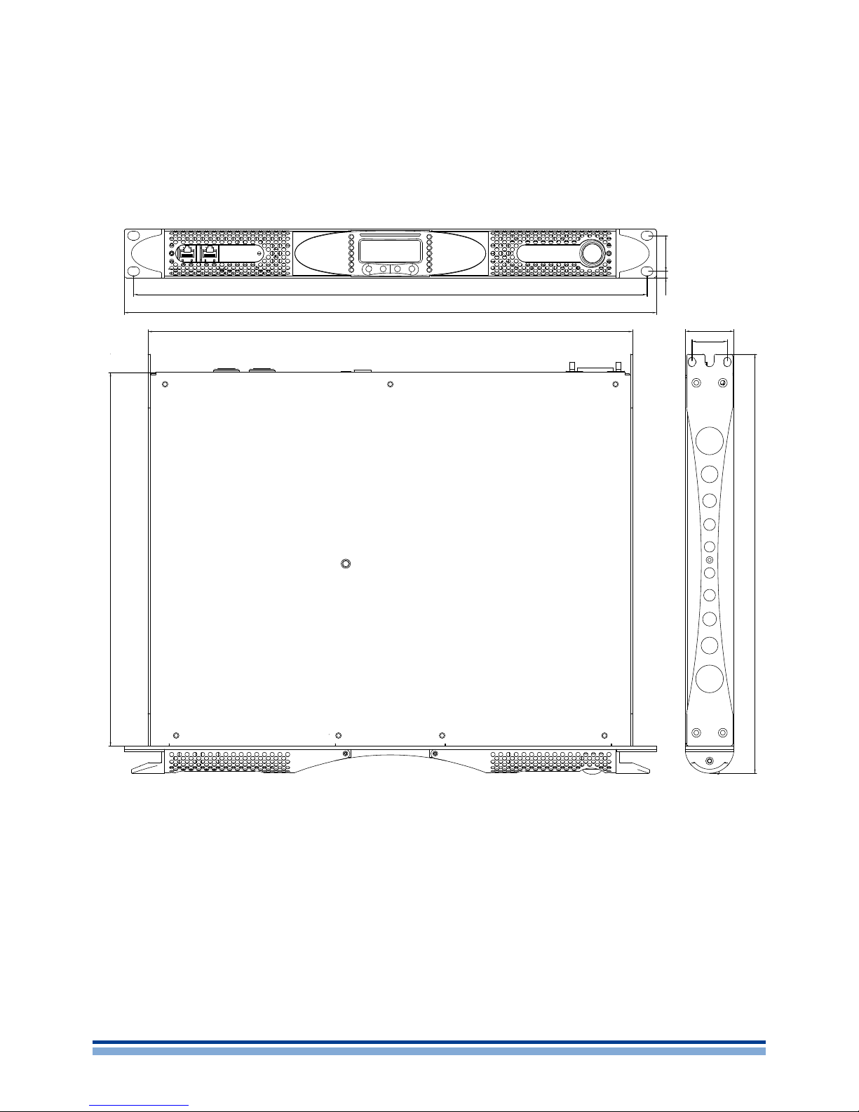
A
K2, K3
K2 DSP + AESOP, K3 DSP + AESOP
465
32.2
496
456
5.9
482
439 44
32
6 | K Series
Page 9

B
K6, K8, K10,
K6 DSP + AESOP, K8 DSP + AESOP, K10 DSP + AESOP
K20
K20 DSP + AESOP
465
32.2
465.4
472.4
5.9
482
440 44
32
K Series | 7
Page 10

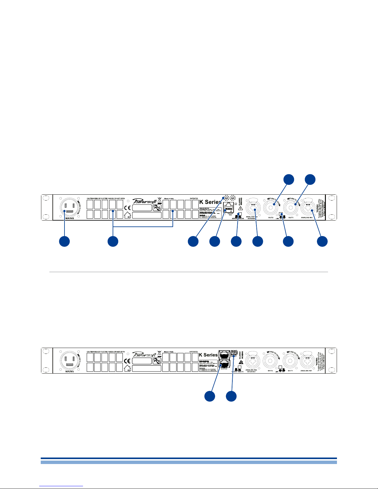
C
D
E
K2, K3
K2 DSP + AESOP, K3 DSP + AESOP
8 | K Series
A FB C D E G
1 2 93 5
14
4
13
6 7
12
8 10
11
Page 11

Front panel
A. RJ45 plugs (either AESOP or RS485 ports according to
the amplifier configuration)
B. LED bar: signal metering channel 1
C. Main display
D. Smart Card slot
E. Multifunction buttons
F. LED bar: signal metering channel 2
G. Main switch
Rear panel
1. Mains inlet
2. Air vents
3. Serial ID selector for the RS485 port
(non AESOP version only)
4. RS485 serial port (non AESOP version only)
5. AES3/analog switch for input 2
6. Input 2: channel 2 analog input in analog mode or
AES3 input in AES3 mode, according to the position of
the switch in #5
7. Line output channel 2
8. Link button: link input from channels 1 and 2
9. Line output channel 1
10. Input 1: channel 1 analog input
11. Speaker connector: output channel 1
12. Speaker connector: output channel 2
13. Ethernet+AESOP ports (AESOP version only)
14. Vext: 12 VDC, 1A external voltage input (AESOP
version only)
Panneau avant
A. Connecteurs RJ45 (soit ports RS485 ou AESOP selon
la configuration de l’amplificateur)
B. Barre de LED : mesurer le signal du canal 1
C. Écran principal
D. Fente pour carte à puce
E. Touches multifonctions
F. Barre de LED : mesurer le signal du canal 1
G. Interrupteur principal
Panneau arrière
1. Entrée d’alimentation secteur
2. Bouches d’aération
3. Sélecteur d’ID série pour le port RS485
(Version non AESOP seulement)
4. Port série RS485 (version non AESOP seulement)
5. Commutateur AES3 / analogique pour l’entrée 2
6. Entrée 2 : le canal d’entrée 2 analogique en mode
analogique ou l’entrée AES3 en mode A ES3, selon la
position du commutateur à # 5
7. Sortie ligne canal 2
8. Bouton Link : lien entrée des canaux 1 et 2
9. Sor tie ligne canal 1
10. Entrée 1 : entrée analogique du canal 1
11. Connecteur de haut-parleur : sortie du canal 1
12. Connecteur de haut-parleur : sortie du canal 2
13. Ports Ethernet + AESOP (version AESOP seulement)
14. Vext : entrée de tension externe 12V DC, 1A
(version AESOP uniquement)
Panel Frontal
A. Conectores RJ45 (ya sea AESOP o puertos RS485 de
acuerdo con la configuración de amplificador)
B. Barra LED: señal del canal 1
C. Pantalla principal
D. Ranura de tarjeta inteligente
E. Multifunción
F. Barra LED: señal del canal 2
G. Interruptor principal de alimentación
Panel Posterior
1. Conector de red de alimentación AC
2. Salidas de aire
3. Selector de ID para el puerto RS485
(Versión no AESOP solamente)
4. Puerto RS485
(Versión no AESOP solamente)
5. Interruptor AES3/analógica para la entrada 2
6. Entrada 2: canal de entrada 2 análogo en modo
analógico o la entrada AES3 en el modo de AES3,
según la posición del conmutador en el # 5
7. Canal de salida de línea 2
8. Conmutador de enlace: enlace de entrada de los
canales 1 y 2
9. Canal de salida de línea 1
10. Entrada 1: canal de entrada 1 análogo
11. Conector de altavoz: canal de salida 1
12. Conector de altavoz: canal de salida 2
13. Puertos de ethernet+AESOP
(Versión AESOP solamente)
14. Vext: 12 VDC, 1A entrada de tensión externa
(Versión AESOP solamente)
English Française Español
K Series | 9
Page 12
F
G
K6, K8, K10, K20
K6 DSP + AESOP, K8 DSP + AESOP, K10 DSP + AESOP, K20 DSP + AESOP
10 | K Series
1 2 4
12
3
11
5 6
10
7 8
9
Page 13

English Française Español
Rear panel
1. Mains plug
2. Air vents
3. Serial ID selector for the RS485 port
(non AESOP version only)
4. RS485 serial port (non AESOP version only)
5. AES3/analog switch for input 2
6. Input 2: channel 2 analog input in analog mode or
AES3 input in AES3 mode, according to the position of
the switch in #5
7. Link button: link input from channels 1 and 2
8. Input 1: channel 1 analog input
9. Speaker connector: output channel 1
10. Speaker connector: output channel 2
11. Ethernet+AESOP ports (AESOP version only)
12. Vext: 12 VDC, 1A external voltage input (A ESOP
version only)
Panneau arrière
1. Entrée d’alimentation secteur
2. Bouches d’aération
3. Sélecteur d’ID série pour le port RS485
(Version non AESOP seulement)
4. Port série RS485 (version non AESOP seulement)
5. Commutateur AES3 / analogique pour l’entrée 2
6. Entrée 2 : le canal d’entrée 2 analogique en mode
analogique ou l’entrée AES3 en mode A ES3, selon la
position du commutateur à # 5
7. Bouton Link : lien entrée des canaux 1 et 2
8. Entrée 1 : entrée analogique du canal 1
9. Connecteur de haut-parleur : sortie du canal 1
10. Connecteur de haut-parleur : sortie du canal 2
11. Ports Ethernet + AESOP (version AESOP seulement)
12. Vext : entrée de tension externe 12V DC, 1A
(version AESOP uniquement)
Panel Posterior
1. Conector de red de alimentación AC
2. Salidas de aire
3. Selector de ID para el puerto RS485
(Versión no AESOP solamente)
4. Puerto RS485
(Versión no AESOP solamente)
5. Interruptor AES3/analógica para la entrada 2
6. Entrada 2: canal de entrada 2 análogo en modo
analógico o la entrada AES3 en el modo de AES3,
según la posición del conmutador en el # 5
7. Conmutador de enlace: enlace de entrada de los
canales 1 y 2
8. Entrada 1: canal de entrada 1 análogo
9. Conector de altavoz: canal de salida 1
10. Conector de altavoz: canal de salida 2
11. Puertos de ethernet+AESOP
(Versión AESOP solamente)
12. Vext: 12 VDC, 1A entrada de tensión externa
(Versión AESOP solamente)
K Series | 11
Page 14
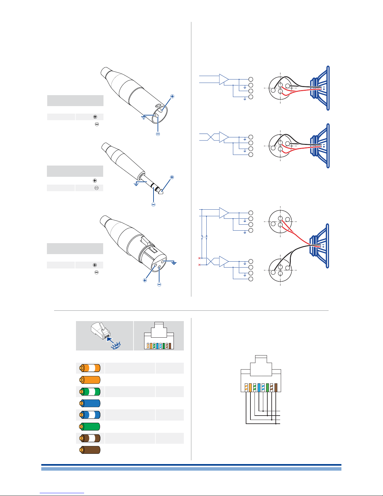
H
J K
I
1 2 3 4 5 6 7 8
Color code (TIA/EIA-568-B) Pin
ORANGE / WHITE 1
ORANGE 2
GREEN / WHITE 3
BLUE 4
BLUE / WHITE 5
GREEN 6
BROWN / WHITE 7
BROWN 8
Analog input
XLR-M pinout
Pin 1 GND
Pin 2
HOT
Pin 3
COLD
Analog input
TRS Jack pinout
Tip
HOT
Ring
COLD
Sleeve GND
A
C
B
HOT
HOT
1
S
2
R
3
T
COLD
COLD
GND
GND
Analog line output
XLR-F pinout
Pin 1 GND
Pin 2
HOT
Pin 3
COLD
HOT
1
2
3
COLD
GND
Bridge-tied load
speakON
connector
Channel 2
output
stage B
LINK
CHB +
CHB +
CHB –
CHB –
B
speakON
connector
Channel 1
output
stage A
CHA +
CHA +
CHA –
CHA –
A
CH1
CH2
Single-ended load
Single-ended load
speakON
connector
Channel 2
output
stage B
CHB +
CHB +
CHB –
CHB –
B
speakON
connector
Channel1
output
stage A
CHA +
CHA +
CHA –
CHA –
A
1+
2+
1–
2–
1+
2+
1–
2–
1+
2+
1–
2–
1+
2+
1–
2–
1+
2+
1–
2–
1+
2+
1–
2–
1+
2+
1–
2–
1+
2+
1–
2–
1
+
–
V
ext
GND
2 3 4 5 6 7 8
12 | K Series
RS485
Ethernet
Page 15
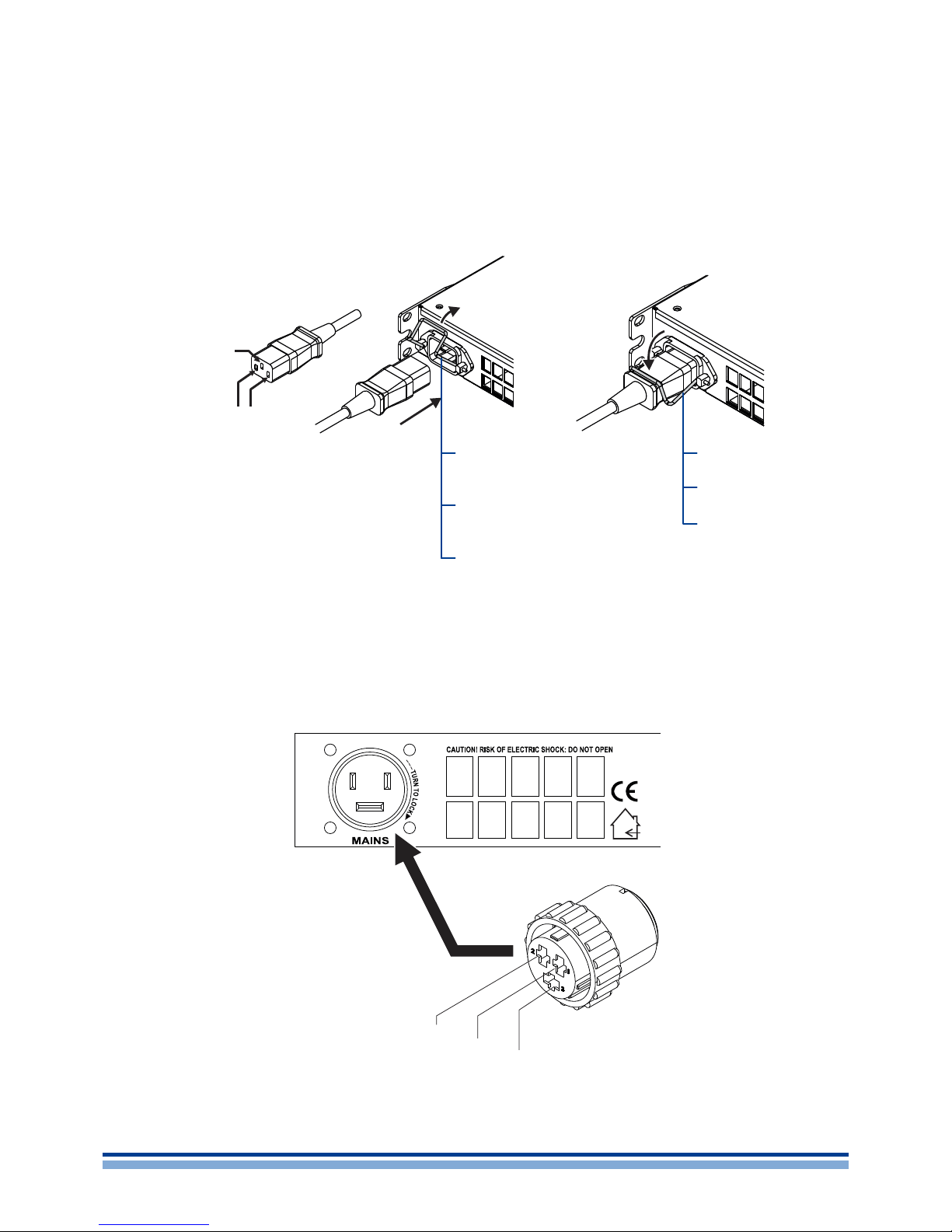
K6, K8, K10, K20
K6 DSP + AESOP, K8 DSP + AESOP, K10 DSP + AESOP, K20 DSP + AESOP
K2, K3
K2 DSP + AESOP, K3 DSP + AESOP
Open the lock and
insert the plug
Ouvrir le verrou
et insérer la che
Abra el seguro y
conecte la clavija
Lock the plug
Bloquer la che
Asegure la clavija
L
ground
mains
ground
mains
N
Neutral
L
32 1
K Series | 13
Page 16

M
lock
mute mute menu
CH1 READY READY CH2
V I VI
Display
Local presets
Setup
Menu
Settings
Amplier Settings
DSP Settings
1
Network Settings
2
Output meters
Temperature
Mains meters
Amplier name
Lock presets
Locked bank size
Recall local preset
Save local preset
Change lock code
Erase all presets
Hardware Info
Hardware Monitor
LCD contrast
Set Keylock code
Service
Source selection
Source mode
Gain trim
If no link
Display Amp data
Edit Amplier name
Analog Out
Analog DSP Out
AES3 Out
AES3 DSP Out
KAESOP Out
KAESOP DSP Out
Output attenuation
Input gain/sens
Inuput select
Max output voltage
Max mains current
Clip limiter CH1
Clip limiter CH2
Gate CH1
Gate CH2
Mute at Power on
Idle Mode
see “DSP Settings” diagram
Device mode
Addressing mode
Set address
Show net cong
Audio
Repeat (default)
Forward to AES3-A
Forward to AES3-B
Forward to both
IP address
subnet mask
Default gateway
1
Available only with optional KDSP board
2
Available only with optional KAESOP board
14 | K Series
Page 17
Source selection
Source mode
Gain trim
If no link
AES3-XLR rear panel
AES3-A
AES3-B
Parallel from L
Parallel from R
Stereo
Mute
Analog
Display Amp data
Edit Amplier name
Analog Out
Analog DSP Out
1
AES3 Out
1
AES3 DSP Out
1
KAESOP Out
2
KAESOP DSP Out
1, 2
Output attenuation
Input gain/sens
Inuput select
Max output voltage
Max mains current
Clip limiter CH1
Clip limiter CH2
Gate CH1
Gate CH2
Mute at Power on
Idle Mode
see “DSP Settings” diagram
Device mode
Addressing mode
Set address
Show net cong
Audio
Repeat (default)
Forward to AES3-A
Forward to AES3-B
Forward to both
IP address
subnet mask
Default gateway
1
Available only with optional KDSP board
2
Available only with optional KAESOP board
K Series | 15
N
Page 18
N
Common Settings
CH1 Settings
CH2 Settings
CH1 Setup
CH2 Setup
Input EQ
Reset Input Section
Reset Output Section
Source Selection
AES3
Cross limit
Sound speed (m/s)
Gain trim (dB)
If no link:
EQs
LP lter
HP lter
Polarity
Ch delay (us)
Gain (dB)
Peak limiter
Power limiter
Damping Control
PEQ#
Stereo
Parallel from CH1
Parallel from CH2
Mono Mix
Active
Freq. (Hz)
Slope (dB/oct)
Shape
Active
Freq. (Hz)
Slope (dB/oct)
Shape
In phase
Reversed
Active
Thresh. (Vpk)
Attack (ms)
Release (ms)
Mode
Soft knee
Thresh. (W)
Attack (ms)
Release (ms)
Mode
Equiv. Rout (Ω)
Aux Dly (ms)
Diagnostics
Tone in alarm
Tone in freq
Tone in Vmin
Tone in Vmax
Tone out gen
Tone out ampl
Tone out freq
Tone out alarm
Tone out Vmin
Tone out Vmax
Load alarm
Load Zmin
Load Zmax
Measures
identical to CH1 Settings
identical to CH1 Setup
Analog
Mute
Active
Freq. (Hz)
Gain (dB)
Q factor
Type
Peaking
Low Shelving
High Shelving
Low pass EQ
High pass EQ
Bandstop
Bandpass
Allpass
Butterworth
Bessel
Link.-Riley
FIR Lin Phase
Hybrid FIR
Butterworth
Bessel
Link.-Riley
FIR Lin Phase
Hybrid FIR
OFF
TruePower
Power vs V @ 8Ω
Power vs I @ 8Ω
16 | K Series
Page 19

O
Load power
estimation
INPUT
PROCESSING
INPUT
SELECT
CHANNEL
PROCESSING
DAMPING
CONTROL
TruePOWER
LIMITER
PEAK
LIMITER
POLARITY
Hi-PASS
FILTER
Lo-PASS
FILTER
CHANNEL
DELAY
FIR EQ
Output current
Output voltage
output
monitor
16 bands parametric EQ Custom FIR Enhanced limiter
Cable loss
compensationIIR and FIR linear phase crossover
CHANNEL
PEQ16
Load impedance
estimation
GAIN
MAIN
DELAY
INPUT EQGAIN
GAIN
AES3
Analog
To/from
other channel
SigGen SigGen
To output stage
Raised cosine lters EQ
K Series | 17
Page 20
P
Q
11
1 RU
1 RU
1 RU
Mounting brackets
Soportes de montaje
Supports de xation
1
1
22
22
33
33
44
44
5
18 | K Series
Page 21

R
Regulatory information
WEEE DIRECTIVE
If the time arises to throw away your product, please recycle all the components possible.
This symbol indicates that when the end-user wishes
to discard this product, it must be sent to separate collection facilities for recovery and recycling. By separating this product from other household-type waste, the
volume of waste sent to incinerators or land-fills will be
reduced and natural resources will thus be conserved.
The Waste Electrical and Electronic Equipment Directive ( WEEE Directive)
aims to minimise the impact of electrical and electronic goods on the environment. Powersoft S.p.A. comply with the Directive 2002/96/EC and
2003/108/EC of the European Parliament on waste electrical finance the
cost of treatment and recovery of electronic equipment (WEEE) in order
to reduce the amount of WEEE that is being disposed of in land-fill site.
All of our products are marked with the WEEE symbol; this indicates that
this product must NOT be disposed of with other waste. Instead it is the
user’s responsibility to dispose of their waste electrical and electronic
equipment by handing it over to an approved reprocessor, or by returning it to Powesoft S.p.A. for reprocessing. For more information about
where you can send your waste equipment for recycling, please contact
Powesoft S.p.a. or one of your local distributors.
EC DECLARATION OF CONFORMITY
Manufacturer:
Powersoft S.p.A.
via E. Conti 5
50018 Scandicci (Fi)
Italy
We declare that under our sole responsibility the products:
Model Names: K2, K3, K6, K8, K10, K20
K2 DSP+AESOP, K3 DSP+AESOP,
K6 DSP+AESOP, K8 DSP+AESOP, K10 DSP+AESOP,
K20 DSP+AESOP.
Intended use: Professional Audio Amplifier
Are in conformity with the provisions of the following EC Directives,
including all amendments, and with national legislation implementing
these directives:
2006/95/EC Low Voltage Directive
2004/108/EC Electromagnetic Compatibility Directive
2002/95/CE RoHs Directive
The following armonized standards are applied:
EN 55103-1
EN 61000-3-2
EN 61000-3-3
EN 55103-2
EN 61000-4-2
EN 61000-4-3
EN 61000-4-4
EN 61000-4-5
EN 61000-4-6
EN 61000-4-11
EN 60065
Scandicci,
July 2014
Luca Lastrucci
Managing Director
For compliance questions only: compliance@powersoft.it
K Series | 19
Page 22
English
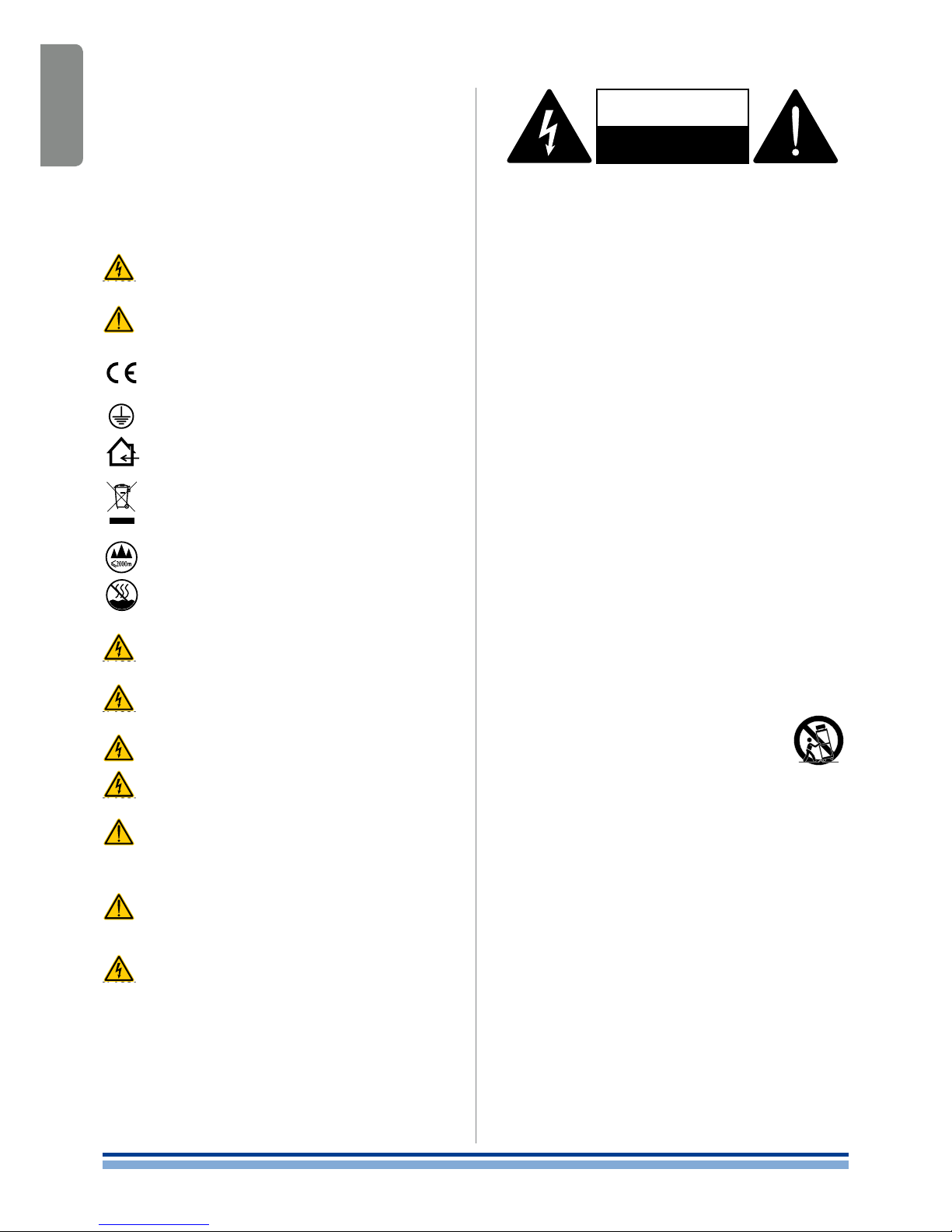
CAUTION
RISK OF ELECTRICK SHOCK
DO NOT OPEN
Electrical energy can perform many useful functions. This unit has
been engineered and manufactured to ensure your personal safety. But
IMPROPER USE CAN RESULT IN POTENTIAL ELECTRICAL SHOCK OR
FIRE HAZARD.
In order not to defeat the safeguards incorporated into this product,
observe the following basic rules for its installation, use and service.
Please read these “Important Safeguards” carefully before use.
Important safety instructions
1. Read these instructions.
2. Keep these instructions.
3. Heed all warnings.
4. Follow all instructions.
5. Do not use this equipment near water.
6. Clean only with a dry cloth.
7. Do not block any ventilation openings. Install in accordance with
the manufacturer’s instructions.
8. Do not install near any heat sources such as radiators, heat registers,
stoves, or other apparatus (including amplifiers) that produce heat.
9. Do not defeat the safety purpose of the polarized or groundingtype plug. A polarized plug has two blades with one wider than the
other. A grounding type plug has two blades and a third grounding
prong. The wide blade or the third prong are provided for your
safety. If the provided plug does not fit into your outlet, consult an
electrician for replacement of the obsolete outlet.
10. Protect the power cord from being walked on or pinched particularly at plugs, convenience receptacles, and the point where they
exit from the apparatus.
11. Only use attachments/accessories specified by the manufacturer.
12. Use only with the cart, stand, tripod, bracket, or table specified by
the manufacturer, or sold with the apparatus. When a
cart is used, use caution when moving the cart/apparatus combination to avoid injury from tip-over.
13. Unplug this apparatus during lightning storms or
when unused for long periods of time.
14. Refer all servicing to qualified service personnel. Servicing is
required when the apparatus has been damaged in any way, such
as power-supply cord or plug is damaged, liquid has been spilled
or objects have fallen into the apparatus, the apparatus has been
exposed to rain or moisture, does not operate normally, or has
been dropped.
Numbers 9 and 13 apply only to K2 and K3.
WARNING: TO REDUCE THE RISK OF ELECTRIC SHOCK, DO NOT
ATTEMPT TO OPEN ANY PART OF THE UNIT. NO USER-SERVICE ABLE
PARTS INSIDE. REFER SERVICING TO QUALIFIED SERVICE PERSONNEL.
TO COMPLETELY DISCONNECT THIS APPARATUS FROM THE AC
MAINS, DISCONNECT THE POWER SUPPLY CORD PLUG FROM THE AC
RECEPTACLE.*
THE MAINS PLUG OF THE POWER SUPPLY CORD MUST
REMAIN READILY ACCESSIBLE.**
DO NOT EXPOSE THIS EQUIPMENT TO RAIN OR MOISTURE, DRIPPING
OR SPLASHING LIQUIDS. OBJECTS FILLED WITH LIQUIDS, SUCH AS
VASES, SHOULD NOT BE PLACED ON THIS APPARATUS
K6, K8, K10 AND K20 MUST BE INSTALLED IN RACK CABINETS:
INSTEAD OF CONNECTING THE AMPLIFIER TO THE POWER GRID
DIRECTLY, PLUG THE AMPLIFIER’S MAINS CONNECTIONS VIA A
SECTIONING BREAKER TO A POWER DISTRIBUTION PANEL INSIDE
THE RACK CABINET.
WHEN THE UNIT IS INSTALLED IN A CABINET OR A SHELF, MAKE
SURE THAT IT HAS SUFFICIENT SPACE ON ALL SIDES TO ALLOW
FOR PROPER VENTILATION (50 CM FROM THE FRONT AND REAR
VENTILATION OPENINGS).
CONNECTION TO THE MAINS SHALL BE DONE ONLY BY A
ELECTROTECHNICAL SKILLED PERSON ACCORDING THE NATIONAL
REQUIREMENTS OF THE COUNTRIES WHERE THE UNIT IS SOLD.
EXPLANATIONS OF GRAPHICAL SYMBOLS
The triangle with the lightning bolt is used to alert the user to the
risk of electric shock.
The triangle with the exclamation point is used to alert the user
to important operating or maintenance instructions.
The CE-mark indicates the compliance with the low voltage and
electromagnetic compatibility.
Symbol for earth/ground connection.
Symbol indicating that the equipment is for indoor use only.
Symbol for conformity with Directive 2002/96/EC and Directive
2003/108/EC of the European Parliament on waste electrical
and electronic equipment (WEEE).
Do not use the unit at altitudes above 2000 m.
Do not use the unit in tropical environment.
Important safety
instructions
1
* K6, K8, K10 and K20: interrupt the mains by switching the sectioning
breaker off.
** Valid for K2 and K3 model only; with K6, K8, K10 and K20 a free leads
power cord (i.e. without plug) is provided: this solution is intended for connecting the device to a sectioning breaker on the mains. Refer to the installation instruction for selecting the proper sectioning breaker.
20 | K Series
Page 23

English
K Series Quick Guide
2
2 : 1.Welcome
Congratulations on buying a Powersoft K Series amplier!
We know you are eager to use your new amplier, but
please take a moment to read this user’s manual and safety
instructions. In case you have any questions, please do not
hesitate to contact your dealer or Power soft.
Powersoft K Series is the agship of Powersoft’s
technologies, ranking in the “Top Class” amplication of the
global pro audio market.
Offering various power ratings in 6 models ranging from
2 x 2400 W/ch @ 4 to 2 x 9000 W/ch @ 2 , still maintaining
the 1 unit size, the K Series represents the milestone of
switch mode amplication providing incredible power with
the lowest weight and highest efciency.
Suiting an unlimited range of PA applications such as
opera houses, theaters, churches, cinema, and theme
parks, K Series sonic performances became target for
professional audio market.
Completely remotable by Armonía Pro Audio Suite,
Powersoft K Series DSP+AESOP grants granular control
over any parameter of the signal processing: input/output
independent equalizers per channel providing PEQ, raised
cosine, shelving IIR lters as well as custom output FIR lters,
delay up to 1 s for time alignment, Active DampingControl™
for cable compensation, Power limiter (TruePower™, RMS
voltage, RMS current) + Peak Limiter.
Furthermore, by using the Step-Up procedure it is
possible to increase the output power without having to
change amplier.
K Series ampliers are:
K2
K2 DSPK3K3 DSPK6K6 DSPK8K8 DSP
K10
K10DSP
K20
K20DSP
8 Ω 1000 W 1400 W 1300 W 1500 W 2000 W 2700 W
4 Ω 1950 W 2600 W 2500 W 3000 W 4000 W 5200 W
2 Ω 2400 W 2800 W 3600 W 4800 W 6000 W 9000 W
2 : 2.Unpacking & checking for shipping damage
Your Powersoft product has been completely tested and
inspected before leaving the factory. Carefully inspect the
shipping package before opening it, and then immediately
inspect your new product. If you nd any damage, notify the
shipping company or reseller immediately.
The box contains the following:
1x K Series amplier.
1x AC mains power cord
1x quick guide
2 : 3.Disposal of the packaging material
The protective transport packaging has been selected
from materials which are environmentally friendly for disposal and can normally be recycled.
Rather than just throwing these materials away,
please ensure they are offered for recycling.
2 : 4.List of image panels
A. K2, K3 mechanical drawings (dimensions in mm)
B. K6, K8, K10, K 20 mechanical drawings (dimensions in mm)
C. K Series front panel
D. K2, K3 rear panel
E. K2 DSP+AESOP, K3 DSP+AESOP rear panel
F. K6, K8, K10, K20 rear panel
G. K6 DSP+AESOP, K8 DSP+AESOP, K10 DSP+AESOP,
K20 DSP+AESOP rear panel
H. Connectors pinout
I. Output connections diagram
J. RJ45 Ethernet pinout
K. RJ45 RS485 pinout
L. AC mains connections
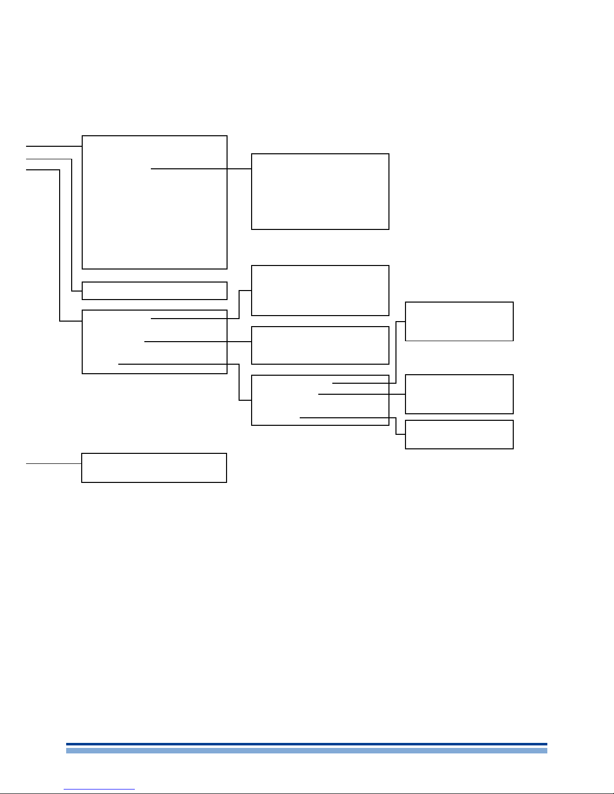
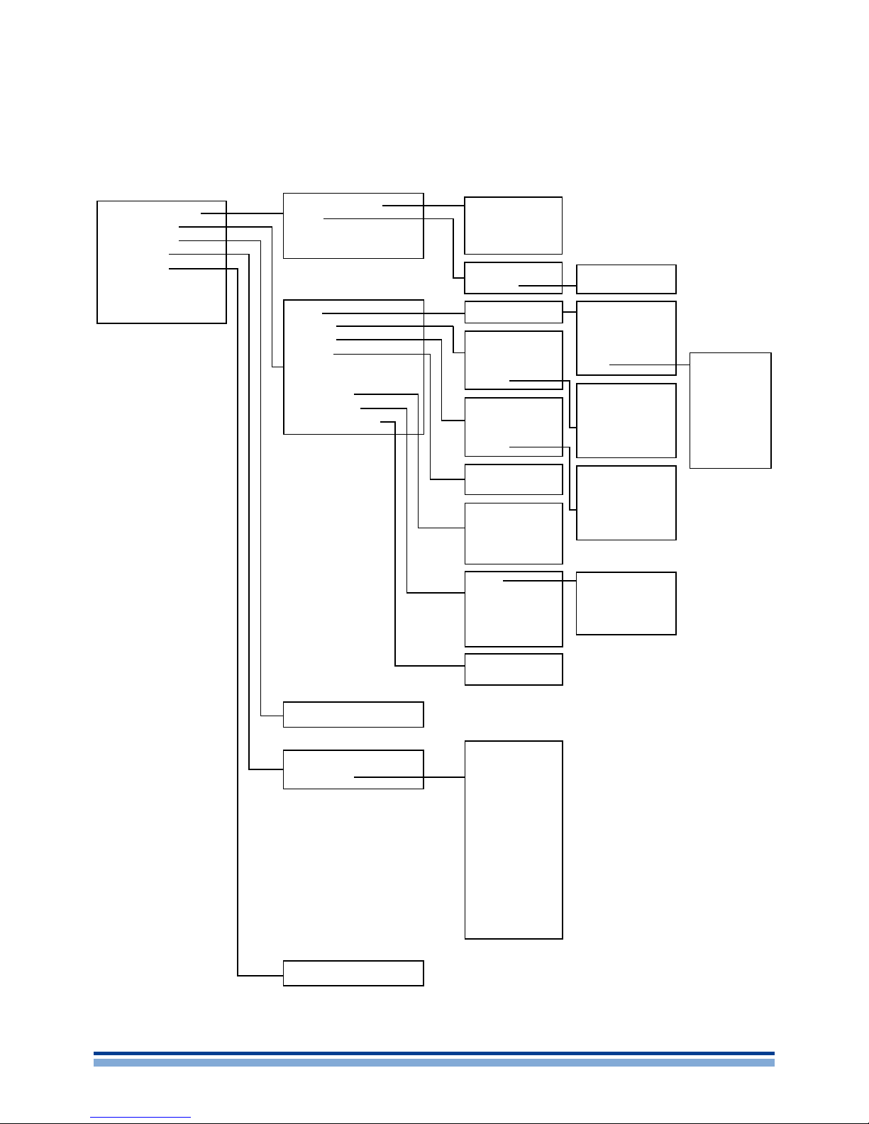
M. LCD: main settings menu diagram
N. LCD: DSP settings menu diagram
O. Signal processing diagram
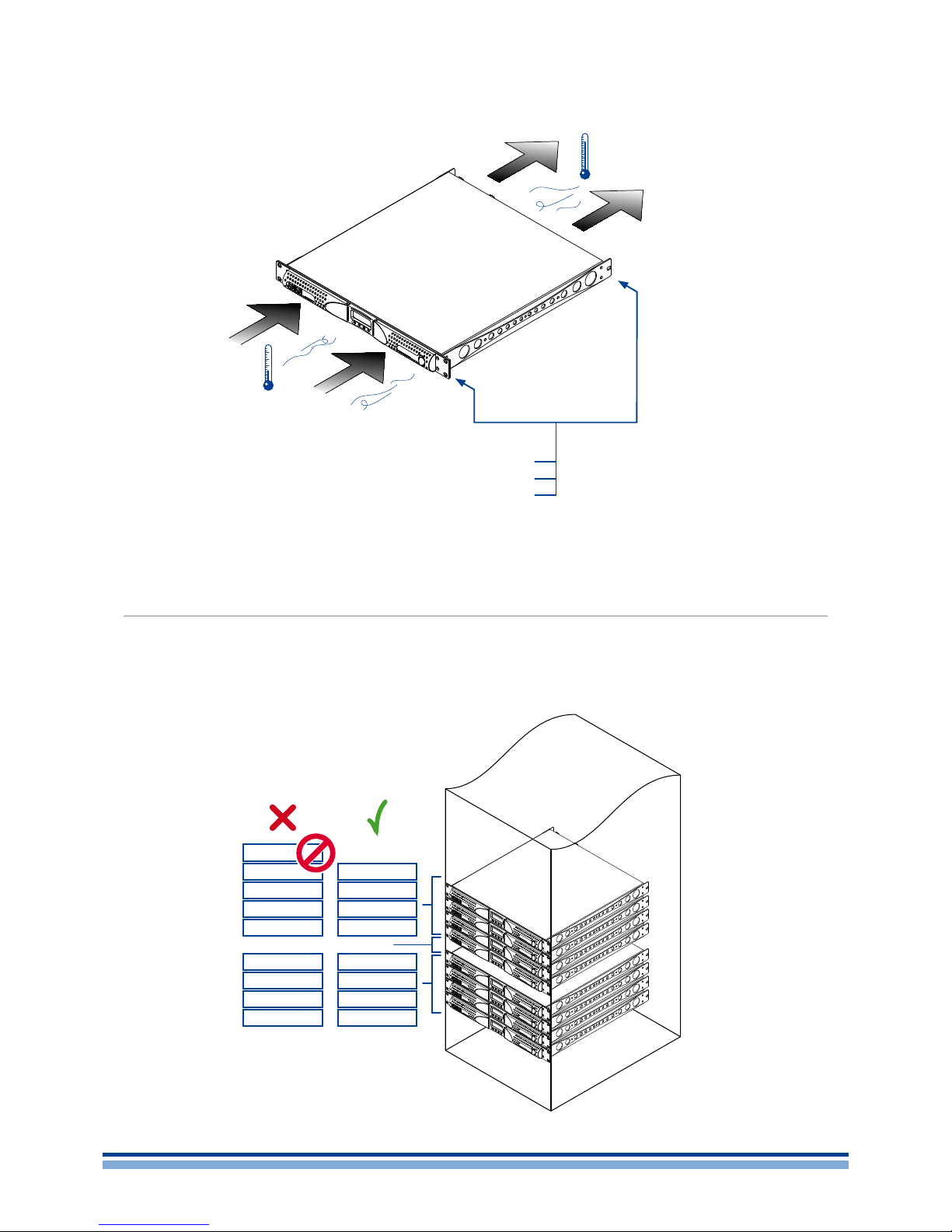
P. Mounting brackets and air ow direction
Q. Rule for stacking ampliers in closed racks
R. Regulatory information
English | 21
Page 24
English
Installation
3
3 : 1.Location
The intended use of K Series ampliers is in a rack cabinets. The AC mains wirings of the units shall be connected
to a power distribution panel inside the rack cabinet. In
order to limit the risk of mechanical damages, the ampliers
must be xed to the rack using both frontal and rear mounting brackets. We recommends to use eight M6 or 12-24
UNC-2B screws for threaded holes or cage nuts.
Install this amplier as far as possible from radio tuners
and TV sets. An amplier installed in close proximity of such
equipment may experience noise or generic performance
degradation. Placing and using the amplier for long periods
of time on heat generating sources will affect its performance.
Avoid placing the amplier on heat generating sources.
3 : 2.Cooling
Install the amplier in a well-ventilated location: the ventilation openings must not be impeded by any item such as
newspapers, tablecloths, curtains, etc; keep a distance of
at least 50 cm from the front and rear ventilation openings
of the amplier.
All Powersoft ampliers implement a forced-air cooling
system to maintain low and constant operating temperatures. Drawn by the internal fans, air enters from the front
panel and is forced over all components, exiting at the back
of the amplier.
The amplier’s cooling system features “intelligent” variable-speed DC fans which are controlled by the heatsink
temperature sensing circuits: the fans speed will increase
only when the temperature detected by the sensors rises
over carefully predetermined values. This ensures that fan
noise and internal dust accumulation are kept to a strict
minimum.
Should however the amplier be subject to an extreme
thermal load, the fan will force a very large volume of air
through the heat sink. In the extremely rare event that the
amplier should dangerously overheat, sensing circuits
shut down all channels until the amplier cools down to a
safe operating temperature. Normal operation is resumed
automatically without the need for user intervention.
K Series ampliers can be stacked one on top of the other
due to the efcient cooling system they are equipped with.
There is however a safety limit to be observed: in case
a rack with closed back panels is used, leave one rack unit
empty every four installed ampliers to guarantee adequate air
ow (see Panel Q, p. 18).
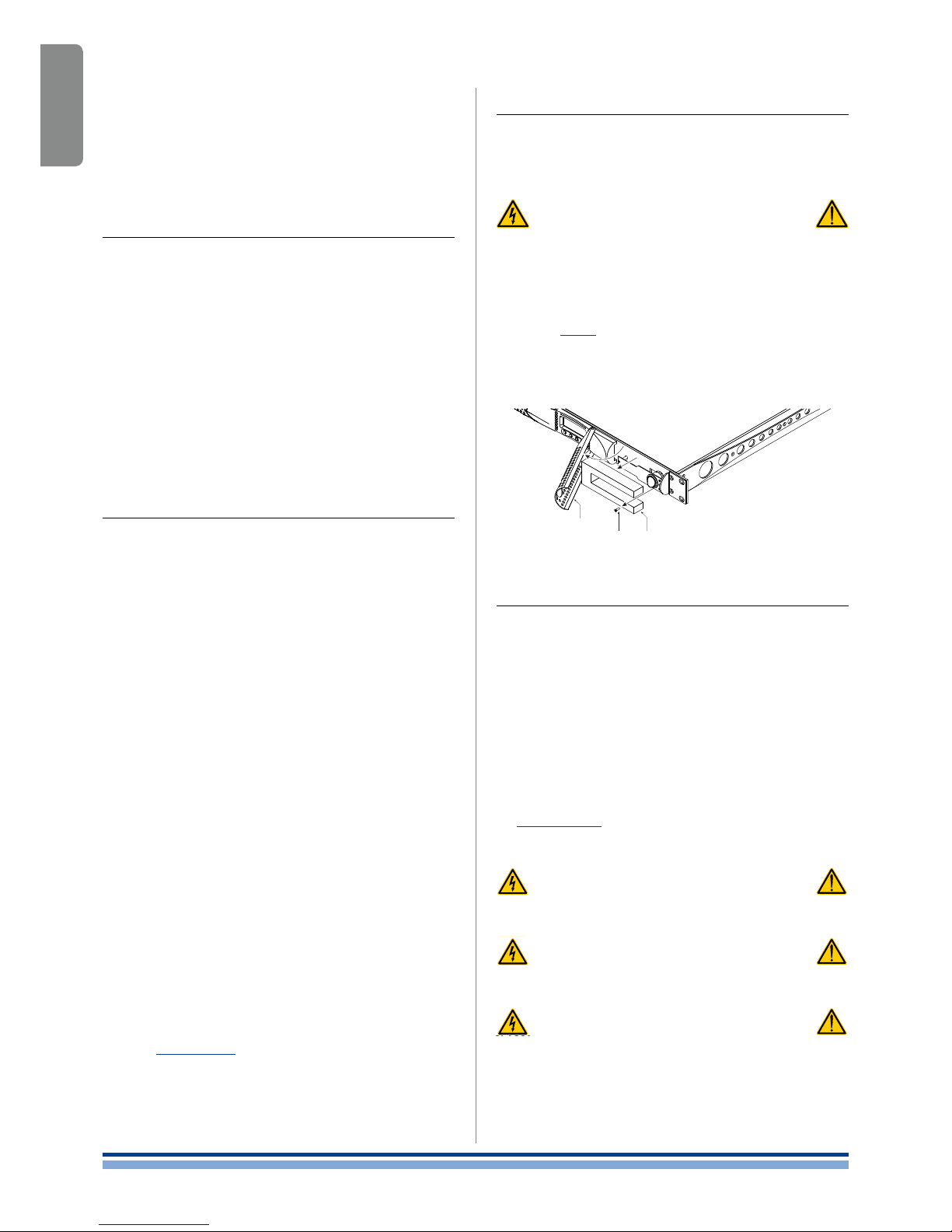
3 : 3.Cleaning
Always use a dry cloth for cleaning the chassis and the
front panel. Air lter cleaning should be scheduled according
to the dust levels in the amplier’s operating environment.
Disconnect the AC mains source before
attempting to clean any part of the amplifier
In order to clean the vent lters you need to remove the
front cover: never attempt to open any other part of the unit.
By means of a screwdriver Phillips PH1, unscrew the
screws that lock the left and right cover grils on the front
panel (ref. FIG. 1), gently lift the covers and remove the lters. You may use compressed air to remove the dust from
lters, or wash it with clean water: in the latter case ensure
that the lters are dry before reassembly.
3 : 4.AC mains supply
The AC Main connection is made via the
AMP CPC 45A connector in K6, K8, K10 and K20;
IEC C20 connector in K3 and K2.
The power cord type provided with the amplier are
LAPP OLFLEX191 3G6 / SJT 3XAWG10
for K6, K8, K10 and K20.
Bahoing SJT 3x16AWG or I-sheng SGIS 3G 1,5 mm
2
for K3 - K2.
Panel L, p. 13 shows how to connect the mains power
cable to the amplier.
Make sure the AC mains voltage used
is within the acceptable operating
voltage range: 115V-230V ±10%.
It is important to connect the ground
for safety, do not use adapters that
disable the ground connection.
Connection to the mains shall be done
only by a electrotechnical skilled person
according the national requirements of
the countries where the unit is sold.
cover grill
screw lter
FIG. 1: Cleaning air filters.
22 | K Series
Page 25

English
Connections
4
Make sure the power switch is off before attempting to
make any input or output connections.
By using good quality input and speaker cables, the likelihood of erratic signal behavior is reduced to a minimum.
Whether you make them or buy them, look for good quality
wires, connectors and soldering techniques.
4 : 1.Signal grounding
There is no ground switch or terminal on the K Series
ampliers. All shield terminals of input connections are directly connected to the chassis. This means that the unit’s
signal grounding system is automatic. In order to limit hum
and/or interference entering the signal path, use balanced
input connections.
In the interests of safety, the unit MUST always operate
with electrical safety earth connected to the chassis via
the dedicated wire in the 3-wire cable (ref. §3 : 4.AC ma ins
supply). Never disconnect the ground pin on the AC mains
power cord.
4 : 2.Analog audio input connections
Analog input is provided by means of Neutrik XLR female
connectors (K2, K3), or XLR/jack hybrid combo connectors
(K6, K8, K10, K20) one per channel input. Signal polarity of
analog input connections is shown in Panel H, p. 12.
4 : 3.Analog line output
Line out is provided in K2 and K3 via a couple of XLR
connectors on the rear panel. In DSP equiped models, the
output signal is pre-DSP, being a replica of the input signal.
Signal polarity of line output connections is shown in Panel
H, p. 12.
4 : 4.Digital Input
On DSP equiped models, the XLR input for channel 2
can switch to an AES3 digital input. The AES3/analog pushbutton located nearby the channel 2 XLR input connector
toggles the XLR between analog and digital input.
In AES3 mode
the channel 2 analog line out is off (K2, K3 only);
the channel 1 analog input can be used as redundant
input if the digital input fails.
The AES3 connection carries a channel pair through a
110 nominal impedance wire in the form of a balanced
(differential) digital signal: in AES3 XLR connectors the
identication of hot and cold pins is not an issue. Avoid the
use of microphone cables in AES connections: impedance
mismatch can result in signal reections and jitter, causing
bit errors at the receiver.
3 : 5.Precautions regarding installation
WARNING: TO PREVENT FIRE OR ELECTRIC SHOCK
This device must be powered exclusively by earth con-
nected mains sockets in electrical networks compliant
to the IEC 364 or similar rules.
Install K6, K8, K10 and K20 into rack cabinet.
With K6, K8, K10 and K20 a sectioning breaker be-
tween the mains connections and the amplier must
be installed inside the rack cabinet. Suggested device
is 32A/250VAC, C or D curve, 10kA.
With K2 and K3 provide a sectioning breaker between
the mains connections and the amplier. Suggested
device is 16A/250VAC, C or D curve, 10kA.
Before powering this amplier, verify that the correct
voltage rating is being used.
Verify that your mains connection is capable of satisfy-
ing the power ratings of the device.
Do not use this amplier if the electrical power cord is
frayed or broken.
Output terminals are hazardous: wiring connection to
these terminals require installation by an instructed
person and the use of ready-made leads.
Take care to lock the output terminal before switching
the device on.
To avoid electrical shock, do not touch any exposed
speaker wiring while the amplier is operating.
Do not spill water or other liquids into or on the amplier.
No naked ame sources such as lighted candles
should be placed on the amplier.
Do not remove the cover. Failing to do so will expose
you to potentially dangerous voltage.
The manufacturer cannot be held responsible for
damages caused to persons, things or data due to an
improper or missing ground connection.
Contact the authorized service center for ordinary and
extraordinary maintenance.
It is absolutely necessary to verify these fundamental
requirement of safety and, in case of doubt, require
an accurate check by qualified personnel.
English | 23
Page 26
English
4 : 5.AESOP
The AESOP connection can transport a single bidirectional Fast Ethernet (IEEE 802.3u, 100 Mbit/s) control data
stream and two independent separate AES3 digital audio
monodirectional streams using one Cat5 cable.
All K Series amplier with the optional KAESOP board
installed are equipped with at least two RJ45 connectors,
each of them being a single AESOP port, capable of sending and/or receiving data and audio.
If the amplier has only two RJ45 plugs, these will be
on the front panel. If four plugs are present, the rear two
will be “primary” ports, while the two on the front panel are
“secondary” ports.
Primary ports allow both data and AES3 streams; secondary ports are data-only ports, allowing Ethernet connections only.
Cat5 standard twisted pair cables shall be used for connections up to 100 meters (328 ft). RJ45 pinout must comply
to TIA/EIA-568-B and adopt the T568B scheme pinout, as
show in Panel J, p. 12.
For more details about networking and AESOP please
refer to the Armonía Pro Audio Suite user guide.
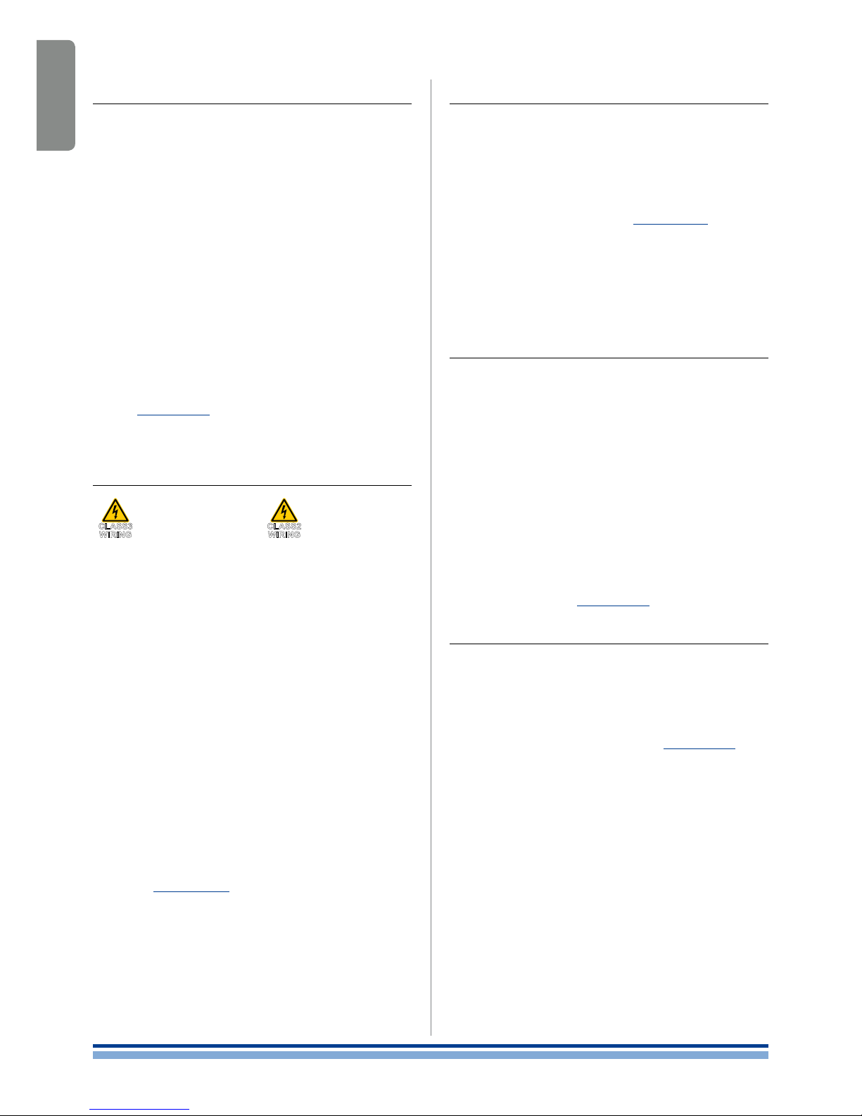
4 : 6.Loudspeaker connections
K6, K8, K10, K20 K2, K3
CLAS S 3 WIR ING CLASS2 WIRING
Output terminals are hazardous: wiring connection
to these terminals require installation by an
instructed person and the use of ready made leads.
Take care to secure the output terminal
before switching the device on.
Two Neutrik NL4MD speakON connectors are located
on the rear panel, each of them being a single output to
loudspeaker.
Pins 1+ and 2+ are physically bridged to the positive pole;
pins 1– and 2– are physically bridged to the negative pole.
In order to remain within safe operating conditions,
when using low impedance loads – i.e. 4 Ω or less (8 Ω or
less in bridge mode) –, connections must be made with a
four wire cable. Use suitable wire gauges to minimize power
and damping factor losses in speaker cables.
4 : 6.1. Bridge-tied load
Bridge-tied load connection can be achieved as described in Panel I, p. 12. In analog mode, only the input
of channel 1 needs to be wired: link channel 2 to channel 1
by means of the link pushbutton located on the rear panel.
When operating with digital inputs – i.e. AES3 and AESOP
– link the channels through Armonía Pro Audio Suite software:
do not switch the link pushbutton.
CLASS3
WIRING
CLASS2
WIRING
4 : 7.V Ext
The V Ext terminal is used to remotely manage the DSP
in K Series DSP amplier and enable remote on/off.
K Series provided with a KAESOP board have a dedicated 2 pin Phoenix connector MCV 1,5/ 2-G-3,81 - 1803426
located near the rear Ethernet ports. K Series with the RS485 serial port implement the V Ext connection on pin 2 (pin
7) of the RJ45 rear connector (ref. Panel K, p. 12).
When the V Ext port is powered by and external 12 V
DC
(1 A max) power supply, the internal controller allows to control the DSP – if present – even without AC mains supply,
and allows serial communication – via RS-485 or ethernet
communication in KAESOP equiped models – for remote
on/off via the Armonía Pro Audio Suite software.
4 : 8.RS-485 connection
K Series ampliers without an optional KAESOP board
can be remotely controlled via an RS-485 connection.
Remote connection data cables must have an 8P8C
modular plug – namely RJ45 plug – to be inserted in the
rear port labelled “DATA PORT”.
By plugging an RJ45 plug and selecting the unit’s remote
ID via the rotary trimmers, the amp is ready to be remotely
controlled. Please note that ID numer 00 is not allowed.
The recommended arrangement of the connections is a
series of point-to-point (multidropped) nodes – i.e. a line or
bus. Ideally, the two ends of the line should be terminated
with a resistor, typically 120 Ω for twisted pairs. Powersoft
recommends the use of Ethernet Cat5 straight through –
patch – cables with pin/pair assignments TIA/EIA-568-B,
i.e. T568B, as shown in Panel J, p. 12.
4 : 9.Ethernet connections
K Series amplier platforms can be remotely controlled
via an Ethernet connection through a personal computer
and Powersoft Armonía Pro Audio Suite software.
Powersoft recommends the use of Ethernet Cat5
straight through – patch – cables with pin/pair assignments
TIA/EIA-568-B, i.e. T568B, as shown in Panel J, p. 12.
24 | K Series
Page 27
English
LEDs and
display menu
5
In all K Series ampliers, the combination of the front
panel buttons together with the LCD display allow the user
access to detailed information and complete control over
the amplier’s status. Each button has multiple functions
and the display shows the current active function for each
button. This chapter illustrates all the functions and settings
accessible via the amplier front panel.
All the setup and settings functions described in this
section can be also accessed through a computer with
Powersoft’s Armonía Pro Audio Suite software. Armonía is
a software environment that offers an easy to use end user
remote control interface and signal processing capabilities.
Armonía Pro Audio Suite is available for free on the
Armonía forum:
http://www.powersoft-audio.com/en/armonia-forum
Please note that when an Armonía client is connected to the
amplier, any local operation is overridden by the software.
5 : 1.LED chart
The LED columns on the front of the amp can work as
output voltage or current meters. When the LED bars are set
to meter output voltage, for example, the meters on the LCD
screen will indicate output current values. The vice versa is
true: LED bars set as output current meters, LCD display
bars become output voltage meters.
Color Solid Blinking
RED
Signal clipping
OR
channel muted
for protection
1
Ton e
detection
problem
YELLOW
Temperature
above 85°C
OR
output level2 -2 dB
Critical
temperature
(80° - 85°C)
GREEN output level2 -3 dB
GREEN output level2 -6 dB
GREEN output level2 -9 dB
GREEN output level2 -15 d B
GREEN
input signal is above
-60 dBV
OR
output level2 -18 d B
1
In case of a short circuit protection event, the LCD screen will read “PROT”.
2
With respect to the output clipping threshold.
TAB. 1: LED chart.
5 : 2.Front display
When the amp is turned on, the main screen appears
after a short presentation.
The rst line of the screen will read “WAIT” while the system undergoes an initial batch of internal tests to determine
the status of the amp. If all parameters are normal, “READY”
will replace “WAIT” on the display.
System parameters are continuously monitored by the
internal controller. If any parameter value should fall out of
its correctly operating range, a code error relative to that
particular parameter will appear on the third line of the LCD
meter at the corresponding channel number. Should the
parameter be out of range for both adjacent channels, the
error code will appear in between the two compromised
channels.
The fourth line of the front panel LCD screen shows the
functions of the buttons immediately below. A beep conrms that a button has been pressed; please note that this
sound is not mutable.
Pressing the button directly below the “menu” label on
the LCD screen gives access to the amplier’s main menu.
If an Armonía client is connected to the amplier, a yellow
shadow will appear in the software workspace view, signaling local access to the amplier.
5 : 2.1. How to navigate the main menu
The K Series main menu can be accessed by pressing the rst button on the right, underneath the LCD label
“m enu”.
The up and down arrows allow to scroll the menu items.
To access further menu voices branching off a specic
menu item, select it and press the “menu” button once.
Some submenus in the K Series amps require the user
to set a numerical value for specic parameters using the
front panel buttons. In order to speed this process up, these
submenus dedicate two of the four available buttons to
switching to a fast or slow parameter increment mode.
When in the “slow” mode, the up and down arrows increase or decrease the parameter by a the smallest amount
possible. The “fast” mode will increase or decrease the
parameter value by an amount equal to 10 times the amount
increased in the “slow” mode.
For example: in “slow” mode a single “+” button press
will increase the Max mains current from 22 A to 23 A; in
“fast” mode a single “+” button press will increase the Max
mains current from 22 A to 32 A.
The overview of the structure of the Main menu and of
the DSP settings menu are shown in Panel M, p. 14 and
Panel N, p. 16 respectively.
English | 25
Page 28

English
Settings
6
6 : 1.Amplifier settings: Input Gain/Sensitivity
All K Series ampliers allow the selection of the input
sensitivity. TAB . 2 shows the input sensitivity values for the
K Series ampliers. These are the maximum RMS voltage
values of a 1 kHz sine wave input before clipping occurs at
the output stage. These values are reported with respect to
the amplier’s gain.
The maximum balanced input signal before saturation
of the input stage of the amplier occurs with respect to the
amplier’s gain is presented in TAB. 3.
Gain K2 K3 K6 K8 K10 K20
26 dB 4.48 V 5.30 V 5.11 V 5.50 V 6.34 V 7.37 V
29 dB 3.17 V 3.75 V 3.62 V 3.90 V 4.49 V 5.22 V
32 dB 2.47 V 2.66 V 2.56 V 2.75 V 3.18 V 3.68 V
35 dB 1.59 V 1.88 V 1.81 V 1.95 V 2.25 V 2.62 V
TAB. 2: Input sensitivity (in RMS volt) @ 1 kHz vs gain.
Gain dBV dBu V
rms
26 dB 25.0 27 18
29 dB 21.6 24 12
32 dB 19.0 21 9
35 dB 15.6 18 6
TAB. 3: Maximum balanced input signal vs gain.
6 : 2.Amplifier settings: Input select
K Series ampliers allow the user to choose three dif-
ferent input modes (if available): Analog, AES3
1
and/or
KAESOP2.
Each of these inputs can either be processed by the
internal DSP (if installed) or not.The available signal routing
path congurations are:
Analog Out
Analog input and direct output
Analog DSP Out
1
Analog input routed to the internal DSP
AES3 Out
AES3 input, direct output
AES3 DSP Out
1
AES3 input routed to the internal DSP
KAESOP Out
2
KAESOP input, direct output
KAESOP DSP Out
1 2
KAESOP input routed to the internal DSP
1
Available only with optional KDSP board
2
Available only with optional KAESOP board
K2 K3 K6 K8 K10 K20
40/140 V 40/165 V 40/153 V 40/169 V 40/200 V 40/225 V
TAB. 4: Maximum output voltage ( V
peak
).
6 : 3.Amplifier settings: Max output voltage
The max output peak voltage of K Series ampliers can
be set by the user. It is possible to set output peak voltage
levels for channel 1, channel 2 or both. Available voltage
ranges for each model are shown in TAB. 4.
6 : 4.Amplifier settings: Max mains current
The maximum current the amplier can draw from the
mains can be set by the user through the front panel of all
K Series ampliers. Acceptable values are within the 8A to
16 A for K2 and K3 and from 15 A to 32 A range for all other
K ampliers.
Setting the maximum mains current determines the current threshold at which a C-Type current breaker will trip.
6 : 5.Amplifier settings: Clip limiter CH1/CH2
The clip function can be used to prevent distortion
caused by clipping of the output signal.
Please note that clip limiters can be set independently
for both channels.
CAUTION: disabling clip limiters can
potentially damage loudspeakers.
The amplier’s internal clip limiters should not be deactivated unless the limiting function is implemented by an external device such as digital system controllers. In this case,
it is extremely important to correctly set limiting parameters
in order to preserve loudspeakers from excessively powerful and potentially hazardous driving signals.
6 : 6.Amplifier settings: Gate CH1/CH2
This function allows to mute the amplier channels
individually if the input signal amplitude falls below the
threshold shown in TAB. 5.
Gating the output is delayed by 5 seconds after the input
signal falls below the threshold. If the channel is muted, the
bottom green LED in the corresponding front panel LED
column is off.
Gain dBV dBu
26 dB -54 -52
29 dB -57 -55
32 dB -60 -58
35 dB -63 -61
TAB. 5: Gate threshold vs gain.
6 : 7.Amplifier settings: Mute at power on
This functions allows the user to automatically mute all
channels when the amplier is turned on. If this function is
enabled, a “Muted” label will appear at the main screen next
to each channel at the next power on.
26 | K Series
Page 29

English
6 : 8.Amplifier settings: Idle mode
The idle mode function is a power saving feature. When
this function is activated, the output stage is turned off after
no input signal greater than a selected threshold is detected
for a user selectable amount of time, saving about 40 W of
power per channel. This results in reduced heating, longer
amplier and fans life, and, especially for xed installations
which are permanently turned on, a lower electricity bill.
Exiting from idle mode is quasi-instantaneous.
The timeout range goes from 0 to 720 minutes.
6 : 9.DSP Settings: Common settings
6 : 9.1. Source selection
This menu allows to choose the input signal to be processed by the DSP. The possible options are:
Stereo: the signal coming from channel 1 is processed
and routed out to output channel 1. Similarly, the input
signal coming from Channel 2 is processed and then
routed out to output channel 2.
Parallel from CH1: the input signal from channel 1
feeds two parallel, distinct and independent processing branches. The result of one branch is sent to
output channel 1, while the result of the other branch is
sent to output channel 2.
Parallel from CH2: the input signal from channel 2
feeds two parallel, distinct and independent processing branches. The result of one branch is sent to
output channel 1, while the result of the other branch is
sent to output channel 2.
Mono Mix: the input signals from channel 1 and 2 are
summed together and routetd to both output channels
in order to maintain a consistent output level.
6 : 9.2. AES3
This menu controls the AES3 input stream options. The
AES3 source can enter the amplier from the rear XLR connector or from the KAESOP board (if present) based on the
type of input selection.
6 : 9.2.1. Gain trim (dB)
This menu allows the user to set the gain to be applied
to the signal coming from the AES3 digital input. Setting a
0dB gain makes the full-scale digital signal equivalent to a
20 dBu analog input signal.
6 : 9.2.2. If no link
This menu controls the amplier’s behavior should the
AES3 signal connection fail or become unreliable. The AES3
connection is considered unreliable when transmission
errors are greater than 1% of total data transmitted. The
possible options are:
Mute: when the AES3 connection fails, the amplier
mutes the output.
Analog: when the AES3 connection fails, the amplier
will rely on the analog input as backup. This source
signal switching is done in real time in order to avoid
any glitches in the audio feed. If the input levels are
correctly matched between analog input and AES3
input (use the AES3 Gain trim parameter), the switch
between AES3 and analog will be inaudible.
When using the analog input to backup a failed AES3
feed, the analog input connection must be setup based on
source type of input AES3 stream:
AES3 from rear XLR – the primary audio signal for
this conguration is an AES3 fed via the rear XLR
(AES3DSPOut). The backup analog cable, with
an analog signal identical to that provided by AES3,
should be plugged in the channel1 XLR input. If the
AES3 feed should fail, the amplier will automatically
fall back to channel 1 analog input (we suggest to set
the DSP source selection to “Parallel from CH1”). The
signal levels of both primary AES3 and backup analog
signals should be carefully matched. This can be
done using the gain trim parameter or by adjusting the
analog signal level.
AES3 from KASEOP – the primary audio signal for
this conguration is an AES3 fed via the RJ45 port
(KAESOPDSPOut). The backup analog cable,
with an analog signal identical to that provided by the
KAESOP, should be plugged in the channel 1 XLR and
channe 2 XLR (set to analog) connectors. The DSP’s
source selection can be set to any possible input. If
the KAESOP feed should fail, the amplier will automatically fall back to the analog input on the channels
1 and 2. The signal levels of both primary KAESOP and
backup analog signals should be carefully matched.
This can be done using the gain trim parameter or by
adjusting the analog signal level.
When the AES3 stream is lost and the analog backup
kicks in, a message on the front panel is displayed and if a
remote client (e.g. Armonía) is connected to the amplier, an
alarm is sent to it.
Analog back up cabling
carrying the same signal as the CH1 of the AES3 feed
Digital main cabling
IN1
(analog)
IN2
(AES/EBU)
CH1
CH2
DSP Source Selection mode: Parallel from CH1
main digital connection
analog backup connection
(used if digital fails)
CH1 out
CH2 out
Analog back up cabling
carrying the same signal as the CH1 of the AES3 feed
Digital main cabling
IN1
(analog)
IN2
(AES/EBU)
CH1
CH2
DSP Source Selection mode: Parallel from CH1
main digital connection
analog backup connection
(used if digital fails)
CH1 out
CH2 out
FIG. 2: AES3 from XLR.
DSP Source Selection mode: Parallel from CH1
main digital connection
analog backup connection
(used if digital fails)
IN2
(analog)
carrying the same signal as the CH2 of the AES3 feed
carrying the same signal as the CH1 of the AES3 feed
IN1
(analog)
CH1 out
CH2 out
Analog back up cabling
Analog back up cabling
Main digital AES3 stream via RJ-45
CH1
CH2
Analog back up cabling
carrying the same signal as the CH1 of the AES3 feed
Digital main cabling
IN1
(analog)
IN2
(AES/EBU)
CH1
CH2
DSP Source Selection mode: Parallel from CH1
main digital connection
analog backup connection
(used if digital fails)
CH1 out
CH2 out
DSP Source Selection mode: Parallel from CH1
main digital connection
analog backup connection
(used if digital fails)
IN2
(analog)
carrying the same signal as the CH2 of the AES3 feed
carrying the same signal as the CH1 of the AES3 feed
IN1
(analog)
CH1 out
CH2 out
Analog back up cabling
Analog back up cabling
Main digital AES3 stream via RJ-45
CH1
CH2
Analog back up cabling
carrying the same signal as the CH1 of the AES3 feed
Digital main cabling
IN1
(analog)
IN2
(AES/EBU)
CH1
CH2
DSP Source Selection mode: Parallel from CH1
main digital connection
analog backup connection
(used if digital fails)
CH1 out
CH2 out
FIG. 3: AES3 from KAESOP.
English | 27
Page 30

English
Frequency
20Hz-20kHz
Gain
±15 dB
Slope
3-15dB/octQ0.1- 30
Peaking
Lo-Shelv
Hi-Shelv
Lo-pass
Hi-pass
Band-stop
Band-pass
All-pass
TAB. 6: Filters parameters.
6 : 9.3. Cross limit
In case of power limiting of only one channel (ref. §6 : 5.
Amplier settings: Clip limiter CH1/CH2), the gain reduction
on one channel is mirrored to the other channel in order to
maintain consistent signal levels. This is useful in two ways
speakers where the limitation of one channel alone leads to
an unbalanced sound. This function can be turned on or off.
6 : 9.4. Sound speed (m/s)
This menu allow the user to set the sound velocity used
for time to distance conversions throughout the local interface. It can be set from 320 m/s to 360 m/s.
6 : 10.DSP Settings: Channel settings
All of the following settings are available for both channel
1 and channel 2. In all the following menus and submenus,
the channel number whose properties are being edited is
shown in the top right hand corner of the menu. If a specic
parameter affects both channels, the top right hand corner
will report this as “1+2”.
6 : 10.1. EQs
This menu gives access to the parametric output equalizer interface. This menu lists the 16 parametric lters one
by one. The current selected lter number is shown on the
left of the rst line. By pressing the up and down pointing
arrows, it is possible to move from one lter to the next. The
lter parameters are reported on the screen.
Active: determines if the lter is enabled or not (at
response
Gain(dB): lter gain. Can be set only if the lter is a
peaking or shelving lter. Acceptable values go from
-15 to +15 dB in 0.1 dB steps.
Q factor: quality factor of the lter. This can be set
for all lters except shelving lters. Acceptable values
range from 0.1 to 30 with 0.1 steps.
Bandwidth (oct): the bandwidth of the lter expressed
in octaves around the central frequency. This value is
determined by setting the Q factor.
Type: allows the user to select the lter type:
1. Peaking
2. Low Shelving (3 to 15dB/oct)
3. High Shelving (3 to 15dB/oct)
4. Low pass EQ
5. High pass EQ
6. Bandstop
7. Bandpass
8. Allpass
By pressing the “edit” button, the settings for the selected
lter can be modied. TAB. 6 summarizes which parameters
can be edited according to the selected lter type.
6 : 10.2. Filters LP and HP
This menu allows the user to congure the crossover lters. There are 2 available crossover lters: a lowpass and a
highpass. By combining both, the result will be a bandpass
response.
Both traditional Innite Impulse Response as well as
brickwall linear phase Finite Impulse Response lters are
implemented. If a FIR lter in the EQ section is enabled, a
FIR crossover lter cannot be enabled at the same time. The
low pass and high pass lters can be edited (active status,
frequency, slope, lter type) by the user via the main LCD
screen.
The classic IIR crossover lter shapes that can be selected as a high pass or low pass lter are: Butterworth,
Bessel, and Linkwitz-Riley. In the rst 2 cases, the frequency
parameter in the edit window denes the -3 dB point, in the
latter, the -6 dB point. The slope is freely selectable from
a minimum of 6 dB/octave (1st order lter) to 48 dB/octave
(8thorder lter).
The FIR lters can be selected as normal (FIR Linear
Phase) or enhanced (Hybrid FIR). The enhanced version of
the lters gives a higher rejection of out of band signals, at
the expense of a small phase modication (30°@400Hz). In
both cases, the minimum working frequency is relative to
the desired latency. Standard setting limit this to 400 Hz.
For this reason it is advisable to use FIR lters to crossover
upper midranges or mid-high drivers for which the phase
coherency is a key point.
6 : 10.3. Polarity
This menu allows to reverse the signal polarity. The two
selectable modes are:
In phase: the signal’s polarity is not altered
Reversed: the signal’s polarity is reversed.
6 : 10.4. Ch Delay (us)
This menu allows to set a single channel output delay.
This is helpful to time-align two different loudspeakers
on the two output stages. The selectable delay varies from
0 to 32 ms (about 11 meters at 344 m/s sound speed), with
a single sample step (equal to 1/96000th second or 10.4 us,
about 3.5 mm).
6 : 10.5. Gain
This menu changes the channel gain, from -40 dB to
+15dB, with a 0.1 dB step.
28 | K Series
Page 31

English
6 : 10.6. Peak Limiter et Power Limiter
The limiting process in sound reinforcement is a way to
protect loudspeakers from accidental damage; therefore,
limiters are a safeguard against excessive signal peaks
and/or signal power. They not only protect from sudden
signal peaks but also they protect against to an over power
delivering.
Bear in mind that limiting does not only prevent occasional
damage, but it rst and foremost guarantees a long component life. The two main purposes of limiting process are:
Limit over-excursion: an impulsive signal can reach the
speakers and cause damage due to over-excursion of
the voice coil that is driven out of the magnetic gap.This
can damage the diaphragm (breaking or deforming it).
Limit over-heating: delivering high power to the voice
coil may lead to overheating. This can damage the isolation or burn out the voice coil. Another evident high
power driving effect is power compression, noticeable
in low frequency speakers.
In order to prevent the mentioned phenomena two kinds
of limiters are provided:
Peak limiter: protects against mechanical damages.
The peak limiter may also be used to control amplier
clipping. Designers should set this limiter’s parameters
as a function of both the maximum displacement
(Xmax) of the diaphragm as well as the speaker’s
maximum tolerated voltage.
Power limiter: protects speakers against thermal
damage when excessive power is applied for extended
periods of time, resulting in overheating and, eventually, burning. Designers should be aware of the maximum long term power safely applicable to speakers
(AES power rating). An interesting approach to RMS
limiting is one that uses coil temperature control. A
complete knowledge of the driver’s limits allows to
keep the temperature level in a safe interval not only to
avoid damage but to maintain the speaker in a “linear”
zone that avoids power compression.
6 : 10.6.1. Peak Limiter
The peak limiter avoids potentially dangerous displacements of the cone (an excursion larger that allowed). It acts
by reducing the amplier gain in order to reduce the measured output peak voltage. To limit the dangers of dangerous
very fast transient signals, all limiters implement a look
ahead time of 0.5 ms.
As a rule of thumb, use the declared peak power or
twice the program power as a loudspeaker safe-zone output power.
The peak limiter’s setting do not change with the number of parallel speakers connected to the amplier, this is
because the same voltage is applied to all the components
in a parallel circuit. When deciding parameters for a peak
limiter of an amplier with many loudspeakers connected to
it in parallel, the peak power to be taken into consideration
is that reaching only a single speaker.
You can refer to the following formulas:
Where Re is the nominal impedance of only one driver, P
peak
is the peak power and V
peak
is the peak output voltage.
A peak limiter, used with a very short attack time (i.e.,
with a very rapid onset), can also be useful in limiting the
maximum peak voltage in distributed constant voltage lines.
Powersoft designed the K Series limiters as protective
measures; therefore, they are not meant to “color” the
sounds such as dynamic compressors can do. With this in
mind, time constants for these limiters should be selected
so as to limit potentially harmful phenomena which persist
for no more than one or two periods of the related signal
bandwidth.
TAB . 7 gives a few examples of attack and release times
with respect to the frequency range of the signal to be
limited.
The peak limiter menu allows the user to dene the following parameters:
Active: toggles the power limiter’s on/off status;
Threshold (V
pk
): the peak voltage threshold at which
the gain begins to be reduced;
Attack: the attack time, i.e. the response time of the
limiter intervention;
Release: the decay time, i.e. the time constant after
which the limiter’s action is released and the gain restored to the nominal value.
In order to avoid choking the exceptional dynamic range
offered by K Series ampliers, the peak limiter is designed
to ignore signal peaks lasting less than the attack time parameter. Moreover, the limiter has an additional lookahead
buffer (0.5 ms) to soften clipping and minimize distortion,
effectively yielding superior sonic performance.
When tweaking the peak limiter’s levels, it is preferable
to rst setup the time parameters, and then adjust the
threshold voltage. When editing the threshold value, the
display shows the gain reduction (GR) in dB enforced by
the limiter.
This information, together with the limiting voltage referred to the signal in the input amplier stage (I) expressed
in dBu, is displayed in real time to allow monitoring of the
limiting actions as they are performed.
Octave
band (Hz)
Attack time
(ms)
Release time
(ms)
Atk/Rel ratio
63 45 720 x16
125 16 256 x16
250 8 128 x8
500 4 32 x8
1000 2 8 x4
> 1000 1 2 x2
TAB. 7: Attack and release times per octave bands.
P
peak
=
Re
V
2
peak
V
peak
= √ Re P
peak
English | 29
Page 32

English
6 : 10.6.2. Power limiter
Given the low efciency of electromechanical
transducers, almost 50% of power reaching the voice coil is
transformed into heat.
The power limiter is intended to avoid melting the voice
coils of drivers while at the same time exploiting their
maximum performance, therefore the power limiter should
not be engaged at normal working levels. The power limiter
acts by decreasing the amplier’s gain in order to reduce
the power delivered to the load.
A correct power limiting is not an easy task and is
multifaceted, based on a number of variable, like the
knowledge of the component heat dissipation and the goals
that must be achieved. Therefore may be difcult and a little
bit empirical decide thresholds and constants time. Power
limiters behavior base their operations on a mix based on
threshold, dynamic behavior of the output readings (voltage
and current) and the type of output readings monitored.
Check the gain reduction: in order to obtain the optimal
sound it should not be greater than 2-4 dB even for the
loudest piece of music. Please note that a common musical
signal has very high peaks, but a rather small average level
(high crest factor). A stationary tone has a much higher
average power (e.g. a stationary sine wave has 3 dB crest
factor) even if it “sounds” less loud to the human ear.
There are three main operating modes for the K Series
power limiters.
TruePower™: the amplier’s active output power is es-
timated by measuring the load current. The TruePower
limiter is a Powersoft patent technology useful to avoid
overheating of the voice coil; it can however also be
used to avoid power compression. The DSP provides
the measurement of the real power delivered (and then
dissipated) to the coil, ignoring the apparent power
handled by the line.
Empirical observation yields the following equation
where P
AES
is the declared AES power and P
max
is the maxi-
mum power the speaker can dissipate “in real life”.
If the P
AES
is not available, the average or continuous
power, known as P
rms
can be used as well; however, it is
important to proceed with caution in evaluating how the P
rms
value is obtained. If no other values are declared, this rule of
the thumb can be used: the P
AES
can be estimated as 6 dB
below the peak power (¼ of the peak power).
It is very important to note that, contrary to what happens with the peak limiter, setting the TruePower limiter
parameters must take into account the number of speakers
connected to the amplier. This is due to the fact that the
real power is calculated not only with the output voltage
(which is identical for all speakers connected in parallel) but
also with the output current (which changes according to
the number of parallel speakers).
Determining the ideal time parameters for TruePower
limiters is a very empirical process. As a guide, consider
this simple rule: larger the coil, larger the thermal inertia,
larger the time constant (ref. TAB. 8).
Power vs voltage @ 8 ohm: the amplier’s output
power is estimated by measuring the RMS value of the
output voltage, assuming an 8 ohm load.
This mode allows to create settings that work well for
any number of speakers connected in parallel. For
example, if a “power @ 8 ohm” limiter is set to limit
the output power to 150 W, a single cabinet will be
delivered a maximum of 150 W with 8 ohm load. Two
speaker cabinets connected in parallel will be delivered a maximum of 300 W with 4 ohm load (8 ohm
loads in parallel) and so on.
This limiter is a pure RMS limiter whose functioning is based
solely on the voltage module measured at the amplier output. Differently from the TruePower limiter, this limiter does
not take into account the real part of the power; however, it
has the advantage of being independent from the number of
cabinets linked together, just as a peak limiter.
Some attention is needed to set the power threshold.
The P
AES
can be used if it is available. If no other power rat-
ing is declared, the P
rms
can be used as well; however, the
RMS parameter is a value related to the maximum manageable power and not the real power. Proceed with caution
because the manageable power could be greater than the
real power. Some constructors declare the RMS power at
the minimum impedance point of the speaker; this, again,
may lead to an overestimation of the true power values the
speaker can handle. If no other values are available, the
following rule of the thumb can be used: the P
rms
can be
estimated as 6 dB below the peak power (¼ of the peak
power).
In order to preserve the driver in the long term, once the
maximum power limit is decided upon, consider a power
reduction of up to 3 dB of that value.
In order to use this limiter correctly, it is important to recalculate the equivalent power at 8 ohm. For example, with
an 4 ohm speaker with 500 W maximum RMS power, the
equivalent power at 8 ohm needs to be calculated as follow:
1. calculate the RMS voltage value needed to generate
the maximum RMS power on the 4 ohm speaker:
Voice coil size
(inches)
Threshold
(W)
Attack time
(ms)
Release
time (ms)
1” tweeter 10-20 100 300
1.5” tweeter 20-30 150 300
2” comp. driver 20-40 200 400
3” comp. driver 30-50 300 500
4” com. driver 40-60 500 3000
2” midange 30-100 500 3000
3” midbass 50-150 1000 5000
4” woofer 100-200 2000 5000
4” woofer 150-250 4000 8000
6” woofer 250-500 6000 10000
TAB. 8: Threshold and time parameters.
where V
rms
is the RMS voltage of the speaker, P
rms
is
its average or continuous power and Re the nominal
impedance. In the above example the RMS voltage of
the 4 ohm speaker is V
rms
= 44.7 V.
V
rms
= √ Re P
rms
P
max
=
3
P
AES
30 | K Series
Page 33

English
2. calculate the power delivered to a speaker with
nominal impedance of 8 ohm with that V
rms
voltage:
where P
equiv
is the equivalent power on the 8 ohm
speaker and V
rms
is the RMS voltage value calculated at
step 1. In this example (4 ohm speaker) this is 250W.
This is the threshold power to set in the limiter.
The time constants for the Power vs voltage @ 8 ohm
limiter can be set in the same way as for the TruePower
limiter.
Power vs current @ 8 ohm: similar to the case
power vs voltage @ 8 ohm, but based on the current
measured at the output.
In this case the formula to derive the average or
continuous power, known as P
rms
from the RMS current is:
where I
rms
is the RMS current.
This limiter is particularly useful in situations where the
parameter to be controlled is the output current (e.g. for
tweeters).
It is also useful for special applications such as large
coil speakers with current controls. When determining this
limiter’s parameters, it is necessary to take into account the
number of speakers connected in parallel to the amplier.
The power limiter menu allows to set the following
parameters:
Mode: allows to determine the power limiter
OFF/ON: toggle le limiter on or off;
TruePower: sets the limiter mode to TruePower
Power vs V @ 8 Ω: sets the limiter mode to Power vs
voltage @ 8 ohm
Power vs I @ 8 Ω: sets the limiter mode to Power vs
current @ 8 ohm
Soft knee: toggle ON/OFF
Thresh.(W): threshold output power level expressed in
watt at which the gain begins to be reduced;
Attack (ms): the time it takes for the limiter to start
reducing the amplier gain once the output power has
exceeded the threshold value;
Release (ms): the time constant after which the gain
is restored to its nominal value once the output power
has returned below the threshold.
When editing the power threshold value, the display
shows the gain reduction (GR) in dB enforced by the
combined effect of the peak and power limiters. This
information, together with the average power truly delivered
to the load (P
avg
), is displayed in real time to allow monitoring
of the limiting actions as they are performed.
6 : 10.7. Damping Control
This unique and patented feature allows to add a “virtual” series resistor to the amplier output. This is done to
obtain the desired damping factor with any cabling used.
For this end, the virtual series resistor can also have a negative value to compensate cabling resistance.
For example, using a 10 meter cable to powering the
subwoofer means adding a series parasitic resistance of
about 0.3 ohm. By enabling the damping control, a virtual
negative series resistance can be added to compensate the
cable resistance.
When damping control is enabled, a lowpass filter
cutting around 400 Hz is automatically inserted
into the amplifier chain. This feature is intended
to be used only for subwoofer applications.
Another advantage offered by the damping control
feature is that in adding the series equivalent output resistance to the amplier chain, the variation of the voice coil
resistance due to heating can be taken into account. This
allows to obtain a correctly damped bass response at average working condition, where the voice coils is subject to
heating due to the passage of current.
For example, if the subwoofers are going to work at
close to full power, an additional negative resistance of 1 to
2 ohm should be added to compensate the high resistance
generated by the heated voice coils to obtain a correctly
damped response. On the other hand, if the same subwoofers are working at low power, a smaller negative resistance
should be added: in this case the cooler voice coil presents
a smaller series resistance to be compensated.
Leaving too high an equivalent series resistance results
in an overdamped system.
Section area
(mm2 - AWG)
Nominal
resistance
Length
(m)
Resistance
(ohm)
2 x 1.5 - 16 AWG R = 12 Ω/km
5 0,12
10 0,24
20 0,48
2 x 2.5 - 13 AWG R = 7.4 Ω/km
5 0,07
10 0,15
20 0,30
2 x 4 - 11 AWG R = 4.5 Ω/km
5 0,05
10 0,09
20 0,18
TAB. 9: Typical speaker cabling resistance.
Average power/
rated power
Power
compression
Equivalent series
resistance
to a 8 Ω driver
10% 1.4 dB 1.0 Ω
20% 2.0 dB 1.4 Ω
50% 2.8 dB 2.1 Ω
100% 4.5 dB 3.8 Ω
TAB. 10: Typical resistance increase
due to voice coil heating.
On TAB. 10 notice the exceptionally high value (3.8 ohm)
when the driver reaches it thermal limit.
P
equiv
=
8
V
2
rms
P
rms
= I
2
rms
Re
English | 31
Page 34

English
6 : 11.DSP Settings: Ch1 setup/Ch2 setup
6 : 11.1. Aux Dly (ms)
This delay is a further input delay: it acts before the input
EQ and is independent from the input EQ stage.
6 : 11.2 . Diagnostics
The diagnostics tool allows the user to program and test
the integrity of the input and/or output line.
The input test is based on the detection of a pure tone
(generated by an external tone generator) on any input
line.
The output test reliess on the measurement of the
impedance at a well dened frequency: the amplier
can generate a pure tone and measure the voltage and
current at the generated tone frequency. It is therefore
possible to recalculate the impedance at that specic
frequency.
When an alarm condition is met, the user can be informed
of the event via software or directly from the amplier.
6 : 11.2.1. Tone in alarm
The tone in alarm can measure the integrity of any input line feeding signal into the amplier. This detector can
measure a tone applied by an external generator.
Tone in alarm: enable/disable the input tone detection
Tone in freq: the frequency of the tone that has to be
detected (range 20 Hz - 24 kHz, step of 10 Hz).
Tone in Vmin: the minimun thershold value that has
been detected (range 0 V
rms
- 4 V
rms
, step of 10 mV
rms
).
Tone in Vmax: the maximum threshold value that has
been detected (range 0 V
rms
- 4 V
rms
, step of 10 mV
rms
).
6 : 11.2. 2. Tone out gen
The inner tone generator allows the user to generate a
tone that can be used to check the integrity of the output
line. This tone should be used outside of the freqeuncy
bandwidth of the driven speaker to avoid can be listen.
Tone out gen: enable/disable the internal generator.
Tone out ampl: the output voltage of the generator
(range 0 V
rms
- 20 V
rms
, step of 1 V
rms
).
Tone out freq: the frequency of the tone that has to be
generated and eventually detected (range 20 Hz - 24
kHz, step of 10 Hz).
6 : 11.2.3 . Tone out alarm
The output tone detection can measure the presence of
a tone generated by an external or internal generator.
Tone out alarm: enable/disable the output tone detection.
Tone out Vmin: the minimun detected threshold voltage value (range 0 V
rms
- 20 V
rms
, step of 1 V
rms
).
Tone out Vmax: the maximum detected threshold voltage value (range 0 V
rms
- 20 V
rms
, step of 1 V
rms
).
6 : 11.2.4. Load Alarm
The output Load Monitor allows to detect the impedance
load at a certain frequency. The high resolution algorithm
implemented in this tool allows accurate measures.
Load alarm: enable/disable the impedance detection.
Load Zmin: the minimun allowed impedance threshold
value (range 0 - 500 , step of 0.1 ).
Load Zmax: the maximum allowed impedance threshold value (range 0 - 500 , step of 0.1 ).
6 : 11.2.5. Measures
Pressing the button measures gives access to a sub
menu where the various amplier readings are available.
Tone in: measurements of the input tone at the selected frequency.
Tone out: measurements of the output tone at the selected frequency.
Z load: measurements of the load at the selected frequency.
6 : 12.DSP Settings: Input EQ
This menu allows to turn on / turn off the input processing block. This can be useful when resetting the amplier to
the original “output processing only” behavior without using
any software.
Turning off the Input EQ, all input processing set up using, for example, the Armonía Audio Suite can be bypassed
at once.
It is advisable to save amplier presets with this setting
turned off: in this way when loading presets the user can be
sure that only the output processing is enabled. The burden
of re-enabling and setting up input processing is left to the
remote control software.
6 : 13.DSP Settings: Reset input section
This operation disables the input processing (input EQ,
input gain and delay) and resets the aux delay to zero.
6 : 14.DSP Settings: Reset output section
This function disables all output EQ, limiters and damping functions.
Warning: this operation may potentially
damage connected speakers.
Pay special attention to shutting down any audio source
before using this function.
32 | K Series
Page 35

English
Networking
7
Network capabilities and network setting menus are
available only for K Series ampliers equipped with a
KAESOP board.
KAESOP stands for K (as in Powersoft’s K Series) AES3
and Ethernet Simple Open Protocol. Powersoft’s KAESOP
is designed to provide high reliability to live applications
in harsh environments where Quality of Service must be
guaranteed.
For more details about the AESOP conguration, refer to
the Armonía Pro audio Suite user guide.
7 : 1.AESOP
7 : 1.1. Data stream
The data stream in the AESOP is implemented by a 100
Mbit Ethernet connectivity with auto-sense.
Each device can use a static IP address assigned by
the user. Alternatively, it can be set to automatically congure itself without user intervention following the Zeroconf
protocol.
The dual port design in K Series ampliers allows for
daisy chain and redundant ring topologies. A fault-bypass
built-in feature takes into account the possibility of loosing
an intermediate device or having a faulty cable link without
compromising the ring integrity.
The KAESOP board detects bad quality connections by
counting errors on the Ethernet control. Faulty connections
are automatically switched from 100 Mbit/s to 10 Mbit/s
to attempt to keep the link active even in the worst case
scenarios.
7 : 1.2. Audio
Audio is distributed to devices via the AESOP protocol
by 2 independent and separate AES3 streams labeled
AES3-A stream, AES3-B stream. These are carried by two
Cat5 wire pairs unused in the 100 Mbit Ethernet protocol.
AES3 is a license free and well known standard guaranteeing low-latency, high reliability and excellent audio
quality. A single AES3 stream can carry a stereo audio
signal. The AESOP protocol can therefore handle four audio
channels.
When a K Series amplier is powered off or if it is unavailable, a passive high frequency relay circuit allows the
audio signal to pass through, preserving the network chain
connection integrity.
When the device is powered up, the internal circuits
automatically select the most appropriate AES3 stream direction and bypass the relay, re-buffering actively the AES3
signal. The direction is maintained until errors are detected
on the AES3 receiver circuit. When errors or link failure are
detected, the direction is swapped, to build-up a new path
for the audio. In a fraction of a second (no more than 50ms),
some of the devices in a ring will swap to the other direction,
restoring the audio streaming.
7 : 1.3. Ethernet internal switch
All control data streams in the KAESOP system are
transported via an Ethernet protocol. Inside to all K Series
ampliers is an Ethernet switch connected to each RJ45.
This means that the bidirectional data stream can enter/
exit one port and exit/enter any other port, either alongside
AES3 streams or on its own.
Internal routing of Ethernet networking is automatic and
not user controllable. An internal switch provides packet
ooding block services in order to allow building networks
with a ring topology.
7 : 1.4. Forwarding and repeater modes
Each K Series amplier can be congured to handle the
pair of AES3 streams embedded in the AESOP protocol in
one of two basic network modes: repeater and forwarder.
These are true connection “building blocks”; it is therefore important to understand these two modes thoroughly
before attempting to create or modify larger and more complex amplier networks.
The following are denitions of the terms used in this
section:
AES3-A stream: AESOP digital audio stream A (two
channels)
AES3-B stream: AESOP digital audio stream B (two
channels)
AES3-XLR stream: AES3 digital audio stream via the
rear panel XLR connector.
PORT 1, PORT 2: primary RJ45 AESOP ports
PORT 3, PORT 4: secondary RJ45 Ethernet ports
For more details about AESOP conguration, refer to the
Armonía Pro audio Suite user guide.
7 : 2.Network settings
The Network settings menu become available when the
KAESOP board is installed.
Many of the menus in this section require the user to
select one functioning mode from a set of possible alternatives. These alternatives are all presented in a list. A black
diamond shape next to a specic item in the list indicates
that that is the selected option.
Device mode: this parameter sets the amplier mode
with respect to the AES3 stream. Available options are:
Repeater (default); Forward to AES3-A;
Forward to AES3-B;
Forward to both.
Note: when an amplier is in forward mode (either to
AES3-A, AES3-B or both) the amplier can only accept the
AES signal coming from the AES3-XLR connector. AES3
streams incoming from any other RJ45 port are ignored.
Addressing Mode: this parameter controls the IP ad-
dressing assignment strategy:
Manual: requires the user to set a valid static address and subnet mask (and, optionally, the default
English | 33
Page 36

English
gateway). The PC should be on the same subnet of
the amplier if no routers are present between the
PC and amplier.
Automatic: lets the amplier ask and obtain a network conguration from a DHCP server. Starting
from power-on, the amplier tries to obtain a valid
IP address from a DHCP server. After a timeout of
30 seconds, if an IP address is not obtained, the
amplier takes an automatic private address in
the range 169.254.x.y, but continues to search for
a DHCP server. When the DHCP becomes available, the address is updated. If no DHCP server
is available, the amplier obtains an IP address by
Automatic IP (local link addressing or ZeroConf).
The amplier behavior complies with RFC 3927, guaranteeing the interoperability with any host PC supporting this
standard.
Set address: this menu allows to manually set the am-
plier’s IP address, subnet mask and default gateway.
Show net config: this menu shows the current net-
working conguration, either set by the user via the
“Set address” menu or obtained automatically if the
automatic addressing mode is selected.
Audio
Source selection: this menu allows the user to
select the AES3 stream source to feed the output
power stage. The AES3 signal can come from ei-
ther: AES3-XLR, AES3-A or AES3-B.
Source mode: this menu allows to selects the
channel(s) contained the selected AES stream to be
forwarded to the output power stage of the amplier.
The possibilities are: Parallel from L (the left channel
from the selected AES3 stream is forwarded to both
amplier channels), Parallel from R (the right channel
from the selected AES3 stream is forwarded to both
amplier channels), Stereo (the left channel from the
selected AES3 stream goes to channel 1 or the am-
plier; the right channel from the AES3 stream goes
to the amplier’s channel 2).
Gain trim: this parameter trims the digital level of
the AES3 stream. The gain trim scale goes from +5
dB to -40dB with 0.5 dB steps with respect to 0 dB
equivalent of +13.5dBu. A 0 dBFS level in the AES3
stream corresponds to an absolute analog level of
+18.5dBu when a +5 dB gain trim level is applied.
If no link: this parameter allows the user to choose
the behavior of the amplier when the digital audio
stream is missing and the “Input selection” is set as
KAESOP OUT (or KAESOP DSP OUT). The
two possible alternatives are: Mute and Analog. In
Analog mode the amplier automatically switches
to CH1/CH2 analog input if the digital stream is
missing, returning to the digital stream in case this
should become available again. This mode could be
used to implement an analog backup connection for
the digital stream.
Display
8
The Display menu allows the user to monitor the system
status and the performance.
8 : 1.Display: Output meters
The output meters screen shows important output sig-
nal information for the amplier.
By pressing the right most front panel button, the screen
view is toggled between information relative to channel 1,
channel 2 or relative to the sum of channels 1 and 2.
The output power reported is a peak value reading taken
every 200 ms. In the “C1+2” mode, the RMS voltage and
power readings displayed are the average RMS voltage and
peak power of each channel. The RMS current value, on
the other hand, is the sum of each single channel’s RMS
current level.
The load impedance is indirectly inferred by a successive approximations. Time between single output impedance approximations depends on the output signal: the
greater the amplitude of the signal, the shorter the time
interval between measurements needed to approximate the
output impedance, the faster the successive approximation
method will converge to the true impedance value.
8 : 2.Display: Temperature
This screen displays the current amplier temperature.
8 : 3.Display: Mains meters
This screen displays the updated mains RMS voltage
and RMS current levels. Values are displayed in numbers
and as progress bars.
The current and voltage levels displayed in this screen
are approximate values: which serve the purpose of giving a
general indication of the mains levels. Please refer to other
sources (such as calibrated multimeters) for reliable and
exact mains voltage and current measurements.
8 : 4.Display: Amplifier name
The Amplier Name menu gives access to two menu
branches: the “Display amp data” function and the “Edit
amplier name” menu.
When the “Display Amp data” function is activated, the
main amplier screen shows the amplier name (20 characters, bold) blinking to a second screen showing the current
selected preset name (40 characters). If the preset has been
altered in any way, the displayed preset name will have a
“Modied” prex to indicate this.
The amplier name can be assigned by entering the
“Edit amplier name” menu.
34 | K Series
Page 37

English
Local presets
9
All K Series ampliers have an on board memory capable
of storing up to 50 presets.
An amplier preset is a snapshot of the current amplier
status, including the basic amplier settings and the KDSP
board settings if a DSP board is present.
9 : 1.Local preset: Locked presets
When the “locked presets” function is active, a number
of presets, determined by the “Locked bank size” menu, is
not overwritable. This function’s status can be toggled on/
off by entering the Lock code.
If a wrong code is entered, the system simply returns to
the previous local presets menu.
9 : 2.Local preset: Locked bank size
This menu allows the user to set the number of locally
stored presets that cannot be overwritten. Either all (50) or
none (0) of the presets can be locked. After entering the
correct lock code, select the number of presets to be write
protected.
9 : 3.Local preset: Recall local preset
In order to recall one of the 50 locally stored presets,
press ok when the “Recall local preset” line is highlighted.
Navigate forwards or backwards in the existing presets
list: press the right most button labelled “ok” to load the
desired preset. If a preset location is not used, it is labelled
<empty>.
9 : 4.Local preset:Save local preset
9 : 4.1. Save to an empty slot
To save the current amplier setup as a preset to the
local memory, enter the “Save local preset” menu. Select
an empty preset location, press “ok”, and dene a proper
name.
If no other preset has been loaded in the amplier either
via remote control or using a SmartCard, by default the current preset name will be “PRESET” followed by the selected
memory slot name.
The preset name can be edited one character at a time.
9 : 4.2. Overwriting an existing preset
If the preset location is not empty, the amplier will ask
the user conrmation to overwrite the le.
Note that if you have already input a preset name,
or if you have loaded a preset from local memory or a
SmartCard, the name is used as starting point for a new
save preset operation.
9 : 5.Local preset: Change lock code
In order to change the lock code used to activate the
“Lock presets” function, the old user code must be entered.
If the entered code is incorrect, the system returns to the
previous screen. There is no limit on the number of times
that an incorrect lock code can be entered.
9 : 6.Local preset: Erase all presets
This function allows to erase all non write protected presets in the amplier’s internal memory. After having selected
this function’s submenu by pressing “ok”, a conrmation
screen will appear.
Pressing “ok” will erase all non protected presets; when
all non write protected presets have been erased, a screen
conrming this will appear.
English | 35
Page 38

English
Setup
10
10 : 1.Setup: Hardware info
This menu allows the user to access various information
about the amplier’s hardware. The rst screen shows the
amplier name followed by:
S/N: serial number of the amplier
Hw ID: hardware ID, selectable via the rotary encoders
on the back panel
Pressing the “more” button on the screen allows to
cycle through a greater number of pages containing more
information; the “back” button will bring the user back to the
previous setup menu.
KFRNT: front panel rmware version.
KCTRL: controller rmware version number.
KDSP: DSP board rmware version (available only for
models with the optional DSP board).
KAESOP: network board rmware version (available
only for models with the optional KAESOP board).
Lifetime: operating hours of the amplier (by default
any brand new amplier has 50 operating hours spent
during the factory burn-in and initialization process).
10 : 2.Setup: Hardware monitor
This menu allows the user to access information about
the current amplier system parameters. These are:
PWRBSCH1: amplier’s power supply voltage for
channel 1
PWRBSCH2: amplier’s power supply voltage for
channel 2
Pressing the “more” button on the screen allows to
cycle through a greater number of pages containing more
information; the “back” button will bring the user back to the
previous setup menu.
VAUX: internal auxiliary voltage.
+5VAN: auxiliary analog voltage.
VEXT: external remote control voltage.
VAUX: indicates if the power supply auxiliary voltage is
correct.
IGBTCONV: indicates the DC/DC converter monitor
status.
VBOOST: internal post PFC voltage.
192KHZ: system clock frequency status
10 : 3.Setup; LCD contrast
This screen allows the user to set the LCD display con-
trast using the “+” and “-” buttons.
10 : 4.Setup: Set the keylock code
In order to prevent the amplier’s settings from being
altered by acting on the front panel commands, the “lock”
function can be activated
To activate the lock function, keep pressed for more
than 1 second the button corresponding to the lock label:
all other buttons will be locked. Unlocking buttons is done
in the same way, but an unlock code is required for security
reasons.
In order to enter an unlock code for the amplier, select
the “Set keylock code” from the Setup menu. Please note
that this screen can also be accessed by pressing the “unlock” button in the main screen when the amp is in locked
key mode.
Using the two central buttons, chose and set an unlock
code. Pressing the right most key (labelled “sel”) allows to
select the desired digit.
10 : 5.Setup: Single channel muting
Muting of one channel at a time can be done via the
“mute” function directly from the amplier’s front panel.
Pressing the button directly below the “mute” label can
mute each channel individually; in this case, the on screen
channel-specic parameters are replaced by the “muted”
label. Unmuting the channels is done by pressing the “mute”
button again.
36 | K Series
Page 39

English
Software
11
11 : 1.Armonía Pro Audio Suite
Armonía Pro Audio Suite™ has been specically de-
signed to be used with K Series ampliers as an easy to
use conguring interface that allows system setting and
customization.
Armonía can be installed on a PC running Windows (XP
SP3 and higher). Download Armonía Pro Audio Suite from
the Armonía forum:
http://www.powersoft-audio.com/en/armonia-forum
Communication between the software and the amplier is established via an RS-485 or Ethernet connection,
depending on the available ports on the units.
Armonía provides control and monitoring of a wide range
of amplier functions, such as attenuation, mute, internal
temperature and voltage rail monitoring.
On K Series equiped with the KDSP board Armonía offers full control on all signal processing features, including
input and output equalization, alignment delays, FIR lters
and load impedance monitoring, etc.
Armonía is scalable: it allows control of a single
Powersoft amplier or a very large system containing many
ampliers. For large xed or touring installations, Armonía
gives the operator the ability to monitor and control all ampliers in the system from a single location, regardless of
the ampliers’ positions.
This software has been designed to accept software
plug-ins to enable third-party product control.
11 : 1.1. Networking
Powersoft ampliers can connect to a PC running
Armonía in two ways: with an RS-485 serial connection or
via Ethernet.
Systems employing both categories of ampliers may
use both methods simultaneously: an Ethernet network being implemented for some ampliers, and RS-485 for the
others (bear in mind that Ethernet is a faster communications protocol than serial RS-485).
The range of network topologies which can be used in
wiring a real system varies between the two communications methods.
Ethernet provides a slightly greater degree of freedom,
as standard IT network switches may be used to create
multiple hub systems as well as a single hub and linear
daisy-chaining. A looped Ethernet topology is also permissible, which will provide redundancy in the event of a
network failure.
An amplier system using an RS-485 network can
either be daisy-chained throughout or use the Powersoft
PowerHub as a local switch.
11 : 2 .Third party software
The K Series provides plug-ins for different third party
control software.
Developed for Powersoft by independent consultants
specialized in systems integration designs, these plug-ins
provide monitoring and control of K Series ampliers when
integrated in proprietary network environment, such as:
Q-Sys™: it provides integrated monitoring and control
of Powersoft K Series and Duecanali Series ampliers
through a QSC Q-Sys system.
Crestron
®
macros: it provides integrated monitoring
and control of Powersoft ampliers through a Crestron
control system. These macros allow you to expand
the exibility of Powersoft’s products in audio video
integrated Systems.
AMX
®
module: it provides AV system integrators with
an interface control solution to take full advantage of
the performance and exibility of Powersoft’s products
in xed install applications.
MediaMatrix
®
NWare™: it provides integrated moni-
toring and control of Powersoft K Series.
Powersoft’s Armonía Pro Audio Suite™ software will be
required for initial setup and management of the ampliers.
Further information is available on the software section
of Powersoft website www.powersoft-audio.com.
English | 37
Page 40

English
12
SmartCard
Step-Up card as well as the storage and firmware
smartcard can be requested to Powersoft dealers.
K Series ampliers implement a SmartCard reader in
the front panel. The SmartCard – provided and initialized
by Powersoft – is a tool meant for storing and sharing
setup congurations and presets: up to 150 presets can be
stored into a single card and easily shared among different
ampliers.
12 : 1. Firmware update
The SmartCard can be converted into rmware card –
losing the storage capacity – allowing to update the internal
rmware of the amplier.
Since the rmware update procedure depends on the
actual conguration of the amplier, please refer to the
technical note #03 “K Series Firmware Update Procedure”
available in the download area of Powersoft website
www.powersoft-audio.com.
12 : 2.Step-Up card
K Series ampliers are based on a exible architecture
that has been developed to meet specic expansibility
criteria: by means of a specic Step-Up smartcard it is possible to upgrade the performance of a K series amplier at
the cost, more or less, as the price difference between the
various models.
The K6, K8 and K10 all share the same hardware platform. This means that by purchasing a K6, it is possible –
as your business and your power requirements grow – to
upgrade the platform’s output power.
For example, one Step-Up will transform the K6 into a
K8, two Step-Ups will make the K6 a K10. Of course the K8
can also be upgraded.
The K2 and K3 on the other hand, are based on a smaller
hardware, so it is possible to Step-Up from K2 to K3, but not
from K3 to K6.
Same goes for the K20, which is also based on a different hardware, making the K10 the highest possible upgrade
currently available.
The step-up procedure is described in the technical
note #04 “K Series Step-up Procedure” available in download area in Powersoft website www.powersoft-audio.com.
Warranty and
assistance
13
13 : 1.Warranty
13 : 1.1. Product warranty
Powersoft guarantees its manufactured products to be
free from defective components and factory workmanship
for a period of 48 (forty eight) months, starting from the date
of purchase printed on Powersoft’s (or any of its Authorized
Dealer’s) invoice to the end customer. All warranty repairs
and retrots must be performed at Powersoft facilities or at
an Authorized Service Center at no cost for the purchaser.
Warranty exclusion: Powersoft’s warranty does not cover
product malfunctioning or failure caused by: misuse, abuse,
repair work or alterations performed by non-authorized personnel, incorrect connections, exposure to harsh weather
conditions, mechanical damages (including shipping accidents), and normal wear and tear. Powersoft will perform
warranty services provided that the product is not damaged
during transportation.
13 : 1. 2. Return of Goods
Goods can be returned to Powersoft only after they have
been granted a Return Merchandise Authorization (RMA)
number to be attached to the external packaging. Powersoft
(or its Authorized Service Center) has the right to refuse any
returned good without a RMA number.
13 : 1.3. Repair or replacement
Powersoft reserves the right to repair or replace any
defective goods covered by product warranty at its sole
discretion and as it deems best.
13 : 1.4. Cost and responsibility of transport
The purchaser (or end user/customer) is solely responsible for all transportation costs and risks associated
with sending warranty covered goods to Powersoft or its
Authorized Service Center. Powersoft will assume full responsibility and cover all costs incurred to send the goods
back to the purchaser (or end user/customer).
13 : 2.Assistance
There are no user-serviceable parts in your amplier.
Refer servicing to qualied technical personnel. In addition to having an in-house service department, Powersoft
supports a network of authorized service centers. If your
amplier needs repair, contact your Powersoft dealer (or
distributor). You can also contact the Powersoft Technical
Service department to obtain the location of the nearest
authorized service center.
Even though most product malfunctioning can be solved
at your premises through Powersoft Customer Care or
your direct knowledge, occasionally, due the nature of the
38 | K Series
Page 41

English
failure, it might be necessary to return defective products
to Powersoft for repair. In the latter case, before shipping,
you are kindly asked to follow step by step the procedure
described below:
Obtain the “Defect Report Form” by contacting our
Customer Care Department via email:
service@powersoft.it or download the “Defect Report
Form” from Powersoft’s website
(http://www.powersoft-audio.com/en/support/service).
Fill out one “Defect Report form” for each returned
item (the form is an editable tab guided document) and
save as your name, amp model and serial Number (for
example: distributornamek10sn17345.doc) providing all
required information except the RMA code/s and send
it to service@powersoft.it for Powersoft approval.
In case of defect reports approved by the Powersoft
Customer Service Representative you will receive an
RMA authorization code (one RMA code for each returning device).
Upon receiving the RMA code you must package
the unit and attach the RMA code outside the pack,
protected in a waterproof transparent envelope so it is
clearly visible.
All returning items must be shipped to the following
address:
Powersoft
Via Enrico Conti, 13-15
50018 Scandicci (FI) Italy
In case of shipment from countries NOT belonging to the
European Community make sure you have also followed the
instructions described in the document available for download at the TEMPORARY EXPORTATION / IMPORTATION
PROCEDURE link at http://www.powersoft-audio.com/en/
support/service.
Thank you for your understanding and cooperation and
continued support as we work to improve our partnership.
English | 39
Page 42

Française
AVIS
RISQUES D’ÉLECTROCUTION
NE PAS OUVRIR
L’énergie électrique peut remplir beaucoup de fonctions utiles. Cet appareil a été conçu et fabriqué pour assurer votre propre sécurité. Mais UNE
UTILISATION INCORRECTE PEUT ENTRAÎNER UN RISQUE POTENTIEL
D’ÉLECTROCUTION OU D’INCENDIE. Afin de ne pas annuler les dispositifs de
sécurité incorporés dans cet appareil, observez les règles fondamentales suivantes pour son installation, son utilisation et sa réparation. Veuillez lire attentivement ces “Importantes mesures de sécurité” avant d’utiliser l’appareil.
Importantes instructions de sécurité
1. Lisez les directives suivantes.
2. Conservez ces directives.
3. Observez et respectez tous les avertissements.
4. Suivez toutes les directives.
5. N’utilisez pas cet appareil près de l’eau.
6. Nettoyez cet appareil uniquement avec un chiffon sec.
7. Ne bouchez pas les fentes de ventilation. Respectez les directives
du fabricant pour l’installation de l’appareil.
8. N’installez pas l’appareil à proximité d’une source de chaleur telle
qu’un radiateur, une bouche d’air chaud, une cuisinière ou tout autre appareil (y compris des amplificateurs) émettant de la chaleur.
9. N’essayez jamais de contourner le dispositif de sécurité d’une
prise de type polarisée ou d’une prise de terre. Une prise dite
polarisée dispose de deux broches, dont l’une est plus large que
l’autre. Une prise de terre comporte trois broches, dont une de
mise à la terre. Si la fiche du cordon d’alimentation ne correspond
pas au type de prise de courant de votre région, faites remplacer
la prise obsolète par un électricien qualifié.
10. Ne placez pas le cordon d’alimentation dans des endroits passants
et assurez vous qu’il ne peut pas être pincé, surtout au niveau des
fiches, de la prise de courant et à l’endroit où il sort de l’appareil.
11. Utilisez uniquement les éléments de raccordement et les accessoires recommandés par le fabricant.
12. Utilisez l’appareil uniquement avec le chariot, le trépied, le support
ou la table recommandés par le fabricant ou achetés
avec l’appareil. Lorsque vous utilisez un chariot,
prenez des précautions en déplaçant le chariot et
l’appareil afin dene pas les renverser, ce qui pourrait
entraîner des blessures.
13. Débranchez cet appareil en cas d’orage ou lorsque vous ne
l’utilisez pas pendant de longues périodes.
14. Pour toute réparation, adressez-vous à un réparateur qualifié.
Faites réparer l’appareil s’il a été endommagé de quelque manière
que ce soit, par exemple si le cordon d’alimentation ou sa fiche
sont endommagés, si du liquide ou tout autre corps étranger a
pénétré dans l’appareil, si l’appareil a été exposé à la pluie ou à
l’humidité, s’il ne fonctionne pas normalement ou s’il est tombé.
Numéros 9 et 13 sont applicables uniquement aux K2 et K3.
MISE EN GARDE : AFIN DE RÉDUIRE LES RISQUES DE CHOC
ÉLECTRIQUE, N’ESSAYEZ PAS D’OUVRIR L’UNITÉ, MEME EN PARTIE.
AUCUNE PIÈCE A L’INTERIEUR NE PEUT ETRE CHANGÉE PAR
L’UTILISATEUR. LAISSEZ L’ENTRETIEN A UN PERSONNEL QUALIFIÉ.
POUR DÉCONNECTER COMPLÈTEMENT CET APPAREIL DU RÉSEAU
ÉLECTRIQUE, DÉBRANCHER LA FICHE DU CORDON D’ALIMENTATION
DE LA PRISE ÉLECTRIQUE.*
LE CORDON D’ALIMENTATION DOIVENT RESTER ACCESSIBLES A
TOUT MOMENT.**
AFIN DE RÉDUIRE LES RISQUES D’INCENDIE ET D’ÉLECTROCUTION,
N’EXPOSEZ PAS CET APPAREIL À LA PLUIE OU À L’HUMIDITÉ. L’UNITÉ
NE DOIT JAMAIS ÊTRE EXPOSÉ AUX ÉCLABOUSSURES, AU
DÉVERSEMENT OU À L’ÉGOUTTEMENT DE LIQUIDES, QUELS QU’ILS
SOIENT.
K6, K8, K10 AND K20 DOIT ÊTRE INSTALLÉ SEULEMENT DANS UN
RACK ARMOIRE : AU LIEU DE CONNECTER L’AMPLIFICATEUR AU
RÉSEAU ÉLECTRIQUE DIRECTEMENT, BRANCHEZ LA FICHE DE
L’AMPLIFICATEUR VIA LE DISJONCTEUR AUX PANNEAU DE
DISTRIBUTION ÉLECTRIQUE À L’INTÉRIEUR DE L’ARMOIRE.
QUAND L’UNITÉ EST INSTELLÉ DANS UN R ACK ARMOIRE, ASSUREZVOUS QU’IL Y À UN ESPACE SUFFISANT TOUT AUTOUR POUR
PERMETTRE UNE BONNE VENTILATION (50 CM DES ORIFICES DE
VENTILATION AVANT ET ARRIÈRE).
LE BRANCHEMENT AU RÉSEAU ÉLECTRIQUE DOIT ÊTRE EFFECTUÉ
QUE PAR UN EXPERT EN ÉLECTROTECHNOLOGIE, SELON LES
EXIGENCES NATIONALES DES PAYS OÙ L’UNITÉ EST VENDUE.
Le marquage CE indique la conformité à la directive de basse tension et la compatibilité électromagnétique.
Symbole pour la connexion à la terre.
Symbole indiquant que l’équipement est destiné à l’emploi à
l’intérieur.
Symbole pour la conformité al la Directive 2002/96/EC et la
Directive 2003/108/EC du Parlement Européen sur les équipements électriques et électroniques (WEEE).
No utilice la unidad en altitudes por encima de 2.000 m.
No utilice la unidad en el ambiente tropical.
EXPLICATION DES SYMBOLES GRAPHIQUES
La triangle avec le symbol du foudre est employée pour alerter
l’utilisateur au risque de décharge électrique.
Le triangle avec un point d’exclamation est employée pour aler ter
l’utilisateur d’instruction importantes pour lors opérations de
maintenance.
Importantes
instructions
de sécurité
1
* K6, K8, K10 et K20: interrompre le réseau en mettant le disjoncteur
sectionnant.
** Valable pour K2 et K3 modèle uniquement; avec K6, K8, K10 et K20
un cordon d’alimentation de fils libres (à savoir sans fiche) est fourni:
cette solution est destinée à connecter l’appareil à un disjoncteur de
sectionnement sur le réseau. Reportez-vous au guide d’installation pour
sélectionner le disjoncteur de sectionnement approprié.
40 | K Series
Page 43

Française
Série K Guide rapide
2
2 : 1.Bienvenue
Félicitations pour l’achat d’un amplicateur Powersoft
Séries K!
Nous savons que vous êtes désireux d’utiliser
l’amplicateur, mais merci de prendre un moment pour lire
ce guide rapide et les consignes de sécurité. Dans le cas où
vous auriez des questions, ne pas hésiter à contacter votre
revendeur ou directement Powersoft.
Powersoft Série K est le euron des technologies
Powersoft, renommé dans l’amplication “Top Class” du
marché de l’audio pro mondiale.
Offrant différentes puissances en 6 modèles allant
de 2 x 2400 W/ch @ 4 à 2 x 9000 W/ch @ 2 , tout en
maintenant le facteur de forme 1U, la Série K représente
l’étape le jalon de l’amplication à mode de commutation,
fournir une puissance incroyable avec le poids le plus bas
et le plus haut rendement.
Convenant un éventail illimité d’applications de
sonorisation telles que les opéras, les théâtres, les lieux
de culte, les cinémas ou encore les parcs d’attraction, le
performances sonores de la Série K sont devenus la cible
pour le marché de l’audio professionnel.
Le complet commande à distance aven Armonía Pro
Audio Suite, permet le contrôle granulaire de tous les
paramètres du traitement de signal de Powersoft Série
K DSP+AESOP : input/output égaliseurs indépendants
par voie fournissant PEQ, raised cosine, ltre IIR shelving
et FIR ltres de sortie personnalisé, décalage audio
jusqu’à 1 seconde, pour l’alignement temporel, Active
DampingControl™ pour la compensation de câble, limiteur
de puissance (TruePower™, RMS voltage, RMS current) +
limiteur de crête.
En outre, en utilisant le mode opératoire de Step-up, il
est possible d’augmenter la puissance de sortie sans avoir
à changer amplicateur.
Les amplicateurs de la Série K sont :
K2
K2 DSPK3K3 DSPK6K6 DSPK8K8 DSP
K10
K10DSP
K20
K20DSP
8 Ω 1000 W 1400 W 1300 W 1500 W 2000 W 2700 W
4 Ω 1950 W 2600 W 2500 W 3000 W 4000 W 5200 W
2 Ω 2400 W 2800 W 3600 W 4800 W 6000 W 9000 W
2 : 2.Déballage et vérification
des dommages de transport
Votre produit Powersoft a été complètement testé et
inspecté avant de quitter l’usine. Gardez toutes les parties
d’emballage pour l’inspection par le transporteur, puis inspecter immédiatement votre nouveau produit. Dans le cas
peu probable ou vous constateriez un dégât, merci de bien
vouloir en informer l’entreprise de livraison immédiatement.
Chaque emballage contient:
1x amplicateur Séries K ;
1x cordon d’alimentation ;
1x guide rapide.
2 : 4.Liste des panneaux d’images
A. K2, K3 dessin technique (dimensions en millimètres)
B. K6, K8, K10, K20 dessin technique (dimensions en
millimètres)
C. Série K panneau avant
D. K2, K3 panneau arrière
E. K2 DSP+AESOP, K3 DSP+AESOP panneau arrière
F. K6, K8, K10, K20 panneau arrière
G. K6 DSP+AESOP, K8 DSP+AESOP, K10 DSP+AESOP,
K20 DSP+AESOP panneau arrière
H. Brochage des connecteurs
I. Schéma de connexions de sortie
J. Brochage des connecteurs RJ45 Ethernet
K. Brochage des connecteurs RJ45 RS485
L. Branchement de la che d’alimentation secteur.
M. LCD: Schéma des paramètres principaux du menu
N. LCD: Schéma des paramètres du menu du DSP
O. Schéma du traitement des signaux
P. Supports de xation et circulation d’air
Q. Comment empiler les amplicateurs dans des racks armoire
R. Informations réglementaires (en anglais)
2 : 3.Élimination des produits d’emballage
L’emballage de transport et de protection a été sélectionné à partir de matériaux qui sont respectueux de
l’environnement pour l’élimination et peut normalement être
recyclés.
Plutôt que de jeter ces matériaux de suite, s’il vous
plaît assurez-vous qu’ils sont offerts pour le recyclage.
Française | 41
Page 44

Française
Installation
3
3 : 1.Emplacement
L’utilisation des amplicateurs de la Série K est prévue
dans une armoire pour rack. Le cordon d’alimentation
des unités doivent être reliés à un boîtier de dérivation
muni de son correct disjoncteur. An de limiter le risque
d’endommagements mécaniques, les amplicateurs doivent
être xés sur les étagères de votre armoire pour rack à la
fois sur la face avant ainsi que par les supports arrière. Nous
vous recommandons l’utilisation de huit M6 ou des vis 12-24
UNC-2B pour les trous letés ou des écrous cage.
Installer cet amplicateur le plus loin possible de poste radio
que téléviseur. Un amplicateur installé à proximité d’un tel équipement peut provoquer des bruits ou une dégradation de ses
performances. L’emplacement et l’utilisation de votre amplicateur pendant une longue période de temps près d’une source
de chaleur aura une incidence sur ses performances. Évitez
donc de placer l’amplicateur près d’une source de chaleur.
3 : 2.Refroidissement
Lors du montage des amplicateurs Série K, prenez
garde à l’évacuation de la chaleur. Assurez-vous que les
ouvertures d’aération ne sont pas entravé par ne importe
quel élément comme les journaux, nappes, rideaux, etc;
Maintenir une distance d’au moins 50 cm à partir des ouvertures de ventilation avant et arrière de l’amplicateur
Tous les amplicateurs Powersoft utilisent un système
de refroidissement à air forcé an de maintenir des températures sufsamment basses et constantes pour un bon
fonctionnement. Aspiré par un ventilateur interne, l’air entre
à travers les grilles d’aération situées à l’avant de l’appareil
et est forcé à travers tous les composants, avant de ressortir par l’arrière de l’amplicateur.
Le système de refroidissement de l’amplicateur est doté
d’un ventilateur électrique à vitesse variable “intelligent” contrôlé
par des circuits capteurs et dissipateurs de chaleur : la vitesse
du ventilateur augmente seulement lorsque les températures
enregistrées par les capteurs dépassent des valeurs pré-déterminées. Cela permet de limiter le bruit généré par le ventilateur
ainsi que l’accumulation de poussière au strict minimum.
Toutefois, si l’amplicateur est soumis à une charge
thermique extrême, le ventilateur force un volume important d’air à travers le dissipateur de chaleur. Au cas très
improbable où l’amplicateur venait à surchauffer dangereusement, les capteurs couperaient alors tous les canaux
jusqu’à ce que la température de l’amplicateur redescende
et permette une utilisation en toute sécurité. Une utilisation
normale sera alors de nouveau possible automatiquement,
sans besoin d’intervention de l’utilisateur.
Grâce à l’efcacité du système de refroidissement qui
équipe les amplicateurs Série K, ces derniers peuvent être
empilés les uns sur les autres.
3 : 3.Nettoyage
Pour nettoyer les ltres de ventilation, retirer le capot
avant : ne jamais essayer d’ouvrir toute autre partie de l’unité.
Avant d’essayer de nettoyer toute partie de
l’amplificateur, déconnectez l’alimentation
Au moyen d’une clé Phillips PH1, dévisser les vis situées
sur les côtés gauche et droit du panneau avant, (voir FIG. 1)
soulever doucement le couvercle et retirer le ltre. Il est possible d’utiliser de l’air comprimé pour enlever la poussière de
ltres, ou le laver avec de l’eau propre : dans ce dernier cas
veiller à ce que le ltre soit sec avant de le remonter.
3 : 4.Alimentation secteur CA
La connexion AC principale est faite par:
connecteur AMP CPC 45A dans le modèle K6, K8, K10
et K20;
connecteur IEC C20 dans le modèle K3 et K2.
Le type de cordon d’alimentation fourni avec
l’amplicateur sont
LAPP OLFLEX191 3G6 / SJT 3XAWG10
dans le K6, K8, K10 et K20.
Bahoing SJT 3x16AWG or I-sheng SGIS 3G 1,5 mm
2
dans le K3 - K2.
Le Panneau L, p. 13 montre comment connecter le
câble d’alimentation secteur à l’amplicateur.
Il y a néanmoins une limite de sécurité à observer : en
cas d’utilisation d’un rack dont les panneaux arrière sont
fermés, veuillez laisser un espace d’une unité vide tous les
quatre amplicateurs an de garantir un ux d’air adéquat
(voir Panneau Q, p. 18).
Assurez-vous que la tension de votre
source d’alimentation soit dans la plage
de tension de fonctionnement acceptable:
115 V±10% ou 230 V ±10%..
Il est important de connecterla mise a terre
pour la sécurité, ne utilisez pas de fiches de
branchement qui désactivent la connexion de terre.
Le branchement au réseau électrique
doit être effectuée que par un expert en
électrotechnologie, selon les exigences
nationales des pays où l’unité est vendue.
cover grill
screw lter
FIG. 1: Nettoyage de filtres à air.
42 | K Series
Page 45

Française
3 : 5.Précautions relatives à l’installation
AVERTISSEMENT : Pour éviter un incendie
ou une décharge électrique
Cet appareil doit être alimenté exclusivement sur des
prises de courant reliées à la terre dans des réseaux
électriques, conformes à IEC 364 ou des règlements
similaires.
K6, K8, K10 et K20 doivent être installé dans un rack
armoire.
Pour les K6, K8, K10 et K20 prévoyez un disjoncteur
entre les connexions du secteur et de l’amplicateur. Le
dispositif suggéré est un de 32A/250VAC, courbe C ou
D , 10 kA.
Pour les K2 et K3 prévoyez un disjoncteur entre les con-
nexions du secteur et de l’amplicateur. Le dispositif
suggéré est un de 16A/250VAC, courbe C ou D , 10 kA.
Avant de mettre cet amplicateur sous tension, assurez-
vous que la tension nominale utilisée est correcte.
Vériez que votre connexion au secteur est capable de
satisfaire la puissance nominale de cet appareil.
N’utilisez pas cet amplicateur si son cordon
d’alimentation électrique est usé ou cassé.
Les branchement de sortie sont dangereux: le câblage
à les connecteurs de sortie nécessite une installation par un opérateur et l’utilisation de câbles prêts à
l’emploi.
Prenez soin de verrouiller les connecteurs de sortie
avant de mettre l’appareil en marche.
Pour éviter un choc électrique, ne touchez pas le
câblage de haut-parleur exposée lorsque l’amplicateur
est en marche.
Ne renversez pas de l’eau ou un autre liquide sur cet
amplicateur.
Aucune amme nue, comme celle d’une bougie, ne sera
approchée de cet amplicateur.
Ne pas retirer le couvercle. Si vous l’ouvrez vous vous
exposer à des tensions potentiellement dangereux.
Le fabricant ne sera pas tenu responsable pour les
dégâts causés aux personnes, objets ou données, par
suite d’une connexion à la terre erronée ou inexistante.
Contactez un centre de service autorisé pour un entre-
tien ordinaire et/ou extraordinaire.
Il est absolument nécessaire de vérifier ces
exigence de sécurité fondamentale et, en
cas de doute, de demander une vérification
précise par une personne compétente.
Connexions
4
S’assurer que l’interrupteur d’alimentation soit éteint avant
d’essayer d’effectuer des connexions d’entrée et de sortie.
En utilisant de bons câbles d’entrée et haut-parleurs
de qualité, la probabilité de comportement erratique du
signal est réduite à un minimum. Que vous les fassiez ou les
achetiez, chercher des câbles de bonne qualité, des connecteurs et des techniques de soudure.
4 : 1.Mise à la masse
Il n’y a pas d’interrupteur mis à la terre ou d’une borne
sur les amplicateurs Série K. Toutes les bornes de blindage
des connexions d’entrée sont directement connectées au
châssis. Cela signie que le signal de mise à la terre du système de l’appareil est automatique. An de limiter les bourdonnements et / ou des interférences entrer dans le chemin
du signal, utiliser des connexions d’entrée symétriques.
Pour la sécurité, l’unité DOIT toujours fonctionner avec
la terre électrique de sécurité reliée au châssis via le l de
protection de mise à la terre approprié
.
4 : 2.Connexions d’entrée audio analogiques
L’entrée analogique s’effectue au moyen de connecteurs
XLR Neutrik femelles, un par entrée de canal. La polarité du
signal des connexions d’entrées analogiques est montrée
dans le Panneau H, p. 12.
4 : 3.Sortie de ligne analogiques
La sirtie de ligne est fourni dans le modèle K2 et K3
via deux connecteurs XLR mâles également situés sur le
panneau arrière. En les modèles équipés avec le DSP, le
signal de sortie est pré-DSP, qui est une réplique du signal
d’entrée. La polarité du signal des connexions d’entrées
analogiques est montrée dans le Panneau H, p. 12.
4 : 4.Connexions audio numériques d’entrée
En les modèles équipés avec le DSP, l’entrée XLR pour
le canal 2 peut passer à une entrée numérique AES3. Le
bouton AES3/analog situé à proximité du connecteur XLR
du canal 2 permet de basculer entre le mode d’entrée
analogiques et numériques.
Dans le mode AES3:
la sortie analogiques du canal 2 est fermée ;
l’entrée analogiques du canal 1 peut être utilisé
comme entrée redondante si l’entrée numérique
échoue.
Connecteurs AES3 sont des XLR Neutrik sont femelles,
un par paire de canaux. La connexion AES3 porte une paire
de canaux à travers un l d’impédance nominale 110 sous
la forme d’un (différentiel) signal numérique symétrique :
Française | 43
Page 46

Française
dans les connecteurs AES3 XLR l’identication des broches
chaudes et froides n’est pas un problème ; prendre soin de
ne jamais connecter la broche 2 ou 3 (signaux symétriques)
sur la broche 1 (masse). Éviter l’utilisation de câbles de
microphone dans les connexions AES : une non-correspondance de l’impédance peut entraîner des réexions et la
gigue du signal, et provoquer des erreurs de bits au niveau
du récepteur.
4 : 5.AESOP
La connexion AESOP peut transporter un seul ux de
données de contrôle bidirectionnel Fast Ethernet (IEEE 802.3u,
100 Mbit/s) et deux distincts et indépendants ux numériques
AES3 unidirectionnelles en utilisant un seul câble CAT5.
Toutes les amplicateurs Série K avec la carte optionnelle
KAESOP installée, chacun ayant un simple port AESOP,
capable d’envoyer et/ou de recevoir des données et des
signaux audio.
Si l’amplicateur possède seulement deux ches RJ45,
elles seront sur le panneau avant. Si quatre ches sont
présentes, les deux à l’arrière seront les ports “maîtres”, tandis
que les deux du panneau avant seront les ports “asservis”.
Les ports maîtres acceptent les ux de données et AES3 ;
en revanche, les ports asservis sont limités aux données,
permettant seulement des connexions Ethernet.
Les câbles à paires torsadées Cat5e standards doivent
être utilisés pour des connexions jusqu’à 100 mètres (328 pi).
Powersoft recommande l’utilisation de câbles d’Ethernet CAT5
droits – straight-through – avec un brochage TIA/EIA-568-B,
c.-à-d., T568B, comme indiqué dans le Panneau J, p. 12.
4 : 6.Loudspeaker connections
K6, K8, K10, K20 K2, K3
CÂBLAGE DE CLASSE 3 CÂBLAGE DE CLASSE 2
Les bornes de sortie sont dangereuses : le câblage de
la connexion à ces bornes nécessite une installation
effectuée par une personne formée et l’utilisation de
câbles prêts à l’emploi. S’assurer de fixer la borne
de sortie avant de mettre l’appareil en marche.
Les connecteurs de sor tie sont Neutrik NL4MD speakON
situé sur le panneau arrière, chacun d’eux étant d’une seule
sortie de haut-parleur.
Les broches 1+ et 2+ des connecteurs speakon sont
physiquement pontées en interne. Elles sont le pôle positif
de la sortie de canal. Les broches 1- et 2- sont aussi pontées
ensemble. Elles forment le pôle négatif de la sortie de canal.
Remarquez qu’an de respecter des conditions de fonctionnement sûres, pour utiliser des charges de 4 ou moins
(8 ou moins en mode ponté), les connexions doivent être
faites avec un câble à 4 ls. Utilisez un câble pour chaque
contact SpeakOn pour les connexions pontées ou stéréo,
comme illustré sur les gures suivantes.
CLASS3
WIRING
CLASS2
WIRING
4 : 6.1. Connexion en mode ponté
La connexion des sorties en mode Ponté peut être réali-
sée comme décrit dans le Panneau I, p. 12.
En mode analogique, seulement l’entrée du canal 1 être
câblé. In analog mode, only the input of channel 1 needs to
be wired : liez le canal 2 et le canal 1 au moyen de le bouton
Link situé sur le panneau arrière.
Lors de l’utilisation avec des entrées numériques – c’està-dire AES3 et AESOP – liez les canalux avec Armonía Pro
Audio Suite: ne mettez pas le bouton Link.
4 : 7.V Ext
La borne “V Ext” permet le contrôle à distance du DSP
dans les amplicateurs Série K DSP et la commutation à
distance du mode d’alimentation.
Les Série K avec KAESOP ont un connecteur dédié 2
broches Phoenix MCV 1,5/ 2-G-3,81 - 1803426 situé sur le
panneau arrière. Série K avec la port série RS-485 mettent
en œuvre la connexion V Ext via la broche 2 du connecteur
RJ45 (voir Panneau K, p. 12).
Quand le port V Ext est alimenté par une source CC
externe de 12 V et 1 A, le contrôleur interne permet de
contrôler le DSP - le cas échéant - même sans alimentation électrique AC, et permet une communication série - via
des modes de communication RS485 ou Ethernet dans les
modèles avec KAESOP – pour la mise sous tension / hors
tension / en veille via Armonía Pro Audio Suite.
4 : 8.Connexion sérielle
Les amplicateurs de Série K sans carte KAESOP en
option peuvent être télécommandés via une connexion RS485.
Les câbles de données en télécommande doivent avoir
une che modulaire à 8 broches – c’est-à-dire RJ45 – qui
sera insérée dans la port étiqueté comme “DATAPORT” à
l’arrière de l’ampli.
En brancha nt une che modulaire RJ4 5 et en sélectionna nt
l’ID de télécommande de l’appareil par les trimmers rotatifs,
l’ampli sera prêt à être télécommandé. Notez que le numéro
d’identication 00 n’est pas autorisé.
La modalités recommandé des connexions est une série
de point à point (multi chute) nœuds – c.-à-d. une ligne ou
en bus. Idéalement, les deux extrémités de la ligne doivent
être terminées par une résistance généralement 120 pour
paires torsadées. Powersoft recommande l’utilisation de
câbles d’Ethernet CAT5 droits – straight-through – avec un
brochage TIA/EIA-568-B, c.-à-d., T568B, comme indiqué
dans le Panneau J, p. 12.
4 : 9.Connexion Ethernet
Les plates-formes d’amplicateur X Series peuvent être
contrôlées à distance via une connexion Ethernet par un
ordinateur personnel et le logiciel Powersoft Armonía Pro
Audio Suite.
Powersoft recommande l’utilisation de câbles d’Ethernet
CAT5 droits – straight-through – avec un brochage TIA/
EIA-568-B, c’est-à-dire, T568B, comme indiqué dans le
Panneau J, p. 12.
44 | K Series
Page 47

Française
LED et le menu
sur écran
5
Sur tous les amplicateurs de Série K, la combinaison
des boutons du panneau avant et de l’écran LCD vous
permet d’accéder à des informations détaillées et d’avoir
un contrôle total sur l’état de l’ampli. Chaque bouton
remplit plusieurs fonctions et l’écran afche la fonction
actuellement en service pour chaque bouton. Ce chapitre
décrit toutes les fonctions et les réglages accessibles sur le
panneau avant de l’ampli.
Vous pourrez avoir accès par ordinateur à toutes les
fonctions de conguration et de réglage décrites dans cette
section en y installant le logiciel Armonia Pro Audio Suite de
Powersoft. Armonia est un environnement logiciel qui offre
un interface intuitive pour l’utilisateur nal pour le contrôle à
distance du traitement du signal. Armonía Pro Audio Suite
est disponible gratuitement sur le forum Armonía:
http://www.powersoft-audio.com/en/armonia-forum
Noter que lorsqu’un client Armonía est connecté à
l’amplicateur, une opération locale est remplacé par le logiciel.
5 : 1.Tableau des LED
Les colonnes de LED sur l’avant de l’ampli peuvent servir comme voltmètres ou ampèremètres de sortie. Quand
les barres de LED sont réglées pour mesurer la tension de
sortie, par exemple, ceux de l’écran LCD indiqueront les
valeurs du courant de sortie. Réciproquement, quand les
barres de LED sont réglées comme ampèremètres de sortie, les barres à LED étant réglées comme ampèremètres de
sortie, les barres LCD deviennent des voltmètres de sortie.
Color Solid Blinking
ROUGE
Le niveau de sortie du
canal a atteint ses limites
d’écrétage
OU
le canal est en sourdine
par protection
1
problème de
détection de
tonalité
JAUNE
la température des
circuits dépasse 85°C
OU
niveau de sortie2 -2 dB
température
critique de
circuits
(80°–85°C)
VERT niveau de sortie2 -3 dB
VERT niveau de sortie2 -6 dB
VERT niveau de sortie2 -9 dB
VERT niveau de sortie2 -15 d B
VERT
le signal d’entrée est au-
dessus de –60 dBV
OU
niveau de sortie2 -18 d B
1
En cas d’une protection à court-circuit, l’écran LCD afchera “PROT”.
2
Par rapport au seuil d’écrétage de sor tie.
TAB. 1: LED chart.
5 : 2.Ecran principal
Lorsque l’ampli est mis sous tension, l’écran principal
apparaît après une brève présentation.
La première ligne de l’écran indique “WAIT” pendant
que le système subit une première série de tests internes
an de vérier l’état de l’ampli. Si tous les paramètres sont
normaux, “WAIT” sera remplacé par “READY” sur l’écran.
Les paramètres du système sont constamment
surveillés par le contrôleur interne. Si la valeur d’un
paramètre quelconque ne respecte pas sa plage de travail,
un code d’erreur relatif à ce paramètre donné apparaîtra
sur la troisième ligne de l’écran à LED au numéro de canal
correspondant. Si le paramètre devait être excessif pour
deux canaux adjacents, le code d’erreur apparaîtrait entre
les deux canaux compromis.
La quatrième ligne de l’écran LCD du panneau avant
indique les fonctions des boutons, prévus juste en dessous.
Un bip conrme qu’un bouton a été actionné ; notez que ce
son ne peut pas être mis en sourdine. Une pression sur le
bouton juste en dessous de “menu” sur l’écran LCD donne
accès au menu principal de l’amplicateur. Si un client
Armonia est raccordé à l’ampli, une LED clignotant en jaune
apparaîtra sur l’espace de travail de logiciel.
5 : 2.1. How to navigate the main menu
Vous avez accès au menu principal de la Série K en
appuyant sur le premier bouton à droite, sous l’indication
“menu” de l’écran LCD
Les èches Haut et Bas permettent de faire déler les
options du menu. Pour accéder à une option de menu
spécique à partir du menu principal, sélectionnez-le et
appuyez une fois sur le bouton “menu”.
Certains sous-menus des amplis de Série K exigent
que l’utilisateur dénisse une valeur numérique pour des
paramètres particuliers au moyen des boutons du panneau
avant. An d’accélérer ce processus, ces sous-menus
consacrent deux des quatre boutons à la commutation vers
un mode rapide ou lent d’accroissement des paramètres.
En mode “slow” (lent), les èches Haut et Bas augmentent
ou diminuent le paramètre par la plus petite valeur possible.
Le mode “fast” (rapide) augmente ou diminue la valeur du
paramètre d’une valeur égale à 10 fois celle du mode “slow”.
Par exemple : en mode “slow” une seule poussée sur
le bouton “+” augmentera l’intensité du secteur de 22 A à
23 A ; en mode “fast” une seule poussée sur le bouton “+”
augmentera l’intensité du secteur de 22 A à 32 A.
La vue d’ensemble de la structure du menu principal et
des paramètres du DSP sont présentés dans les Panneau
M, p. 14 et Panneau N, p. 16 respectivement.
Française | 45
Page 48

Française
Settings
6
6 : 1.Amplifier settings: Input Gain/Sensitivity
Tous les amplicateurs de la Série K permettent de
choisir la sensibilité d’entrée. TAB. 2 indique les valeurs de
sensibilité d’entrée pour les amplis de Série K. Il s’agit de
valeurs de tension RMS maximales d’une onde sinusoïdale
d’entrée de 1 kHz avant un écrêtage à l’étage de sortie. Ces
valeurs sont données en fonction du gain de l’amplicateur.
Le signal d’entrée symétrique maximal avant que ne
se produire la saturation de l’étage d’entrée de l’ampli par
rapport au gain de l’ampli est présenté dans le TA B. 3.
Gain K2 K3 K6 K8 K10 K20
26 dB 4.48 V 5.30 V 5.11 V 5.50 V 6.34 V 7.37 V
29 dB 3.17 V 3.75 V 3.62 V 3.90 V 4.49 V 5.22 V
32 dB 2.47 V 2.66 V 2.56 V 2.75 V 3.18 V 3.68 V
35 dB 1.59 V 1.88 V 1.81 V 1.95 V 2.25 V 2.62 V
TAB. 2: Sensibilité d’entrée (RMS volt) @ 1 kHz vs gain.
Gain dBV dBu V
rms
26 dB 25.0 27 18
29 dB 21.6 24 12
32 dB 19.0 21 9
35 dB 15.6 18 6
TAB. 3: Signal d’entrée symétrique maximal vs gain.
6 : 2.Amplifier settings: Input select
Les amplicateurs de Série K vous permettent de choisir entre trois modes d’entrée différents (si disponibles) :
Analog, AES3
1
et/or KAESOP2.
Chacune de ces entrées peut être ou non traitée par le
DSP interne (s’il est installé) ou pas. Les congurations possibles d’entrée/parcours de signal sont :
Analog Out
Entrée analogique et sortie directe
Analog DSP Out
1
Entrée analogique acheminés vers le DSP interne
AES3 Out
Entrée AES3, sortie directe
AES3 DSP Out
1
Entrée AES3 acheminés vers le DSP interne
KAESOP Out
2
Entrée KAESOP, sortie directe
KAESOP DSP Out
1 2
Entrée KAESOP acheminés vers le DSP interne
1
Disponible seulement avec carte KDSP en option
2
Disponible seulement avec carte KAESOP en option
K2 K3 K6 K8 K10 K20
40/140 V 40/165 V 40/153 V 40/169 V 40/200 V 40/225 V
TAB. 4: Tension de sortie max (V
peak
).
6 : 3.Amplifier settings: Max output voltage
La tension de sortie de crête des amplicateurs de Série
K peut être ajustée par l’utilisateur. Il est possible de dénir
les niveaux de tension de sortie de crête pour le Canal 1, le
Canal 2 ou les deux. Les plages disponibles sont indiquées
sur le TAB. 4.
6 : 4.Amplifier settings: Max mains current
Le courant maximum que l’amplicateur peut obtenir du
secteur peut être déni par l’utilisateur sur le panneau avant
de tous les amplis de Série K.
Les valeurs acceptables vont de 8 A à 16 A pour les K2
et K3 et de 15 A à 32 A pour tous les autres amplis de Série
K. Le réglage du courant secteur maximal détermine le seuil
auquel un disjoncteur de Type C entrera en service
Setting the maximum mains current determines the
current threshold at which a C-Type current breaker will trip.
6 : 5.Amplifier settings: Clip limiter CH1/CH2
La fonction d’écrêtage peut servir pour éviter une
distorsion, causée par écrêtage d’une amplitude excessive
du signal de sortie.
Please note that clip limiters can be set independently for
both channels. Notez que les limiteurs d’écrêtage peuvent
se régler indépendam ment pour les deux canaux.
ATTENTION : une invalidation des limiteurs d’écrêtage
risque d’endommager vos haut-parleurs.
Les limiteurs d’écrêtage internes de l’ampli ne seront
pas désactivés, à moins que la fonction de limitation
ne soit accomplie par un dispositif externe, tel que des
contrôleurs de système numériques. Dans ce cas, il
est extrêmement important de régler correctement les
paramètres pour préserver les haut-parleurs contre des
signaux de synchronisation excessivement puissants et
potentiellement dangereux.
6 : 6.Amplifier settings: Gate CH1/CH2
Cette fonction permet de mettre les canaux de l’ampli
individuellement en sourdine si l’amplitude du signal d’entrée
tombe en-dessous des valeurs indiquées sur le TA B. 5.
Le déclenchement de la sortie est retardé de 5 secondes
après que le signal d’entrée tombe sous le seuil. Si le canal
est mis en sourdine, la LED verte du bas dans la colonne de
LED correspondante sur le panneau avant est éteinte.
Gain dBV dBu
26 dB -54 -52
29 dB -57 -55
32 dB -60 -58
35 dB -63 -61
TAB. 5: Seuil de porte vs gain.
46 | K Series
Page 49

Française
6 : 7.Amplifier settings: Mute on power on
Cette fonction vous permet de mettre automatiquement
tous les canaux en sourdine quand l’ampli est mis sous tension. Si cette fonction est validée, l’indication “Muted” (sourdine) apparaît sur l’écran principal à côté de chaque canal lors
de la mise sous tension.
6 : 8.Amplifier settings: Idle mode
La fonction du mode Repos consiste à économiser le
courant. Quand cette fonction est activée, l’étage de sortie
est coupé si aucun signal d’entrée supérieure à un seuil
sélectionné n’est détecté pendant une durée, dénie par
l’utilisateur, ce qui économise environ 40 W de courant par
canal. Ceci résulte en une température réduite, une durée
de vie prolongée de l’ampli et du ventilateur et, surtout
dans le cas d’installations xes qui restent allumées en
permancence, une facture d’électricité réduite. La sortie du
mode Repos est quasi instantanée.
La plage de durée va de 0 à 720 minutes.
6 : 9.DSP Settings: Common settings
6 : 9.1. Source selection
Ce menu permet de choisir le signal d’entrée à traiter par
le DSP. Les options possibles sont :
Stereo : le signal provenant du Canal 1 est traité et
acheminé au canal 1 en sortie. De même, le signal
d’entrée provenant du Canal 2 est traité et est acheminé vers le canal 2 en sortie.
Parallel from CH1 : le signal d’entrée du Canal 1 ali-
mente deux branches de traitement parallèles, distinctes et indépendantes. Le résultat d’une branche est
envoyé au canal 1 de sortie, tandis que le résultat de
l’autre branche est envoyé au canal 2 de sortie.
Parallel from CH2 : le signal d’entrée du Canal 2 ali-
mente deux branches de traitement parallèles, distinctes et indépendantes. Le résultat d’une branche est
envoyé au canal 1 de sortie, tandis que le résultat de
l’autre branche est envoyé au canal 2 de sortie.
Mono Mix : les signaux d’entrée des canaux 1 et 2
sont additionnés et divisés en deux an de maintenir
un niveau de sortie constant. Ce signal mono mixé est
alimenté aux deux canaux de sortie.
6 : 9.2. AES3
Ce menu contrôle les options de ux d’entrée AES3. La
source AES3 peut entrer dans l’ampli depuis la borne XLR
arrière ou depuis la carte KAESOP (si elle est présente),
selon le type de sélection d’entrée.
6 : 9.2.1. Gain trim (dB) (Ecrêtage de gain)
Ce menu vous permet de dénir le gain à appliquer au
signal provenant de l’entrée numérique AES3. Un réglage
du gain à 0 dB fait que le signal numérique complet est
équivalent à un signal d’entrée analogique de 20 dBu.
6 : 9.2.2. If no link (Si lien inexistant)
Ce menu contrôle le comportement de l’ampli si la connexion du signal AES3 devait défaillir ou devenir peu able.
La connexion AES3 est considérée comme peu able quand
les erreurs de transmission dépassent 1% de l’ensemble
des données transmises. Les options possibles sont :
Mute : si la connexion AES3 défaille, l’ampli met la
sortie en sourdine.
Analog : si la connexion AES3 défaille, l’ampli uti-
lisera l’entrée analogique comme entrée de sauvegarde. Cette commutation du signal de source est
faite en temps réel pour éviter tout problème dans
l’alimentation audio. Si les niveaux d’entrée sont correctement calibrés entre l’entrée analogique et l’entrée
AES3 (utiliser un paramètre d’écrêtage de gain AES3),
la commutation entre le signal AES3 et le signal
analogique sera inaudible.
Lors de l’emploi de l’entrée analogique pour compenser
une alimentation AES3 défaillante, la connexion d’entrée
analogique doit être congurée en s’appuyant sur le type de
source du ux AES3 :
AES3 from rear XLR – Le signal audio primaire
pour la conguration de cet ampli est un signal
AES3, alimenté via le panneau arrière IN2
(AES3DSPOut). Le câble analogique de secours,
avec un signal analogique identique à celui fourni par
AES3, doit être branché sur la che 1 XLR. En cas
de défaillance du signal AES3, l’ampli repasserait
automatiquement à l’entrée analogique par la che
CH1 (la sélection de source du DSP doit être réglée
sur “Parallel from CH1”). Les niveaux de signal pour
les signaux primaires AES3 et analogiques de secours
doivent être soigneusement calibrés, de sorte qu’ils
soient identiques. Cela peut être réalisé au moyen du
paramètre de compensation du Gain ou en ajustant le
niveau de signal analogique.
AES3 from KASEOP – Le signal audio primaire pour la
congura tion de l’ampli est un signal AES3, alimenté
par un port RJ45 (KAESOPDSPOut). Le câble
analogique de secours, avec un signal analogique
identique à celui fourni par AES3, doit être branché
sur les ches 1 XLR et 2 XLR (réglée sur analogique).
En cas de défaillance du signal KAESOP, l’ampli
repasserait automatiquement à l’entrée analogique
par les ches CH1 et CH2. Les niveaux de signal pour
les signaux primaires AES3 et analogiques de secours
doivent être soigneusement calibrés, de sorte qu’ils
Câble analogique de secours
portant le même signal que le CH 1 de l'alimentation AES3
câblage principale numérique
IN1
(analogique)
IN2
(AES/EBU)
CH1
CH2
Sélection Source DSP: Parallel from CH1
Câblage principale numérique
Câble analogique de secours
(utilisé lorsque numérique échoue)
CH1 out
CH2 out
FIG. 2: AES3 de XLR.
Française | 47
Page 50

Française
soient identiques. Cela peut être réalisé au moyen du
paramètre de compensation du Gain ou en ajustant le
niveau de signal analogique.
Quand le ux AES3 est perdu et que la connexion
analogique de secours agit, un message est afché sur le
panneau avant et une alarme est envoyée à l’éventuel client
connecté à l’amplicateur.
6 : 9.3. Cross limit
En cas de limite de puissance sur un canal seulement
(ref. §6 : 5.Amplier settings: Clip limiter CH1/CH2), a réduc-
tion du gain sur un canal est reétée à l’autre canal an de
maintenir des niveaux cohérents. Cette fonction est utile
dans le cas de haut-parleurs à deux voies dont la limitation
d’un canal seulement entraîne un son déséquilibré. Cette
fonction peut être mise en service ou hors service.
6 : 9.4. Sound speed (m/s)
Ce menu vous permet de régler la vitesse du son, utilisée
pour les conversions de distance par le biais de l’interface
locale. Elle peut être réglée entre 320 m/s et 360 m/s.
6 : 10.DSP Settings: Channel settings
Tous les réglages suivants sont disponibles pour le
canal 1 et le canal 2. Sur tous les menus et sous-menus,
le numéro de canal dont les propriétés sont en cours
d’édition est indiqué dans le coin supérieur droit du menu.
Si un paramètre particulier affecte les deux canaux, le coin
supérieur afchera “1+2”.
6 : 10.1. EQs (Egaliseurs)
Ce menu donne accès à l’interface d’entrée de l’égaliseur
de sortie paramétrique. Ce menu dresse la liste des 16 ltres
paramétriques. Le numéro du ltre actuellement sélectionné
est indiqué sur la gauche de la première ligne. En agissant sur
les èches Haut et Bas, il est possible de passer d’un ltre au
suivant. Les paramètres de ltre sont présentés sur l’écran.
Active : détermine si le tlre est sélectionné ou non
(réponse plate)
Gain (dB) : gain de ltre. Peut être réglé seulement s’il
s’agit d’un ltre de crête ou d’un ltre de creux. les valeurs
disponibles vont de –15 à +15 dB en paliers de 0,1 dB.
Facteur Q : facteur de qualité du ltre. Celui-ci peut
être déni par l’utilisateur pour tous les ltres, sauf les
ltres de creux. Les valeurs disponibles vont de 0,1 à
30 en paliers de 0,1.
Bandwidth (oct) : la largeur de bande du ltre
exprimée en octaves autour de la fréquence centrale.
Cette valeur est l’inverse du facteur Q ; par coséquent,
sa valeur est déterminée en réglant le facteur Q.
Type : permet à l’utilisateur de sélectionner le type de ltre
1. Crêtage
2. Creusement bas (de 3 à 15 dB/oct)
3. Creusement haut (de 3 à 15 dB/oct)
4. EQ passe-bas
5. EQ passe-haut
6. Arrêt Bande
7. Bande passante
8. Allpass
En appuyant sur le bouton “edit”, vous pouvez changer
les réglages du ltre sélectionné. TAB. 6 indique quels paramètres peuvent être édités selon le type de ltre sélectionné.
Freq.
20Hz-20kHz
Gain
±15 dB
Pente
3-15dB/octQ0.1- 30
Peaking
Lo-Shelv
Hi-Shelv
Lo-pass
Hi-pass
Band-stop
Band-pass
All-pass
TAB. 6: Réglages d’Egaliseur paramétrique (PEQ).
6 : 10.2. Filters LP et HP
Ce menu vous permet de congurer les ltres de
croisement. Deux ltres de croisement sont disponibles : un
ltre passe-bas (LP) et un passe-haut (HP). En combinant
les deux, le résultat sera une réponse de bande passante.
Les IIR (Réponse Impulsionnelle Innie) et FIR (Réponse
Impulsionnelle Iinie) de phase linéaire sont mis en oeuvre.
Si un ltre FIR de la section EQ est validé, un ltre de
croisement FIR ne peut pas être validé en même temps.
Le ltre LP ou HP peut être édité par l’utilisateur via l’écran
LCD principal.
Les formes classique de ltre de croisement IIR qui
peuvent être choisies comme ltre passe-haut ou ltre
passe-bas sont : Butterworth, Bessel, et Linkwitz-Riley.
Dans les 2 premiers cas, le paramètre de fréquence dans la
fenêtre d’édition dénit le point –3dB, dans l’autre, le point
–6dB. La pente peut être sélectionnée librement entre un
minimum de 6 dB/octave (ltre 1er ordre) et 48 dB/octave
(ltre 8e ordre).
Les ltres FIR peuvent être sélectionnés comme normal
(FIR phase linéaire) ou amélioré (FIR hybride). La version
améliorée des ltres donne une meilleure réjection des
signaux hors bande, au détriment d’une petite modication
de phase (30°@400Hz). Dans les deux cas, la fréquence de
travail minimum est relative à la latence désirée. Le réglage
standard la limite à 400 Hz. Pour cette raison, il est conseillé
d’utiliser des ltres FIR pour passer aux pilotes ‘upper-mid’
ou ‘mid-high’ pour lesquels la cohérence de phase est
essentielle.
Sélection Source DSP: Parallel from CH1
Câblage principale numérique
Câble analogique de secours
(utilisé lorsque numérique échoue)
IN2
(analogique)
portant le même signal que le CH2 de l'alimentation AES3
portant le même signal que le CH1 de l'alimentation AES3
IN1
(analogique)
CH1 out
CH2 out
Câble analogique de secours
Câble analogique de secours
ux numérique AES3 principal via RJ-45
CH1
CH2
Câble analogique de secours
portant le même signal que le CH 1 de l'alimentation AES3
câblage principale numérique
IN1
(analogique)
IN2
(AES/EBU)
CH1
CH2
Sélection Source DSP: Parallel from CH1
Câblage principale numérique
Câble analogique de secours
(utilisé lorsque numérique échoue)
CH1 out
CH2 out
FIG. 3: AES3 de KAESOP.
48 | K Series
Page 51

Française
6 : 10.3. Polarity
Ce menu permet d’inverser la polarité du signal. Les
deux modes disponibles sont :
En phase : la polarité du signal n’est pas altérée
Inversé : la polarité du signal est inversée.
6 : 10.4. Ch Delay (us)
Ce menu permet de régler le retard de sortie d’un seul
canal, ce qui est pratique pour aligner deux haut-parleurs
différents sur les deux canaux d’amplicateur. Le retard
sélectionnable varie de 0 à 32 ms (environ 11 mètres), avec
un simple palier (egal à 1/96000 seconde ou 10,4 us, environ
3,5 mm).
6 : 10.5. Gain
Ce menu change le gain de canal, de –40 dB à +15 dB,
par palier de 0,1dB.
6 : 10.6. Peak Limiter et Power Limiter
Le processus de limitation dans le renforcement sonore
est un moyen de protéger les haut-parleurs contre des
dégâts éventuels ; par conséquent, les limiteurs sont une
protection contre les crêtes de signal et/ou les puissances
de signal excessives. Non seulement ils protègent contre les
crêtes soudaines de signal, mais aussi contre les courants
excessifs excessive de courant.
Gardez à l’esprit que cette limitation ne prévient pas
seulement les dégâts occassionnels, mais qu’elle garantit
avant tout la longévité des composants. Les deux objectifs
principaux du processus de limitation sont :
Sur-excursion : un signal impulsif peut parvenir aux
haut-parleurs et causer des dégâts du fait d’une surexcursion de la bobine mobile qui est trop entraînée.
Cela peut endommager (briser ou déformer) le
diaphragme.
Surchauffe : Fournir une forte puissance à la bobine
mobile peut provoquer la surchauffe du cuivre et de
l’intervalle magnétique. Cela peut endommager le
cuivre isolant ou le brûler. Une autre conséquence
directe d’une forte puissance d’entraînement est la
compression, qui apparaît dans les haut-parleurs
basse fréquence.
Pour prévenir les deux phénomènes mentionnés, deux
sortes de limiteurs sont fournis :
Limiteur de crête : protège contre les dégâts
mécaniques. Le limiteur de crête peut aussi servir pour
contrôler l’écrêtage d’ampli. Les concepteurs doivent
régler les paramètres de ce limiteur comme fonction
du déplacement maximum (Xmax) du diaphragme et
de la tension tolérée maximale des haut-parleurs.
Limiteur RMS : protège les haut-parleurs contre les
dégâts thermiques quand une puissance excessive
est appliquée pendant une longue période, ce qui
produit une surchauffe, voire une combustion. Les
concepteurs doivent être conscients de la durée
maximale pendant laquelle la puissance peut être
appliquée avec sécurité aux haut-parleurs.
Une approche intéressante de la limitation RMS est
celle qui fait appel au contrôle de température de
bobine. Une connaissance complète des limites du
pilote permet de maintenir le niveau de température à
un intervalle sûr, non seulement pour éviter les dégâts,
mais aussi pour maintenir le haut-parleur dans une zone
“linéaire” qui évite tout compression de puissance.
6 : 10.6.1. Peak Limiter
Le limiteur de crête évite les déplacements
potentiellement dangereux du cône (une excursion plus
grande que celle autorisée). Il agit en réduisant le gain
d’amplicateur an d’abaisser la tension de crête de
sortie mesurée. Pour limiter les risques dus à des signaux
très passagers, tous les limiteurs disposent d’un temps
d’anticipation de 0,5 ms.
En règle générale, utilisez la puissance de crête
conseillée ou deux fois la puissance de programme comme
puissance de sortie sûre pour le haut-parleur.
Les réglages de limiteur de crête ne changent pas
selon le nombre de haut-parleurs en parallèle, connectés
à l’amplicateur, puisque la même tension est appliquée à
tous les composants dans un circuit parallèle. Quand vous
décidez des paramètres pour un limiteur de crête d’un
ampli auquel de nombreux haut-parleurs sont raccordés en
parallèle, la puissance de crête à prendre en considération
est celle qui atteint seulement un seul haut-parleur.
Vous pouvez vous référer aux formules suivantes :
Quand Re est l’impédance nominale de seulement un
moteur de haut-parleur, P
peak
est la puissance de crête et V
peak
est la tension de sortie de crête. Un limiteur de crête, utilisé
avec un réglage très rapide (c.-à-d. un temps d’attaque très
court), peut aussi être utile pour limiter la tension de crête
maximum dans des lignes de tension à distribution constante.
Powersoft a conçu les limiteurs de Série K comme
mesures de protection ; dès lors, ils n’ont pas pour but de
“colorer” les sons comme peuvent le faire des compresseurs
dynamiques. En gardant ceci à l’esprit, les constantes de
temps pour ces limiteurs doivent être sélectionnées de
manière à limiter les phénomènes potentiellement dangereux
qui persistent pendant plus d’une ou deux périodes de
la largeur de bande concernée. TAB. 7 donne quelques
exemples de temps d’attaque et de libération par rapport à la
plage de fréquence du signal à limiter.
Bande
d’octave (Hz)
Tem p
d’attaque (ms)
Temp de
libération (ms)
Att/Lib taux
63 45 720 x16
125 16 256 x16
250 8 128 x8
500 4 32 x8
1000 2 8 x4
> 1000 1 2 x2
TAB. 7: Temps d’attaque et libération per bande d’octave.
P
peak
=
Re
V
2
peak
V
peak
= √ Re P
peak
Française | 49
Page 52

Française
Le menu de limiteur de crête permet de dénir les
paramètres suivants :
Actif : alterne la mise en/hors service du limiteur de
puissance
Seuil (V
pk
) : le seuil de tension de crête auquel le gain
commence à être réduit
Attaque : le temps d’attaque, c.à.d. le temps de
réponse de l’intervention du limiteur
Libération : le temps de décroissance, c.à.d. la
constante de temps après laquelle l’action du limiteur
est libérée et le gain est restauré à la valeur nominale.
Pour éviter de bloquer la plage dynamique exceptionnelle
offerte par les amplis de Série K, le limiteur de crête est
conçu pour ignorer les crêtes de signal d’une durée
inférieure au paramètre du temps d’attaque. De plus, le
limiteur possède un tampon d’anticipation supplémentaire
(0,5 ms) pour atténuer l’écrêtage et minimiser la distorsion,
ce qui fournit une performance sonique supérieure.
Lors d’un peaunage des niveaux du limiteur de crête, il
est préférable de dénir d’abord les paramètres de temps,
puis d’ajuster la tension de seuil. Lors de l’édition de la
valeur de seuil, l’écran afche la réduction de gain (GR),
produite par le limiteur en dB.
Cette information ainsi que la tension de limitation en
rapport avec le signal dans l’étage d’amplicateur d’entrée
(I) exprimée en dBu, sont afchées en temps réel pour
permettre le contrôle des actions de limitation à mesure
qu’elles sont accomplies.
6 : 10.6.2. Power limiter
Etant donné la faible efcacité des transducteurs
électromécaniques, près de 50% de la puissance qui atteint
la bobine mobile est transformée en chaleur.
Le limiteur de puissance a pour but d’éviter une fusion
des bobines mobiles, tout en exploitant leurs performances
maximales. Tous les limiteurs de puissance se basent sur le
comportement temporel de la tension et du courant, ce qui
signie que cet ampli peut connaître la quantité réelle de
puissance délivrée à la charge.
Une limitation correcte de puissance n’est pas facile à
obtenir et elle a divers aspects, basés sur un certain nombre
de variables telles que la connaissance de la dissipation
de chaleur du composant et les objectifs à atteindre. Par
conséquent, il peut être difcile et un peu empirique de
déterminer les seuils et les constantes. Les limiteurs de
puissance se basent à la fois sur le seuil, le comportement
temporaire des valeurs de sortie (tension et/ou courant) et
le type des valeurs de sortie observées.
Vériez la réduction de gain : pour obtenir un son
optimal, il ne doit pas être plus grand que 2-4 dB, même
pour les passages de musique les plus forts. Veuillez noter
qu’un signal musical ordinaire a de très hautes crêtes, mais
un niveau moyen relativement petit (facteur de crête élevée).
Une tonalité stationnaire a une puissance moyenne bien
plus haute (par exemple une onde sinusoïdale stationnaire
a 3 dB facteur de crête), même si elle “semble” moins forte
à l’oreille humaine.
Cela doit être pris en considération lors du réglage des
paramètres des limiteurs. Le limiteur de puissance agit en
réduisant le gain d’amplicateur an de réduire la puissance
fournie à la charge. Trois modes de fonctionnement principaux
existent pour les limiteurs de puissance de Série K.
TruePower™: En mode de fonctionnement TruePower,
la puissance de sortie active de l’ampli est estimée en
mesurant le courant de charge. Le limiteur TruePower
est une technologie brevetée par Powersoft, utile pour
évitger une surchauffe de la bobine mobile ; il peut
aussi servir pour éviter une compression de courant.
Le processeur DSP de l’ampli fournit la mesure de la
puissance réelle délivrée à la bobine (puis dissipée), et
non la puissance apparente gérée par la ligne.
Une observation empirique fournit l’équation suivante :
où P
AES
est la puissance AES déclarée et où P
max
diss est la
puissance maximale que le haut-parleur peut dissiper dans
la “vraie vielle”.
Si P
AES
n’est pas disponible, la moyenne ou la puissance
continue connu comme P
rms
peut être utilisé ; cependant,
il importe d’agir avec précaution en évaluant comment
cette valeur P
rms
a été obtenue. Si aucune autre valeur n’est
déclarée, cette règle peut être utilisée : le P
AES
peut être
estimé comme étant de 6 dB en dessous de la puissance
de crête (¼ de la puissance de crête).
Il importe de noter qu’à la différence de ce qui se passe
avec le limiteur de crête, le réglage des paramètres du
limiteur TruePower doit prendre en considération le nombre
de haut-parleurs raccordés à l’amplicateur. Ceci est dû
au fait que la puissance réelle est calculée non seulement
avec la tension de sortie (qui est identique pour tous les
haut-parleurs raccordés en parallèle), mais aussi avec le
courant de sortie (qui change en fonction du nombre de
haut-parleurs en parallèle).
Déterminer les paramètres idéaux de durée pour les
limiteurs TruePower est une démarche très empirique. A
titre de guide, tenez compte de cette règle simple : plus
grande est la bobine, plus grande est l’inertie thermique,
plus grande est la constante de temps (ref. TAB. 8).
Taille de la bobine
(inches)
Seuile (W)
Tem p
d’attaque
(ms)
Temp de
libération
(ms)
1” tweeter 10-20 100 300
1.5” tweeter 20-30 150 300
2” comp. driver 20-40 200 400
3” comp. driver 30-50 300 500
4” com. driver 40-60 500 3000
2” midange 30-100 500 3000
3” midbass 50-150 1000 5000
4” woofer 100-200 2000 5000
4” woofer 150-250 4000 8000
6” woofer 250-500 6000 10000
TAB. 8: Seuil et paramètres temporels.
P
max
=
3
P
AES
50 | K Series
Page 53

Française
Power vs voltage @ 8 ohm: la puissance de sortie de
l’ampli est estimée en mesurant la valeur efcace de la
tension de sortie, en supposant une charge de 8 ohm. Ce
mode permet de créer des réglages qui fonctionnent bien
avec n’importe quel nombre de haut-parleurs, raccordés
en parallèle. Par exemple, si un limiteur “Power @ 8 ohm”
est réglé pour limiter la puissance de sortie à 150 W, un
simple coffret fournira un maximum de 150 W avec une
charge de 8 ohms. Deux coffrets de haut-parleurs reliés
en parallèle fourniront au maximum 300 W avec une
charge de 4 ohms (charges de 8 ohms en parallèle), etc.
Ce limiteur est un limiteur efcace pur, dont le
fonctionnement est basé uniquement sur le module de
tension, mesuré à la sortie de l’ampli. A la différence du
limiteur TruePower, ce limiteur ne prend pas en compte la
partie réelle de la puissance ; cependant, il a l’avantage
d’être indépendant du nombre de coffrets reliés ensemble,
juste comme un limiteur de crête.
Une certaine attention est nécessaire pour régler le seuil
de puissance. P
AES
peut être utilisé, s’il est disponible. Si
aucune puissance nominale n’est déclarée, P
rms
peut être
utilisé ; toutefois, le paramètre RMS est une valeur liée à
la puissance gérable maximale et non pas à la puissance
réelle. Agissez avec prudence, car la puissance gérable
peut être plus grande que la puissance réelle. Certains
constructeurs déclarent la puissance RMS (efcace) comme
le point d’impédance minimum du haut-parleur ; cela peut
aussi entraîner une surestimation des valeurs de puissance
réelles que le haut-parleur est capable de gérer. Si aucune
autre valeur n’est déclarée, cette règle peut être utilisée : le
PRMS peut être estimé comme étant de 6 dB en dessous
de la puissance de crête (¼ de la puissance de crête).
Pour préserver le circuit d’attaque à long terme, une fois
que la limite de puissance maximale est décidée, envisagez
une réduction de puissance, pouvant aller jusqu’à 3 dB de
cette valeur.
Pour utiliser ce limiteur correctement, il importe de
recalculer la puissance équivalente à 8 . Par exemple :
avec un haut-parleur de 4 avec une puissance efcace
(RMS) maximum de 500 W, la limite de puissance doit être
calculé comme suivre :
1. calculer la valeur de tension RMS nécessaire pour générer
la puissance RMS maximun sur le haut-parleur de 4 :
où V
rms
est la tension RMS du haut-parleur et P
rms
est
sa puissance RMS maximum. La tension RMS du hautparleur 4 dans l’exemple ci-dessus est V
rms
= 44.7 V.
2. culez la puisance délivrée à un haut-parleur d’une
impédance nominale de 8 avec une tension V
rms
:
où P
equiv
est la puissance équivalente sur le haut-parleur 8
et V
rms
est la tension efcace calculée à l’étatpe 1. Dans
cet exemple, la valeur est 250 W. Ceci est la puissance
de seuil à dénir dans ce limiteur.
Les constantes de temps pour le limiteur “Power vs V @
8 Ohm” peuvent être dénies de la même façon que pour le
limiteur TruePower.
Power vs current @ 8 ohm: comparable à celui du
“Power vs V @ 8 ”, avec la différence que tous les
calculs sont basés sur le courant (et non la tension),
mesuré à la sortie.
Dans ce cas, la formule pour obtenir la puissance RMS
du courant RMS est la suivante :
où P
rms
est la puissance RMS et où I
rms
est le courant RMS.
Le limiteur est particulièrement utile dans les situations
oü le paramètre à contrôler est le courant de sortie (p.ex.
pour les tweeters).
Il est utile également pour les applications spéciales,
telles que les haut-parleurs à grande bobine avec contrôles
de courant. Lorsque vous déterminez les paramètres de ce
limiteur, il est nécessaire de prendre en compte le nombre
de haut-parleurs raccordés en parallèle à l’amplicateur.
Les paramètres du Limiteur de puissance pouvant être
édités par l’utilisateur sont :
Mode : permet de déterminer le limiteur de puissance
OFF/ON : met le limiteur en/hors service;
TruePower: régle le mode de limiteur à TruePower;
Power vs V @ 8 Ω: on dénit le mode de limitation
de Power vs voltage @ 8 ohm
Power vs I @ 8 Ω: on dénit le mode de limitation de
Power vs current @ 8 ohm
Soft knee: marche/arrêt le coude souple
Thresh.(W): le niveau de puissance de sortie de seuil
exprimé en Watts auquel le gain commence à être réduit;
Attack (ms): le temps nécessaire pour que le limiteur
commence à réduire le gain d’ampli, une fois que la
puissance de sortie dépasse la valeur du seuil;
Release (ms): la constante de temps après laquelle le
gain est restauré à sa valeur nominale, une fois que la
puissance de sortie est repassée sous le seuil.
When editing the power threshold value, the display
shows the gain reduction (GR) in dB enforced by the
combined effect of the peak and power limiters. This
information, together with the average power truly delivered
to the load (P
avg
), is displayed in real time to allow monitoring
of the limiting actions as they are performed
V
rms
= √ Re P
rms
P
equiv
=
8
V
2
rms
P
rms
= I
2
rms
Re
Française | 51
Page 54

Française
6 : 10.7. Damping Control
Cette fonction unique et brevetée permet d’ajouter une
résistance-série “virtuelle” en sortie d’ampli. Son objectif
est d’obtenir le facteur d’amortissement souhaité, quel que
soit le câble utilisé. Pour cela, la résistance-série virtuelle
peut aussi avoir une valeur négative pour compenser la
résistance du câblage.
Par exemple, l’emploi d’un câble de 10 mètres pour a limenter
le subwoofer signie que vous ajoutez une résistance parasite
d’environ 0,3 ohm. En actualisant le contrôle d’amortissement,
une résistance-série négative virtuelle peut être ajoutée pour
compenser la résistance du câblage.
Quand le contrôle d’amortissement est validé,
un filtre passe-bas agissant autour de 400 Hz est
automatiquement inséré dans la chaîne d’amplification.
Cette fonction est conçue pour être utilisée
seulement pour les applications de subwoofer.
Une autre avantage apporté par la fonction de contrôle
d’amortissement est qu’en ajoutant la résistance de sortie
équivalente-série à la chaîne d’amplis, l’augmentation de la
résistance de bobine mobile du fait de la chaleur peut être
prise en compte. Cela permet d’obtenir une réponse de
graves correctement amortie dans des conditions moyennes
de travail, oü les bobines mobiles sont sujettes à un chauffage
en raison du passage du courant.
Par exemple, si les subwoofers doivent fonctionner
près de leur pleine puissance, une résistance négative
supplémentaire de 1 à 2 ohm devra être ajoutée pour
compenser la forte résistance produite par les bobines
mobiles chauffées an d’obtenir une réponse correctement
amortie. D’autre part, si les mêmes subwoofers fonctionnent
à basse puissance, une plus petite résistance négative devra
être ajoutée : dans ce cas, une bobine mobile plus froide
présente une plus petite résistance-série à compenser.
Le fait de laisser une résistance-série équivalente trop
grande résultera en un sur-amortissement du système.
Surface de section
(mm
2
- AWG)
Résistance
nominal
Longueur
(m)
Résistance
(ohm)
2 x 1.5 - 16 AWG R = 12 Ω/km
5 0,12
10 0, 24
20 0,48
2 x 2.5 - 13 AWG R = 7.4 Ω/km
5 0,07
10 0,15
20 0,30
2 x 4 - 11 AWG R = 4.5 Ω/km
5 0,05
10 0,09
20 0 ,18
TAB. 9: Résistance de câblage typique.
Puissance moyenne/
Puissance nominale
Compression de puis-
sance
Résistance-série
équivalent pour 8 Ω
10% 1.4 dB 1.0 Ω
20% 2.0 dB 1.4 Ω
50% 2.8 dB 2.1 Ω
100% 4.5 dB 3.8 Ω
TAB. 10: La résistance typique augmente en rai-
son de l’échauffement de la bobine mobile.
Dans la TAB. 10 remarquez la valeur exceptionnellement
haute (3,8 ohm) quand le circuit d’attaque atteint sa limite
thermique.
6 : 11.DSP Settings: Ch1 setup/Ch2 setup
6 : 11.1. Aux Dly (ms)
Ce retard est un retard d’entrée supplémentaire,
agissant sur l’EQ d’entrée. Ce retard n’est pas basé sur la
dérivation d’entrée.
6 : 11.2 . Diagnostic
L’outil de diagnostic vous permet de programmer et de
tester l’intégrité de la ligne d’entrée et/ou de sortie.
Le test d’entrée est basé sur la détection d’une tonalité
pure (produite par un générateur de tonalité externe)
sur n’importe quelle ligne d’entrée.
Le test de sortie s’appuie sur la mesure de
l’impédance a une fréquence bien dénie :
l’amplicateur peut produire une tonalité pure et
mesurer la tension et le courant à la fréquence de
tonalité produite. Il est donc possible de recalculer
l’impédance à cette fréquence spécique.
Quand une situation d’alarme existe, l’utilisateur peut en
être informé via un logiciel ou directement par l’amplicateur.
6 : 11.2.1. Tone in alarm
L’alarme d’entrée de tonalité peut mesurer l’intégrité de
toute ligne fournissant un signal à l’amplicateur. Ce détecteur
peut mesurer une tonalité appliquée à un générateur externe.
Tone in alarm: valide/invalide la détection de tonalité
entrée
Tone in freq: la fréquence de la tonalité qui doit être
détecté (20 Hz - 24 kHz, palier de 10 Hz).
Tone in Vmin: la valeur de seuil minimale qui doit être
détectée (0 V
rms
- 4 V
rms
, palier de 10 mV
rms
).
Tone in Vmax: la valeur de seuil maximale qui a été
détectée (0 V
rms
- 4 V
rms
, palier de 10 mV
rms
).
6 : 11.2. 2. Tone out gen
Le générateur de tonalité interne vous permet de produire
une tonalité utilisable pour vérier l’intégrité de la ligne de
sortie. Cette tonalité doit être utilisée en dehors de la bande de
fréquence du haut-parleur entraîné pour éviter d’être entendu.
Tone out gen: valide/invalide le générateur interne.
Tone out ampl: la tension de sortie du générateur (0 V
rms
- 20 V
rms
, palier de 1 V
rms
).
Tone out freq: la fréquence de la tonalité qui doit être
détectée et l’est éventuellement (20 Hz - 24 kHz, palier
de 10 Hz).
6 : 11.2.3 . Tone out alarm
La détection de tonalité en sortie peut mesurer la présence
d’une tonalité, produite par un générateur externe ou interne.
Tone out alarm: valide/invalide la détection de tonalité
sortie.
Tone in Vmin: la valeur de seuil minimale qui doit être
détectée (0 V
rms
- 4 V
rms
, palier de 10 mV
rms
).
Tone in Vmax: la valeur de seuil maximale qui a été
détectée (0 V
rms
- 4 V
rms
, palier de 10 mV
rms
).
52 | K Series
Page 55

Française
6 : 11.2.4. Load Alarm
Le moniteur de charge de sortie permet de détecter
l’impédance de charge à une certaine fréquence.
L’algorithme à haute résolution mis en oeuvre par cet outil
fournit des mesures précises.
Load alarm: valide/invalide la détection d’impédance.
Load Zmin: la valeur minimale de seuil d’impédance
autorisée (0 - 500 , palier de 0.1 ).
Load Zmax: la valeur maximale de seuil d’impédance
autorisée (0 - 500 , palier de 0.1 ).
6 : 11.2.5. Measures
Une pression sur le bouton donne accès à un sous-menu
oü les diverses mesures de l’amplicateur sont disponibles.
Tone in: les mesures de la tonalité d’entrée à la
fréquence sélectionnée.
Tone out: les mesures de la tonalité de sortie à la
fréquence sélectionnée.
Z load: les mesures de la charge à la fréquence
sélectionnée.
6 : 12.Input EQ
Ce menu permet de mettre en/hors service le bloc
de traitement de l’entrée. Cela peut s’avérer utile lors
d’une réinitialisation de l’ampli au comportement original
“traitement de sortie seulement”, sans utiliser aucun logiciel.
En mettant Input EQ hors service, tous les traitements
d’entrée effectués en utilisant, par exemple, Armonia Audio
Suite peuvent être contournés d’un coup.
Il est conseillé de sauvegarder les préréglages d’ampli,
ce réglage étant hors service : de cette façon, lors du
chargement des préréglages, l’utilisateur peut être sûr que
seul le traitement de sortie sera validé. La gestion de la
revalidation et du réglage du traitement d’entrée est laissée
au logiciel de télécommande.
6 : 13.Reset input section
Cette démarche invalide le traitement d’entrée (EQ
d’entrée, gain d’entrée et retard) et elle réinitialiser le retard
auxiliaire à zéro.
6 : 14.Reset output section
Cette fonction invalide toutes les fonctions EQ de sortie,
limiteurs et amortissement.
AVERTISSEMENT : cette opération
peut éventuellement endommager
les haut-parleurs raccordés.
Veillez spécialement à mettre hors service toute source
audio avant d’utiliser cette fonction.
Réseau
7
Les capacités de réseau et les menus de réglage de
réseau sont disponibles seulement pour les amplicateurs
de Série K, doté d’une carte KAESOP.
KAESOP sont les initiales pour K (comme dans la série
K de Powersoft) AES3 et Ethernet Simple Open Protocol.
Le KAESOP de Powersoft est conçu pour fournir une haute
abilité aux applications en direct dans des environnement
difciles, oû la qualité du service doit être garantie.
Pour plus de détails sur la conguration AESOP, consultez
le mode d’emploi du logiciel Armonía Pro Audio Suite.
7 : 1.AESOP
7 : 1.1. Data stream
Le ux de données en AESOP est exécuté par une
connectivité Ethernet de 100 Mbit avec auto-détection.
Chaque dispositif peut utiliser une adresse IP statique,
attribuée par l’utilisateur. Alternativement, elle peut être
réglée pour se congurer automatiquement sans intervention
de l’utilisateur en suivant le protocole Zeroconf.
Le design à double port des amplis de Série K permet
des connexions en cascade et d’abondantes topologies en
anneau. Une fonction intégrée à dérivation de défaut prend en
compte la possibilité de perdre un dispositif intermédiaire ou
d’avoir une liaison par câble défectueuse sans compromettre
l’intégrité de l’anneau.
La carte KAESOP détecte les connexions de mauvaise
qualité en comptant les erreurs sur le contrôle Ethernet. Les
connexions défectueuses sont automatiquement commutées
de 100 Mbits/s à 10 Mbit/s pour tenter de maintenir la liaison
en activité, même dans le pire des scénarios.
7 : 1.2. Audio
L’audio est distribué vers les dispositifs via le protocole
AESOP par 2 ux AES3 indépendants et séparés marqué ux
AES3-A, ux AES3-B. Ils sont transportés par deux paires de
ls CAT-5 inutilisé dans le protocole Ethernet 100 Mbit.
AES3 est un standard bien connu et non breveté,
garantissant un faible temps d’attente, une haute abilité et une
excellente qualité audio. Un simple ux AES3 peut transporter
un signal audio stéréo. Le protocole AESOP peut donc gérer
quatre canaux audio.
Quand un amplicateur de Série K est désactivé ou s’il
n’est pas disponible, un circuit relais de haute fréquence
passif permet au signal audio de passer et de préserver ainsi
l’intégrité de la connexion en chaîne du réseau.
Quand le dispositif est alimenté, les circuits internes
choisissent automatiquement le sens de ux AES3 le plus
appropri é et ils contournent le relai s, ré-amortis sant activement
le signal AES3. La direction est maintenue jusqu’à ce que des
erreurs soient détectées sur le circuit de réception AES3.
Quand des erreurs ou une défaillance de liaison sont
détectées, le sens est changé pour instaurer un nouveau
Française | 53
Page 56

Française
parcours pour l’audio. En une fraction de seconde (pas plus de
50 ms), certains dispositifs dans l’anneau vont passer à l’autre
direction, restaurant ainsi le ux audio.
7 : 1.3. Ethernet internal switch
Tous les ux de données de contrôle dans le système
KAESOP sont transportés via un protocole Ethernet. A
l’intérieur de tous les amplicateurs de la série K est un
commutateur Ethernet connecté à chaque RJ45.
Cela signie que le ux de données bidirectionnel peut
entrer / sortir d’un port et de sortie / entrer dans un autre
port, soit à côté des ux AES3 ou de sa propre. Le routage
interne du réseau Ethernet est automatique et il ne peut pas
être commandé par l’utilisateur.
7 : 1.4. Modes Forwarding et Repeater
Chaque ampli de Série K peut être conguré pour gérer
la paire de ux AES3 codée dans le protocole AESOP selon
un des deux modes de réseau de base : répéteur (repeater)
et achemineur (forwarder).
Il s’agit de véritables “blocs de construction” de connexion;
par conséquent, il importe de comprendre convenablement
ces deux modes avant d’essayer de créer ou de modier des
réseaux d’amplis plus grands et plus complexes.
Voici la dénition des termes utilisés dans cette section:
Flux AES3-A: ux provenant du réseau AESOP A
(deux canaux)
Flux AES3-B: ux provenant du réseau AESOP B
(deux canaux)
Flux AES3-XLR: ux AES de la borne CH2 XLR du
panneau arrière, quand le bouton à bascule est à la
position AES/EBU.
PORT 1, PORT 2: ports maîtres RJ45 AESOP
PORT 3, PORT 4: ports de contrôle RJ45 Ethernet
Pour plus de détails sur la conguration AESOP, consultez
le mode d’emploi du logiciel Armonía Pro Audio Suite:
http://www.powersoft-audio.com/help/armonia
7 : 2.Network settings
Le menu des paramètres de réseau deviennent
disponibles lorsque la carte KAESOP est installée.
Bon nombre de menus de cette section supposent que
l’utilisateur choisisse un mode de fonctionnement parmi
la série d’alternatives possibles. Ces alternatives sont
toutes présentées sur une liste. Un losange noir à côté d’un
poste spécique de la liste indique qu’il s’agit de l’option
sélectionnée.
Device mode: Ce paramètre dénit le mode amplicateur en
ce qui concerne le ux AES3. Les options disponibles sont :
Repeater (default);
Forward to AES3-A;
Forward to AES3-B;
Forward to both.
Remarque : quand un amplicateur est en mode avant (soit vers
AES3-A, AES3-B ou les deux), il peut seulement accepter le
signal AES provenant du connecteur XLR du panneau arrière.
Les ux AES3 provenant d’un autre port RJ45 sont ignorés.
Addressing Mode: Ce paramètre contrôle la stratégie
d’affectation d’adressage IP :
Manual: exige que l’utilisateur dénisse une adresse statique
valide et un masque de sous-résau (et optionnellement, la
passerelle par défaut). Le PC doit être sur le même sousréseau que l’ampli si aucun routeur n’est présent entre le PC
et l’ampli.
Automatic: fait en sorte que l’amplicateur demande et
reçoive une conguration de réseau depuis un serveur
DHCP. A partir de la mise sous tension, l’amplicateur
essaie d’obtenir une adresse IP valide auprès du serveur
DHCP. Après un délai d’attente de 30 secondes, si une
adresse IP n’est pas obtenue, l’ampli adopte une adresse
privée automatique dans la plage de 169.254.x.y, mais
il continue de rechercher un serveur DHCP. Quand un
serveur DHCP devient disponible, l’adresse est mise à jour.
Si aucun serveur DHCP n’est disponible, l’ampli obtient une
adresse IP par ‘Automatic IP’ (adressage de liaison locale
ou ZeroConf).
Le comportement de l’ampli respecte la norme RFC 3927,
ce qui garantit son interopérabilité avec tout PC hôte,
acceptant cette norme.
Set address: Ce menu permet de dénir manuellement
l’adresse IP de l’ampli, le masque de sous-réseau et la
passerelle par défaut.
Show net config: Ce menu indique la conguration
actuelle de réseau, dénie soit par l’utilisateur via le
menu “Set address”, soit obtenue automatiquement si
le mode d’adressage automatique a été sélectionné.
Audio
Source selection: Ce menu permet à l’utilisateur de
sélectionner la source de ux AES3 qui sera alimentée à
l’étage de sortie de l’ampli. Le signal AES3 peut provenir
de: AES3-XLR, AES3-A ou AES3-B.
Source mode: Ce menu permet de sélectionner le
canal (les canaux) comportant le ux AES sélectionné à
acheminer vers l’étage de sortie de l’ampli. Les possibilités
sont les suivantes: Parallel from L (le canal gauche du ux
AES3 sélectionné est acheminé aux deux canaux d’ampli),
Parallel from R (le canal droit du ux AES3 sélectionné
est acheminé aux deux canaux d’ampli), Stereo (le canal
gauche du ux AES3 sélectionné va au canal 1 ou l’ampli ;
le canal droit du ux AES3 va au canau 2 de l’ampli).
Gain trim: Ce paramètre écrête le niveau numérique du
ux AES3. L’échelle d’écrêtage de gain va de +5 dB à –40
dB par paliers de 0,5 dB. Le niveau d’écrêtage de gain de
0 dB est un niveau analogique équivalent à +13,5 dBu. Un
niveau 0 dBFS dans le ux AES3 correspond à un niveau
analogique absolu de +18,5 dBu avec un niveau d’écrêtage
de gain de +5 dB.
If no link: Ce paramètre vous permet de choisir le
comportement de l’ampli quand le ux audio numérique
est absent et que la “Input selection” est réglée comme
KAESOP OUT (or KAESOP DSP OUT). Les deux
alternatives possibles sont : Mute et Analog. Dans Analog,
l’ampli passe automatiquement à l’entrée analogique CH1/
CH2 si le ux numérique est manquant, repassant au ux
numérique s’il devait à nouveau être disponible. Ce mode
devrait être utilisé pour réaliser une connexion analogique
de secours pour le ux numérique.
54 | K Series
Page 57

Française
Display
8
Local Preset
9
Le menu d’afchage permet à l’utilisateur de surveiller
l’état du système et les performances.
9 : 1.Display: Output meters
L’écran des indicateurs de sortie afche des informations
importantes relatives au signal de sortie pour l’ampli.
En appuyant sur le bouton le plus à droite sur le panneau
avant, l’écran alterne entre les informations relatives au
canal 1, au canal 2 ou à la somme des canaux 1 et 2.
La puissance de sortie indiquée est la valeur de crête,
captée toutes les 200 ms. Dans le mode “C1 + 2”, la tension
RMS et la puissance des lectures afchées sont la tension
efcace moyenne et la puissance de crête de chaque canal.
Par contre, la valeur efcace actuelle est la somme du
niveau de courant efcace de chaque canal.
L’impédance de charge est indirectement calculée
par des approximations successives. La durée entre les
approximations d’impédance de sortie dépend du signal
de sortie : plus grande est l’amplitude du signal, plus court
sera l’intervalle de temps entre les mesures nécessaires
pour calculer approximativement l’impédance de sortie, et
plus rapidement la méthode d’approximations successives
convergera vers la véritable valeur d’impédance.
9 : 2.Display: Temperature
Cet écran afche la température actuelle de l’amplicateur.
9 : 3.Display: Mains meters
Cet écran afchage les niveaux mis à jour de la tension
efcace et du courant efcace du secteur. Les valeurs sont
afchées par chif fres et par barres horizontales de progression.
les niveaux du courant et de la tension afchés sur cet
écran sont des valeurs approximatives ; elles ont pour but de
vous donner une indication générale des niveaux du secteur.
Veuillez vous reporter à d’autres sources (telles que des
multimètres calibrés) pour des mesures plus exactes et ables
du courant et de la tension du secteur.
9 : 4.Display: Amplifier name
Le menu “Amplier Name” donne accès à deux branches
de menu : la fonction “Display amp data” (afcher données
ampli) et le menu “Edit amplier name” (editer nom d’ampli).
Quand la fonction “Display amp data” est activée, l’écran
d’ampli princikpal afche le nom de l’ampli (20 caractères,
en gras) clignotant sur un second écran qui indique le nom
préréglé actuellement sélectionné (40 caractères). Si le
préréglage a été modié, le nom préréglé afché aura un
préxe “Modied” pour signaler ce point.
Le nom d’ampli peut être déni en passant au menu
“Edit amplier name”.
Tous les amplis de Série K ont une mémoire embarquée,
capable de stocker jusqu’à 50 préréglages. Un préréglage
d’ampli est un instantané de l’état actuel de l’ampli,
comprenant les réglages de base de l’ampli et les réglages
de la carte KDSP si elle est présente.
9 : 5.Local preset: Locked presets
Lorsque la fonction “locked presets” est activée,
un certain nombre de préréglages, déterminés par le
menu “Locked bank size”, ne sont pas écrasables. Cette
fonction peut être activée/désactivée en entrant le code de
verrouillage.
Si un code erroné est entré, le système retourne
simplement au menu des préréglages locaux précédente.
9 : 6.Local preset: Locked bank size
Ce menu vous permet de dénir le nombre de
préréglages locaux mémorisés qui ne pourront pas être
écrasés. Soit la totalité des préréglages (50), soit aucun (0)
peut être verrouillé. Après avoir entré le code de verrouillage
correct, sélectionnez le nombre de préréglages à protéger
contre un écrasement.
9 : 7.Local preset: Recall local preset
Pour rappeler un des 50 préréglages localement
mémorisés, appuyez sur “ok” quand la ligne “Recall local
preset” est mise en évidence.
Utilisez ensuite les boutons du milieu pour naviguer vers
l’avant ou l’arrière sur la liste des préréglages existants. Si
un numéro de préréglage n’est pas utilisé, il est signalé par
<empty> (vide).
9 : 8.Local preset: Save local preset
9 : 8.1. Sauvegardez dans une position vide
Pour mémoriser un réglage d’ampli actuel comme
préréglage dans la mémoire locale, passez au menu “Save
local preset”. Sélectionnez une préréglage inutilisé, marqué
comme vide (empty) : appuyez sur “ok”, et dénit nom
propre.
Le nom de préréglage actuel sera “PRESET” suivi par le
nom de fente de mémoire choisi, si aucun autre préréglage
n’a été chargé dans l’ampli, soit par télécommande, soit par
une SmartCard. Le nom prédéni peut être modié d’un
caractère à la fois.
9 : 8.2. Ecrasement d’un préréglage existant
Si l’emplacement de préréglage n’est pas vide, l’ampli
demandera de conrmer si vous voulez écraser le chier.
Remarquez que si vous avez déjà entré un nom de
Française | 55
Page 58

Française
préréglage, ou que si vous avez chargé un préréglage
depuis une mémoire locale ou une SmartCard, le nom est
utilisé comme point de départ d’une nouvelle opération de
sauvegarde.
9 : 9.Local preset: Change lock code
Pour changer le code de verrouillage utilisé an d’activer
la fonction “Lock presets” l’ancien code utilisateur doit être
saisi.
Si le code saisi est incorrect, le système repasse à
l’écran précédent. Il n’y a pas de limite au nombre de fois
qu’un code de verrouillage incorrect peut être saisi.
9 : 10.Local preset: Erase all presets
Cette fonction permet d’effacer tous les préréglages
non protégés contre écriture dans la mémoire interne de
l’amplicateur. Après avoir sélectionné ce sous-menu de
fonction en appuyant sur “ok”, un écran de conrmation
apparaît.
Une pression sur “ok” effacera tous les préréglages
non protégés; quand tous les préréglages non protégés
contre écriture sont effacés, un écran conrmant cet état
apparaîtra.
Setup
10
10 : 1.Setup: Hardware info
Ce menu vous permet d’accéder à diverses informations
au sujet du matériel de l’amplicateur. Le premier écran
indique le nom de l’amplicatgeur suivi par :
S/N: le numéro de série de l’amplicateur
Hw ID: l’identiant du matériel, sélectionnable via les
codeurs rotatifs du panneau arrière
Une pression sur le bouton “more” sur l’écran permet
de naviguer parmi d’autres pages, contenant d’autres
informations ; le bouton “back” vous fait revenir au menu
d’installation antérieur.
KFRNT: il s’agit de la version de panneau avant.
KCTRL: numéro de version du contrôleur.
KDSP: numéro de version de carte DSP (disponible
seeulement sur modèles avec carte DSP en option).
KAESOP: numéro de version de carte réseau
(disponible seulement sur modèles avec carte
KAESOP en option).
Lifetime: heures de fonctionnement de l’amplicateur.
(par défaut, tous les nouveaux amplicateurs ont 50
heures de service passées au cours de la burn-in et le
processus d’initialisation de l’usine).
10 : 2.Setup: Hardware monitor
Ce menu vous permet d’accéder aux informations au
sujet des paramètres système de l’amplicateur. Les voici :
PWRBSCH1: tension secteur d’ampli pour canal 1
PWRBSCH2: tension secteur d’ampli pour canal 2
Une pression sur le bouton “more” sur l’écran permet
de naviguer parmi d’autres pages, contenant d’autres
informations ; le bouton “back” vous fait revenir au menu
d’installation antérieur.
VAUX: tension auxiliaire interne.
+5VAN: tension analogique auxiliaire.
VEXT: tension de télécommande externe.
VAUX: iindique si la tension auxiliaire du secteur est
correcte.
IGBTCONV: indique l’état de contrôle du convertisseur
CC/CC.
VBOOST: tension post PFC interne.
192KHZ: état de fréquence d’horloge système.
56 | K Series
Page 59

Française
10 : 3.Setup: LCD contrast
Cet écran vous permet de dénir le contraste de
l’afchage LCD au moyen des boutons “+” et “–”.
10 : 4.Setup: Set the keylock code
Pour éviter que les paramètres de l’ampli ne soit
modiés par une action sur les commandes du panneau
avant, la fonction “verrouillage” peut être activée si le
bouton correspondant est maintenu enfoncé pendant plus
d’une seconde ; dans ce cas, tous les autres boutons sont
verrouillés.
Le déverrouillage des boutons s’effectue de la même
façon, mais un code de déverrouillage est requis par
souci de sécurité. Pour entrer un code de déverrouillage
pour l’ampli, sélectionnez “Set Keylock Code” sur le menu
d’installation. Notez que vous pouvez accéder à cet écran
en appuyant sur le bouton “unlock” (déverrouillage) sur
l’écran principal quand l’ampli est en mode verrouillé.
Au moyen des deux boutons du centre, choisissez et
réglez le code de déverrouillage. Une pression sur le bouton
le plus à droite (étiqueté “sel”) permet de choisir le chiffre
souhaité.
10 : 5.Setup: Single channel muting
La mise en sourdine d’un canal à la fois est possible
via la fonction “sourdine” (mute) directement sur le panneau
avant de l’ampli.
Une pressi on sur le bouton en-des sous de “mute” permet
de mettre chaque canal individuellement en sourdine ; dans
ce cas, les paramètres relatifs à ce canal sur l’écran sont
remplacés par l’étiquette “muted”. La suppression de la
sourdine des canaux s’accomplit en appuyant à nouveau
sur le bouton “mute”.
Logiciel
11
11 : 1.Armonía Pro Audio Suite
Armonía Pro Audio Suite™ est un logiciel d’application
de Powersoft spécialement conçu en vue d’utilisations
avec les amplis de Série K conçu comme une interface
de conguration facile à utiliser qui permet le réglage du
système et la personnalisation
Armonía peut être installé sur un PC fonctionnant sous
Windows (XP SP3 et supérieur). Télécharger Armonía Pro
Audio Suite du forum Armonía :
http://www.powersoft-audio.com/en/armonia-forum
La communication logiciel-ampli est assurée via une
connexion RS-485 ou Ethernet, selon les ports disponibles.
Armonía permet le contrôle et la surveillance d’un large
éventail de fonctions d’ampli, telles qu’atténuation, sourdine,
contrôle de température interne et rail de tension.
Les amplis de la Série K peuvent aussi être dotés de
la carte KSP Powersoft en option qui permet à Armonía
de contrôler encore davantage de fonctions, notamment
l’égalisation d’entrée et de sortie, les retards d’alignement,
les ltres FIR et l’impédance de charge, etc.
Armonía est modulable : il autorise le contrôle d’un seul
ampli Powersoft ou d’un très vaste système, comportant
de nombreux amplis. Pour de grandes installations xes ou
mobiles, Armonía donne à l’opérateur la capacité de surveiller
et de contrôler tous les amplis sous forme d’un système en
un seul endroit, quel que soit l’emplacement des amplis.
Ce logiciel a été conçu pour accepter des modules
d’extension qui permettent de gérer des produits de tiers.
11 : 1.1. Mise en réseau
Les amplis Powersoft peuvent se connecter de deux
façons sur un PC utilisant Armonia : avec une connexion
sérielle RS-485 ou via Ethernet.
Les systèmes faisant appel aux deux catégories d’amplis
peuvent utiliser simultanément les deux méthodes, le réseau
Ethernet étant activé pour certains amplis et le RS-485 pour
les autres (gardez à l’esprit qu’Ethernet est un protocole de
communication plus rapide que le RS-485 sériel). La plage
des topologies de réseau utilisables dans le câblage d’un
réseau réel varie selon les deux modes de communication.
Ethernet procure un degré de liberté légèrement plus
grand, car des interrupteurs de réseau IT standards peuvent
être utilisés pour créer plusieurs systèmes ‘en étoile’, ainsi
qu’un simple système linéaire en étoile et en guirlande
linéaire. Une topologie Ethernet en boucle est également
autorisée et elle assurera un dédoublement en cas d’une
défaillance du réseau.
Un système d’amplication utilisant un réseau RS-485
peut soit être en guirlande, soit utiliser le PowerHub de
Powersoft comme commutateur local.
Française | 57
Page 60

Française
11 : 2 .Commandes de logiciels tiers
La Série K prévoit des modules d’extension pour
différentes commandes tierces.
Mises au point pour Powersoft par des consultants
indépendants, spécialisés dans la conception de l’intégration
de systèmes, ces modules autorisent une surveillance et un
contrôle intégrés des amplis de Série K, ce qui permet la
mise en place de systèmes intégrés complexes, comme :
Q-Sys™: il assure la surveillance et le contrôle des
amplicateurs Powersoft Série K et Série Duecanali
dans le système QSC Q-Sys.
Crestron
®
macros: il assure la surveillance et le
contrôle des amplicateurs Powersoft dans le
système de contrôle Crestron. Ces macros vous
permettent d’étendre la exibilité des produits
Powersoft dans les systèmes intégrée vidéo audio
AMX
®
module: il fournit aux intégrateurs de systèmes
AV avec une solution de contrôle pour tirer pleinement
parti de la performance et la exibilité des produits de
Powersoft dans installations xes.
MediaMatrix
®
NWare™: il assure la surveillance et le
contrôle de Powersoft K Series.
Powersoft’s Armonía Pro Audio Suite™ logiciel sera
nécessaire pour la conguration et la gestion initiale des
amplicateurs.
De plus amples informations sont disponibles sur la section
logicielle du site Powersoft www.powersoft-audio.com.
12
SmartCard
La carte Step-Up, ainsi que les cartes à puce
de stockage et de firmware peuvent être
demandés aux concessionnaires Powersoft.
Les amplicateurs de la Série K ont un lecteur de carte
à puce dans le panneau avant.
K Series ampliers implement a SmartCard reader in the
front panel. La carte à puce – fourni et initialisé par Powersoft
– est destiné à stocker et partager des congurations et
préréglages pour l’amplicateur: jusqu’à 150 préréglages
peuvent être stockés dans une seule carte et facilement
partagés entre les différents amplicateurs.
12 : 1. Mise à jour du firmware
La carte à puce peut être convertie en carte de rmware
– perte de la capacité de stockage – permettant de mettre à
jour le micrologiciel interne de l’amplicateur.
Depuis la procédure de mise à jour du rmware
dépend de la conguration réelle de l’amplicateur,
s’il vous plaît se référer à la note technique #03 “K
Series Firmware Update Procedure” disponible
dans la zone de téléchargement du site Powersoft
www.powersoft-audio.com.
12 : 2.Carte de Step-Up
Les amplicateurs de la Série K sont basés sur une
architecture exible qui a été développé pour répondre à
des critères spéciques de expansibilité : au moyen d’un
Step-Up carte à puce spécique, il est possible d’améliorer
les performances d’un amplicateur de la Série K au coût,
plus ou moins, à la différence de prix entre les différents
modèles.
Les K6, K8 et K10 partagent tous la même plate-forme
matérielle. Cela signie que par l’achat d’un K6, il est
possible - que votre entreprise et vos besoins de puissance
croître - pour mettre à niveau la puissance de sortie de la
plate-forme.
Par exemple, une carte Step-Up va transformer le K6
dans un K8, deux cartes Step-Up fera le K6 un K10. Bien
sûr, le K8 peut également être mis à niveau.
K2 et K3 d’autre part, sont basés sur un matériel plus
petit, il est donc possible de step-up de K2 à K3, mais pas
de K3 à K6.
Idem pour le K20, qui est également basé sur un matériel
différent, de sorte que le K10 est le plus haut possible mise
à jour disponible actuellement.
La procédure de step-up est décrit dans la note
technique #04 “K Series Step-up Procedure” disponible
dans la zone de téléchargement du site Powersoft
www.powersoft-audio.com.
58 | K Series
Page 61

Française
Garantie et
asistance
13
13 : 1.Garantie
13 : 1.1. Garantie produit
Powersoft assure un garantie pièces et main d’œuvre de
ses produits pour une période de 48 (quarante huit) mois, à
compter de la date d’achat gurant sur la facture Powersoft
(ou la facture de ses revendeurs agrées) remise au client. Toutes les réparations et modications sous garantie
doivent être effectuées dans les locaux Powersoft ou dans
un centre “revendeur agréé” et sont gratuites pour le propriétaire. Exclusions de garantie: la garantie Powersoft ne
couvre pas les dysfonctionnements ou défaillances causés
par une mauvaise utilisation, une exposition à des conditions climatiques difciles, des réparations ou altérations
effectuées par du personnel non autorisé, de mauvaises
connexions, des dommages mécaniques (y compris les accidents de transport) ainsi que l’usure normale. Powersoft
honorera les réparations sous garantie à condition que le
produit ne soit pas endommagé pendant le transport.
13 : 1. 2. Renvoi des marchandises
Les marchandises peuvent être renvoyées à Powersoft
seulement après l’attribution d’un numéro d’autorisation de
retour de marchandise (Return Merchandise Authorization
ou RMA) qui devra être joint à l’emballage externe. Powersoft
(ou ses centres de Revendeurs Agréés) a le droit de refuser
toute marchandise renvoyée sans numéro RMA.
13 : 1.3. Réparation ou remplacement
Powersoft se réserve le droit de réparer ou remplacer,
à sa discrétion et lorsqu’il le considère nécessaire, tout
produit défectueux couvert par une garantie produit.
13 : 1.4. Coûts et responsabilité lors du transport
L’acheteur (ou l’utilisateur/client nal) est entièrement responsable des coûts inhérents au transport et aux risques
encourus lors de l’envoi des produits sous garantie à
Powersoft ou ses centres de réparation autorisés. Powersoft
endossera toute la responsabilité ainsi que l’intégralité des
coûts inhérents au renvoi des marchandises à l’acheteur (ou
utilisateur/client nal).
13 : 2.Assistance
Bien que la majorité des dysfonctionnements du produit
puisse être résolue dans vos locaux grâce à l’assistance
clientèle Powersoft ou vos connaissances personnelles, le
renvoi d’un produit défectueux en réparation chez Powersoft
peut être nécessaire selon la nature du dysfonctionnement.
Dans ce cas, avant l’envoi, nous vous demandons de bien
vouloir suivre la procédure décrite ci-dessous.
Obtenez le formulaire de rapport de panne (“Defect
Report Form”) en contactant notre département assistance clientèle par email: service@powersoft.it ou
téléchargez le formulaire de rapport de panne.
Remplissez une copie du formulaire de rapport de
panne pour chaque produit renvoyé (le formulaire est
un document à onglets modiables) et sauvegardez le
document en remplissant nom, modèle d’amplicateur
et numéro de série (par exemple: nomdudistributeurk10sn17345.doc) en remplissant tous les champs
requis à l’exception du/des codes RMA et envoyez le
document à l’adresse mail service@powersoft.it pour
validation par Powersoft.
Lorsqu’un employé de l’assistance clientèle Powersoft
aura validé votre rapport de panne, vous recevrez un
numéro d’autorisation RMA (un numéro RMA pour
chaque appareil renvoyé).
Lorsque vous recevez ce numéro RMA, vous de-
vez emballer l’appareil et joindre le numéro RMA à
l’extérieur du paquet, protégé par une enveloppe
transparente étanche an qu’il soit clairement visible.
Tous les produits doivent être renvoyés à l’adresse
suivante:
Powersoft
Via Enrico Conti, 13-15
50018 Scandicci (FI) Italy
Si votre envoi est effectué depuis un pays EN DEHORS
de la Communauté Européenne, assurez vous que vous avez
bien suivi toutes les instructions décrites dans le document
à télécharger sur le lien PROCÉDURE D’EXPORTATION /
IMPORTATION TEMPORAIRE http://www.powersoft-audio.
com/en/support/service.
Dans notre volonté d’amélioration constante de nos
partenariats, nous vous remercions par avance pour votre
compréhension et votre coopération.
Française | 59
Page 62

Español
PRECAUCIÓN
RIESGO DE ELECTROCUCION
NO ABR A LA UNIDAD
La energía eléctrica puede realizar muchas funciones útiles. Esta unidad
ha sido diseñada y fabricada para garantizar su seguridad personal.
Pero EL USO INCORRECTO PUEDE CAUSAR DESCARGAS ELÉCTRICAS
O INCENDIOS. A fin de no anular todas las protecciones incorporadas a
este producto, observe las siguientes reglas básicas para su instalación,
uso y servicio. Por favor, lea estas “Normas importantes” antes de
utilizarlo.
Instrucciones de seguridad importantes
1. Lea estas instrucciones.
2. Guarde estas instrucciones.
3. Observe todas las advertencias.
4. Siga todas las instrucciones.
5. No utilice este aparato cerca del agua.
6. Límpielo únicamente con un paño seco.
7. No bloquee ninguna abertura de ventilación. Instálelo de acuerdo
con las instrucciones del fabricante.
8. No lo instale cerca de alguna fuente de calor como radiadores, estufas
u otro aparato (incluyendo amplificadores) que produzcan calor.
9. No anule el propósito de seguridad del enchufe polarizado o con
toma de tierra. Los enchufes polarizados disponen de dos clavijas,
una más ancha que la otra. Un enchufe con toma de tierra dispone
de dos clavijas y una tercera con toma de tierra. La clavija ancha y la
tercera conexión a tierra se proveen por su seguridad. Si el enchufe
que se proporciona no sirve para la toma de corriente, consulte a un
electricista para reemplazar la toma de corriente obsoleta.
10. Para proteger el cable de alimentación, aléjelo de lugares de paso o
donde pueda ser aplastado, especialmente en la punta de los enchufes,
los tomacorrientes o el punto donde el cable sale del aparato.
11. Sólo use los aditamentos / accesorios especificados por el fabricante.
12. Use únicamente con una carretilla, plataforma, trípode, soporte o
mesa especificados por el fabricante, o vendidos con
el aparato. Cuando se usa un carro, tenga cuidado al
mover la combinación de carro / aparato para evitar
daños por vuelco.
13. Desenchufe este aparato durante las tormentas eléctricas o
cuando no se utilice durante largos períodos de tiempo.
14. Consulte siempre al personal de servicio calificado. Se requiere
servicio cuando el aparato ha sido dañado de alguna manera, como
cuando el cable de alimentación o el enchufe están dañados, se
ha derramado líquido o han caído objetos dentro del aparato, el
aparato ha sido expuesto a la lluvia o humedad, si no funciona con
normalidad, o se ha caído.
Los números 9 y 13 son aplicables sólo a K2 y K3.
Instrucciones
de seguridad
importantes
1
ADVERTENCIA: PARA REDUCIR EL RIESGO DE DESCARGA ELÉCTRICA,
NO TRATE DE ABRIR CUALQUIER PARTE DE L A UNIDAD. NO HAY
PARTES INTERNAS QUE REQUIERAN SERVICIO POR EL USUARIO.
CONSULTE A PERSONAL DE SERVICIO CALIFICADO.
PARA DESCONECTAR COMPLETAMENTE EL APARATO DE L A RED
ELÉC TRICA , DESCON ECTE EL E NCHUFE D EL CABL E DE ALIM ENTACIÓN
DE LA TOMA DE CORRIENTE.*
EL ENCHUFE DEL CABLE DE ALIMENTACIÓN DEBE PERMANECER
FÁCILMENTE ACCESIBLE.**
NO EXPONER ESTE EQUIPO A LA LLUVIA O HUMEDAD, GOTEO
SALPICADURAS. OBJETOS CON LÍQUIDO, COMO FLOREROS, NO SE
DEBEN COLOCAR SOBRE EL EQUIPO.
K6, K8, K10 Y K20 DEBE SER INSTALADO SOLAMENTE EN ARMARIOS
O RACKS: EN LUGAR DE CONECTAR EL AMPLIFICADOR A L A RED
ELÉCTRICA DIRECTAMENTE CONECTE EL AMPLIFICARDOR A LA RED
POR MEDIO DE UN INTERRUPTOR TERMICO (BREAKER) A UN PANEL
DE DISTRIBUCIÓN DE ENERGÍA EN EL INTERIOR DEL ARMARIO RACK.
CUA NDO LA UNI DAD SE INSTAL A EN ARM ARIOS O R ACKS,AS EGURESE
DE QUE TENGA SUFICIENTE ESPACIO EN TODOS LOS LADOS PARA
PERMITIR UNA VENTILACION ADECUADA (50 CM DESDE EL FRENTE Y
LAS ABERTURAS DE VENTILACIÓN POSTERIOR).
CONE XIÓN A LA R ED DEBE SER RE ALIZ AR POR UN TEC NIICO EX PERTO
SEGÚN LOS REQUISITOS LOCALES DE LOS PAÍSES DONDE ES
VENDIDA LA UNIDAD.
La marca CE indica el cumplimiento de la directiva de bajo voltaje y de compatibilidad electromagnética.
Símbolo de la conexión a tierra.
Símbolo que indica que el equipo es sólo para uso en interiores.
Símbolo de conformidad con la Directiva 2002/96/EC y Directiva
2003/108/EC del Parlamento Europeo sobre los aparatos eléctricos y electrónicos (WEEE).
No utilice la unidad en altitudes por encima de 2.000 m.
No utilice la unidad en el ambiente tropical.
EXPLICACIÓN DE LOS SÍMBOLOS GRÁFICOS
El triángulo con el símbolo de rayo eléctrico es usado para alertar al usuario de el riesgo de un choque eléctrico.
El triángulo con el signo de admiración es usado para alertar
al usuario de instrucciones importantes de operación o mantenimiento.
* K6, K8, K10 y K20: interrumpir la red desconectando el interruptor disyuntor.
** Válido para los modelos K2 y K3; con el K6, K8, K10 y K20 se proporciona un
cable sin conducción (es decir, sin enchufe): esta solución est á diseñada para
conectar el aparato a un interruptor disyuntor en la red. Consulte las instrucciones de instalación para seleccionar el interruptor disyuntor adecuado.
60 | K Series
Page 63

Español
Serie K Guía rápida
2
2 : 1.Bienvenido
¡Felicitaciones por la compra del amplicador Powersoft
Serie K!
Sabemos que está ansioso por utilizar su nuevo
amplicador; sin embargo, tómese un momento para
leer este manual del usuario, así como las instrucciones
de seguridad. En caso de tener preguntas, no dude en
comunicarse con su distribuidor o con Powersoft.
Powersoft Serie K es el buque insignia de la tecnología
de Powersoft, que se encuentra en la “Clase superior” de
la amplicación del mercado mundial de audio profesional.
Con diversas ofertas de potencia en 6 modelos que
van desde 2 x 2400 W/ch @ 4 a 2 x 9000 W/ch @ 2 ,
manteniendo el tamaño de 1 unidad, la Serie K representa
el hito de la amplicación con modo interruptor que proporciona una increíble potencia con el menor peso y la mayor
eciencia.
Adecuado para una gama ilimitada de aplicaciones de
PA, tales como óperas, teatros, iglesias, cines y parques
temáticos, el desempeño sónico de la Serie K se convirtió
en blanco para el mercado de audio profesional.
Totalmente utilizable de forma remota mediante
Armonía Pro Audio Suite, el Powersoft Serie K DSP+AESOP
brinda un control granular sobre cualquier parámetro de
procesamiento de señal: entrada/salida de ecualizadores
independientes por canal, proporcionando PEQ, coseno
elevado, estantería de ltros IIR, así como ltros FIR de
salida personalizados, demora de hasta 1 s para alineación
de tiempo, Active DampingControl™ para compensación
de cable, limitador de potencia (TruePower ™, voltaje RMS,
corriente RMS) + limitador de picos.
Además, mediante el procedimiento Step-up es posible
aumentar la potencia de salida sin tener que cambiar el
amplicador.
Los amplicadores de la Serie K son:
K2
K2 DSPK3K3 DSPK6K6 DSPK8K8 DSP
K10
K10DSP
K20
K20DSP
8 Ω 1000 W 1400 W 1300 W 1500 W 2000 W 2700 W
4 Ω 1950 W 2600 W 2500 W 3000 W 4000 W 5200 W
2 Ω 2400 W 2800 W 3600 W 4800 W 6000 W 9000 W
2 : 2.Desembalaje y verificación de
daños durante el transporte
Su producto Powersoft ha sido probado e inspeccionado completamente antes de abandonar la fábrica.
Inspeccione cuidadosamente el paquete de transporte
antes de abrirlo y, luego, inspeccione inmediatamente su
producto. Si encuentra algún daño, notifíquelo a la empresa
de transporte o al revendedor de inmediato.
La caja contiene lo siguiente:
1 amplicador Serie K.
1 cable de alimentación CA
1 Guía rápida
2 : 3.Eliminación de los materiales del embalaje
El embalaje protector de transporte ha sido seleccionado
de materiales que son respetuosos con el medioambiente
para su eliminación y pueden reciclarse con normalidad.
En lugar de simplemente arrojar estos materiales,
asegúrese de ofrecerlos para su reciclaje.
2 : 4.Lista de paneles de imágenes
A. Dibujos mecánicos K2, K3 (dimensiones en mm)
B. Dibujos mecánicos K6, K8, K10, K 20 (dimensiones en mm)
C. Panel frontal Serie K
D. Panel trasero K2, K3
E. Panel trasero K2 DSP+AESOP, K3 DSP+AESOP
F. Panel trasero K6, K8, K10, K20
G. Panel trasero K6 DSP+AESOP, K8 DSP+AESOP, K10
DSP+AESOP, K20 DSP+AESOP
H. Pinout de los conectores
I. Diagrama de conexiones de salida
J. Pinout Ethernet RJ45
K. Pinout RJ45 RS485
L. Conexiones de red de alimentación CA
M. LCD: diagrama de menú de conguración principal
N. LCD: Diagrama de menú de conguración DSP
O. Diagrama de procesamiento de señal
P. Soportes de montaje y dirección de ujo de aire
Q. Regla para apilar los amplicadores en estantes cer-
rados
R. Información normativa
Español | 61
Page 64

Español
Instalación
3
3 : 1.Ubicación
El uso previsto de los amplicadores de la Serie K es en
gabinetes en rack. Los cables de alimentación de CA de las
unidades deben ser conectados a un panel de distribución
de potencia dentro del gabinete en rack. Para limitar el
riesgo de daños mecánicos, los amplicadores deben
jarse al rack, utilizando los tanto los soportes de montaje
frontales como posteriores. Recomendamos utilizar ocho
tornillos M6 o 12-24 UNC-2B para oricios roscados o tuercas enjauladas.
Instale este amplicador lo más alejado posible de radios
y televisores. Si un amplicador se instala muy próximo a
dichos equipos, puede experimentar ruido o degradación
genérica del rendimiento. La colocación y el uso del amplicador sobre fuentes generadoras de calor por períodos
prologados pueden afectar su rendimiento. Evite colocar el
amplicador sobre fuentes generadoras de calor.
3 : 2.Refrigeración
Instale el amplicador en un lugar bien ventilado, las
aberturas de ventilación no deben estar obstaculizadas
por ningún elemento, tales como papel de diario, manteles,
cortinas, etc.; mantenga una distancia de al menos 50 cm
desde las aberturas de ventilación delanteras y traseras del
amplicador.
Todos los amplicadores Powersoft implementan un
sistema de refrigeración de aire forzado para mantener temperaturas de funcionamiento bajas y constantes. Atraído
por los ventiladores internos, el aire ingresa, a través del
panel frontal, y es forzado hacia todos los componentes por
lo que sale al exterior por la parte posterior del amplicador.
El sistema de refrigeración del amplicador posee ventiladores CC “inteligentes” de velocidad variable, los cuales
son controlados por los circuitos sensores de temperatura
disipadores de calor: la velocidad del ventilador aumentará
solo cuando la temperatura detectada por los sensores se
eleve sobre los valores cuidadosamente predeterminados.
Esto garantiza que el ruido del ventilador y la acumulación
interna de polvo se mantengan a un mínimo estricto.
Sin embargo, si el amplicador se somete a una carga
térmica extrema, el ventilador forzará un gran volumen de
aire a través del disipador de calor. En el caso extremadamente extraño en que el amplicador se sobrecaliente de
manera riesgosa, los circuitos sensores apagarán todos los
canales hasta que el amplicador se enfríe y alcance una
temperatura de trabajo segura. El funcionamiento normal
se reinicia automáticamente sin la necesidad de intervención por parte del usuario.
Los amplicadores de la Serie K se pueden apilar uno
sobre otro gracias al ecaz sistema de refrigeración con el
que se encuentran equipados.
3 : 3.Limpieza
Siempre utilice un paño seco para limpiar el chasis y
el panel frontal. La limpieza del ltro de aire debe programarse, de acuerdo con los niveles de polvo en el entorno
operativo del amplicador.
Desconecte la fuente de alimentación de CA antes de
intentar limpiar cualquier parte del amplificador
Para limpiar los ltros de ventilación, es necesario quitar
la cubierta frontal: nunca intente abrir cualquier otra parte
de la unidad.
Con un destornillador Phillips PH1, destornille los tornillos que sostienen las parrillas de cubierta izquierda y derecha en el panel frontal (Ref. FIG. 1), suavemente, levante las
cubiertas y quite los ltros. Puede utilizar aire comprimido
para quitar la suciedad de los ltros o lavarlo con agua limpia: en este último caso, asegúrese de que los ltros estén
secos antes de volver a ensamblarlo.
3 : 4.Alimentación de red CA
La conexión de red principal de CA se hace a través del
conector AMP CPC 45A en K6, K8, K10 y K20;
conector IEC C20 en K3 y K2.
Los tipos de cable de alimentación suministrados con el
amplicador son
LAPP OLFLEX191 3G6 / SJT 3XAWG10
para K6, K8, K10 y K20.
Bahoing SJT 3x16AWG o I-sheng SGIS 3G 1,5 mm
2
para K3 - K2.
Panel L, p. 13 muestra cómo conectar el cable de
alimentación de red del amplicador.
Asegúrese de que el voltaje de red utilizado
está dentro del rango de voltaje operativo
aceptable: 115V-230V ±10%.
Es importante conectar a tierra
para la seguridad, no utilizar adaptadores
que desactiven la conexión a tierra.
Existe, sin embargo, un límite a tener en cuenta en caso
de que se utilice un rack con paneles traseros cerrados, deje
un rack vacío cada cuatro amplicadores instalados para
garantizar un ujo de aire apropiado (vea Panel Q, p. 18).
cover grill
screw lter
FIG. 1: Limpieza de filtros de aire.
62 | K Series
Page 65

Español
3 : 5.Precauciones para la instalación
ADVERTENCIA: PARA EVITAR INCENDIOS
O DESCARGAS ELÉCTRICAS
Este dispositivo debe ser alimentado exclusivamente
mediante tomas de corriente conectadas a tierra, en
redes eléctricas que cumplan con la regla IEC 364 o
similares.
Instale el K6, K8, K10 y K20 en el gabinete en rack.
Con K6, K8, K10 y K20, se debe instalar un interruptor
disyuntor entre las conexiones de red de alimentación
y el amplicador, dentro del gabinete del rack. El dispositivo sugerido es 32A/250VAC, curva C o D, 10kA.
Con K2 y K3, proporcionar un interruptor disyuntor
entre las conexiones de red y el amplicador. El dispositivo sugerido es 16A/250VAC, curva C o D, 10kA.
Antes de encender el amplicador, verique que se
esté utilizando el voltaje correcto.
Verique que su conexión de red de alimentación sea ca-
paz de satisfacer la capacidad de potencia del dispositivo.
No utilice este amplicador si el cable de alimentación
está rasgado o dañado.
Los terminales de salida son peligrosos, la instalación
de las conexiones del cableado a estos terminales deben ser realizadas por una persona con conocimiento
y utilizando cables ya ensamblados.
Sea cuidadoso y asegure el terminal de salida antes
de encender el dispositivo.
Para evitar una descarga eléctrica, no toque ninguno
de los cables expuestos hasta que el amplicador se
encuentre funcionando.
No derrame agua, ni ningún otro líquido dentro de o so-
bre el amplicador.
No se debe colocar sobre el amplicador ningún tipo
de llama descubierta, como, por ejemplo, velas.
No quite la cubierta. Si lo hace, quedará expuesto a un
voltaje potencialmente peligroso.
El fabricante no podrá ser responsabilizado por los
daños causados a las personas, objetos o datos, a
raíz de una conexión inadecuada o a la falta de conexión a tierra.
Entre en contacto con el centro de atención autorizado
para el mantenimiento ordinario y extraordinario.
Es absolutamente necesario verificar estos
requisitos fundamentales de seguridad y, en
caso de duda, solicitar una revisión cuidadosa
por parte de personal capacitado.
Conexiones
4
Asegúrese que el interruptor de encendido se encuentre
apagado antes de realizar conexiones de entrada o salida.
Con el uso de cables de entrada y de parlantes de buena
calidad se reduce a un mínimo la posibilidad de comportamiento errático de la señal. Ya sea que los arme usted o los
compre, busque cables, conectores y técnicas de soldadura
de buena calidad.
4 : 1.Masa de la señal
No hay terminal ni interruptor de masa en los amplicadores de la Serie K. Todos los protectores de terminales
de las conexiones de entrada se conectan directamente al
chasis. Esto signica que el sistema de masa de la señal de
la unidad es automático. Para limitar el zumbido o la entrada
de interferencia en el camino de la señal, utilice conexiones
de entrada equilibradas.
Para lograr la seguridad, la unidad siempre DEBE operar con seguridad eléctrica a tierra conectada al chasis
mediante el hilo dedicado en el cable de 3 hilos (ref.§3 : 4.
Alimentación de red CA). Nunca desconecte el conector de
tierra en el cable de alimentación de red de CA.
4 : 2.Conexiones de entrada analógica de audio
La entrada analógica se proporciona por medio de
conectores hembra Neutrik XLR (K2, K3) o conectores de
combo XLR/jack híbridos (K6, K8, K10, K20), uno por cada
entrada de canal. La polaridad de la señal de las conexiones
de entrada analógica se muestran en Panel H, p. 12.
4 : 3.Salida de línea analógica
La línea de salida se proporciona con K2 y K3 mediante
un par de conectores XLR en el panel trasero. En los modelos
equipados con DSP, la señal de salida es pre-DSP, siendo una
réplica de la señal de entrada. La polaridad de la señal de las
conexiones de salida de línea se muestra en Panel H, p. 12.
4 : 4.Entrada digital
En los modelos equipados con DSP, la entrada XLR
para el canal 2 puede cambiar a una entrada digital AES3.
El pulsador AES3/analógico situado cerca del conector de
entrada de canal 2 XLR alterna la XLR entre analógica y
entrada digital.
En el modo AES3
la línea analógica de canal 2 hacia fuera está apagada
(K2, K3 solamente);
la entrada analógica del canal 1 se puede utilizar como
entrada redundante si la entrada digital falla.
La conexión de AES3 lleva un par de canal a través de un
hilo de impedancia nominal de 110 en forma de una señal
digital (diferencial) equilibrada: en conectores XLR de AES3,
la identicación de pines calientes y fríos no es un problema.
Evitar el uso de cables de micrófono en conexiones AES: el
desajuste de impedancia puede resultar en variación y reexiones de señal, causando errores de bit en el receptor.
La conexión a la red deberá ser realizada
por un experto electrotécnico
según las normas nacionales de
los países donde se vende la unidad.
Español | 63
Page 66

Español
4 : 5.AESOP
La conexión AESOP puede transportar un ujo de datos
de control bidireccional único Fast Ethernet (IEEE 802.3u,
100 Mbit/s) y dos ujos monodireccionales de audio digital
AES3 independientes separados, utilizando un cable Cat5.
Todos los amplicadores Serie K con tarjeta opcional de
KAESOP instalada cuentan con al menos dos conectores
RJ45, siendo cada uno de ellos un solo puerto AESOP,
capaz de enviar o recibir datos y audio.
Si el amplicador dispone solo de dos conectores RJ45,
estos estarán en el panel frontal. Si hay cuatro enchufes,
los dos posteriores serán los puertos “primarios”, mientras
que los dos en el panel frontal serán puertos “secundarios”.
Los puertos principales permiten tanto datos como ujos AES3; los secundarios son puertos solo de datos, que
permiten sólo conexiones Ethernet.
Se utilizarán cables de CAT5 de par trenzado estándares
para conexiones de hasta 100 metros (328 pies). El pinout
RJ45 debe cumplir con la norma TIA/EIA-568-B y adoptar
el esquema del conector T568B, tal como se muestra en
Panel J, p. 12.
Para obtener más detalles acerca de la red y AESOP,
diríjase a la guía de usuario de Armonía Pro Audio Suite.
4 : 6.Conexiones de altavoz
K6, K8, K10, K20 K2, K3
CABLEADO DE CABLEADO DE
CLASE 3 CLASE 2
Los terminales de salida son peligrosos, la
instalación de las conexiones del cableado a estos
terminales deben ser realizadas por una persona con
conocimiento y utilizando cables ya ensamblados.
Sea cuidadoso y asegure el terminal de
salida antes de encender el dispositivo.
Dos conectores de speakON Neutrik NL4MD se encuentran en el panel trasero, y cada uno de ellos es una
única salida para altavoz.
Las clavijas 1+ y 2+ están físicamente en modo puente al
polo positivo; los pines 1– y 2– están físicamente en modo
puente al polo negativo.
Con el n de permanecer en condiciones de funcionamiento seguras, al utilizar cargas de baja impedancia, es
decir, 4 Ω o menos (8 Ω o menos en modo de puente), las
conexiones deben hacerse con un cable de cuatro hilos.
Use calibradores de cable adecuados para minimizar la potencia y las pérdidas de decrecimiento en cables de altavoz.
4 : 6.1. Carga unida por puente
La conexión de carga unida por puente se logra como
se describe en Panel I, p. 12. En modo analógico, debe
conectarse sólo la entrada del canal 1: el canal de enlace 2
al canal 1 mediante el botón de enlace situado en el panel
trasero.
Al operar con entradas digitales, es decir, AES3 y AESOP,
enlace los canales a través del software Armonía Pro Audio
Suite: no pulse el botón de enlace.
CLASS3
WIRING
CLASS2
WIRING
4 : 7.V Ext
El terminal V Ext se utiliza para administrar de forma remota el DSP en el amplicador DSP de la Serie K y habilitar
el encendido/apagado remoto.
La Serie K provista de una tarjeta KAESOP tiene un
conector Phoenix de 2 pines dedicado MCV 1,5 / 2-G-3,81 1803426, situado cerca de los puertos Ethernet traseros. La
Serie K con el puerto serial RS-485 implementa la conexión
Ext V en el pin 2 (pin 7) del conector trasero RJ45 (ref. Panel
G, p. 10).
Cuando el puerto V Ext está alimentado por una fuente
de alimentación externa 12 V
CC
(1 A máx.), el controlador
interno permite controlar el DSP (si existiera) incluso sin la
red de corriente alterna y permite la comunicación serial
(vía comunicación RS-485 o ethernet en los modelos equipados con KAESOP) para el encendido/apagado remoto
mediante el software de Armonía Pro Audio Suite.
4 : 8.Conexión RS-485
Los amplicadores de la Serie K sin una tarjeta opcional
de KAESOP pueden controlarse remotamente mediante
una conexión RS-485.
Los cables de datos de conexión remota deben tener
un enchufe modular 8P8C, es decir, el enchufe RJ45, para
ser insertado en el puerto trasero etiquetado como “DATA
PORT”.
Al enchufar una clavija RJ45 y seleccionar el ID remoto
de la unidad mediante el trimmer rotatorio, el amplicador
está listo para controlarse de forma remota. Tenga en
cuenta que el ID número 00 no está permitido.
La disposición recomendable de las conexiones es una
serie de nodos de punto a punto (multidropped), es decir,
una línea o bus. Idealmente, los dos extremos de la línea
deben nalizar con un resistor, típicamente de 120 para
pares trenzados. Powersoft recomienda el uso directo de
Ethernet Cat5, a través de, parche, cables con la asignación
de pin/par TIA/EIA-568-B, es decir T568B, tal como se
muestra en Panel K, p. 12.
4 : 9.Conexiones Ethernet
Las plataformas de los amplicadores serie X se pueden controlar de manera remota, mediante una conexión
Ethernet, mediante una PC y el software Armonía Pro Audio
Suite de Powersoft.
Powersoft recomienda el uso directo de Ethernet Cat5,
a través de, parche, cables con la asignación de pin/par
TIA/EIA-568-B, es decir T568B, tal como se muestra en
Panel J, p. 12.
64 | K Series
Page 67

Español
LED y pantalla
de menú
5
En todos los amplicadores de la Serie K, la combinación de los botones del panel frontal con la pantalla LCD
permite al usuario el acceso a información detallada y un
control completo sobre el estado del amplicador. Cada
botón tiene varias funciones y la pantalla muestra la función
activa para cada botón. Este capítulo ilustra todas las funciones y opciones accesibles a través del panel frontal del
amplicador.
Todas las funciones de instalación y conguración que
se describen en esta sección también pueden accederse a
través de una computadora con el software de Armonía Pro
Audio Suite de Powersoft. Armonía es un entorno de software que ofrece una interfaz de control remota de usuario
nal fácil de usar y capacidades de procesamiento de señal.
Armonía Pro Audio Suite está disponible de forma gratuita en el foro de Armonía:
http://www.powersoft-audio.com/en/armonia-forum
Tenga en cuenta que cuando un cliente de Armonía está
conectado al amplicador, cualquier operación local se
reemplaza por el software.
5 : 1.Cuadro LED
Las columnas de LED en la parte frontal del amplicador pueden trabajar como voltaje de salida o medidores
de corriente. Cuando las barras LED se conguran para
medir el voltaje de salida, por ejemplo, los medidores en la
pantalla LCD indicarán los valores de corriente de salida.
La inversa es verdadera: las barras LED conguradas como
medidores de corriente de salida, las barras de la pantalla
LCD se convierten en medidores de voltaje de salida.
Color Sólida Parpadeo
ROJO
Recorte de señal
O
canal silenciado
para protección
1
Problema de
detección de
tono
AMARILLO
Temperatura
por encima de 85° C
O
salida nivel
2
-2 dB
Crítico
temperatura
(80° - 85° C)
VERDE salida nivel2 -3 dB
VERDE salida nivel2 -6 dB
VERDE salida nivel2 -9 dB
VERDE salida nivel2 -15 d B
VERDE
la señal de entrada
está por encima
de-60 dBV
o
salida nivel2 -18 d B
1
En el caso d e un evento de protecc ión de cortocircuito, la pa ntalla LCD rezará “PROT”.
2
En relación con el umbral de recorte de salida .
TAB. 1: Tabla de LED.
5 : 2.Pantalla Frontal
Cuando el amplicador está encendido, aparecerá la
pantalla principal luego de una breve presentación.
La primera línea de la pantalla rezará “WAIT” mientras el
sistema somete un lote inicial de pruebas internas para determinar el estado del amplicador. Si todos los parámetros
son normales, “READY” reemplazará “WAIT” en la pantalla.
Los parámetros del sistema son monitoreados continuamente por el regulador interno. Si algún valor de parámetro
cayera fuera de su rango de operación correcto, aparecerá
un código de error relativo a ese parámetro en particular,
en la tercera línea del medidor de LCD, en el número de
canal correspondiente. Si el parámetro se encontrara fuera
de rango para los canales adyacentes, el código de error
aparecerá entre los dos canales comprometidos.
La cuarta línea de la pantalla LCD del panel frontal
muestra las funciones de los botones inmediatamente
debajo. Una señal sonora conrma que un botón ha sido
pulsado; tenga en cuenta que este sonido no es mutable.
Pulsar el botón directamente debajo de la etiqueta de
“menu” en la pantalla LCD da acceso al menú principal del
amplicador. Si un cliente de Armonía está conectado al
amplicador, aparecerá una sombra amarilla en la vista de
espacio de trabajo de software, que señala el acceso local
al amplicador.
5 : 2.1. Cómo navegar por el menú principal
Se puede acceder al menú principal de la Serie K pulsando el primer botón a la derecha, debajo de la etiqueta
de LCD “menu”.
Las echas arriba y abajo permiten desplazarse a través
de los elementos del menú. Para acceder a más voces
del menú que nacen de un elemento de menú especíco,
selecciónelo y pulse el botón “menu”.
Algunos submenús en los amplicadores de la Serie K
requieren que el usuario establezca un valor numérico para
parámetros especícos mediante los botones del panel
frontal. Para acelerar este proceso, estos submenús dedican dos de los cuatro botones disponibles para cambiar a
un modo de incremento parámetro rápido o lento.
En el modo “slow”, las echas arriba y abajo aumentan
o disminuyen el parámetro en la menor cantidad posible. El
modo “fast” incrementa o disminuye el valor del parámetro
en una cantidad equivalente a 10 veces la cantidad aumentada en el modo “slow”.
Por ejemplo: en el modo “slow”, presionar una sola vez
el botón “+” aumentará la corriente Máx. de 22 A a 23 A; en
modo “fast”, presionar una sola vez el botón “+” aumentará
la corriente Máx. de 22 A a 32 A.
La descripción de la estructura del menú principal y del
menú de conguración de DSP se muestran en Panel M, p.
14 y Panel N, p. 16 en, respectivamente.
Español | 65
Page 68

Español
Settings
6
6 : 1.Amplifier settings: Input Gain/Sensitivity
Todos los amplicadores de la Serie K permiten la
selección de la sensibilidad de entrada. La TAB. 2 muestra
los valores de sensibilidad de entrada de los amplicadores
de la Serie K. Estos son los valores máximos de Voltaje RMS
de una onda senoidal de 1 kHz de entrada antes de que se
produzca el recorte en la etapa de salida. Estos valores se
divulgan con respecto a la ganancia del amplicador.
La señal de entrada máxima equilibrada antes de la
saturación de la etapa de entrada del amplicador se
produce con respecto a la ganancia del amplicador, se
presenta en la TAB. 3.
Ganancia K2 K3 K6 K8 K10 K20
26 dB 4,48 V 5,30 V 5 ,11 V 5,50 V 6,34 V 7, 37 V
29 dB 3,17 V 3,75 V 3,62 V 3,90 V 4,49 V 5,22 V
32 dB 2,47 V 2,66 V 2,56 V 2,75 V 3,18 V 3,68 V
35 dB 1,59 V 1,88 V 1,81 V 1,9 5 V 2,25 V 2,62 V
TAB. 2: Sensibilidad de entrada (en
voltios RMS) a 1 kHz vs ganancia.
Ganancia dBV dBu V
rms
26 dB 25,0 27 18
29 dB 21,6 24 12
32 dB 19,0 21 9
35 dB 15,6 18 6
TAB. 3: Ganancia vs señal de entrada equilibrada máxima.
6 : 2.Amplifier settings: Input select
Los amplicadores de la Serie K permiten al usuario elegir tres modos de entrada (si están disponibles): Analógica,
AES3
1 o
KAESOP2.
Cada una de estas entradas pueden ser procesadas por
el DSP interno (si está instalado) o no. Las conguraciones
de la vía de enrutamiento de la señal disponibles son:
Analog Out
Entrada analógica y salida directa
Analog DSP Out
1
Entrada analógica enrutada a la DSP interna
AES3 Out
Entrada AES3, salida directa
AES3 DSP Out
1
Entrada AES3 enrutada a la DSP interna
KAESOP Out
2
Entrada KAESOP, salida directa
KAESOP DSP Out
1 2
Entrada KAESOP enrutada a la DSP interna
1
disponible sólo con tarjeta KDSP opcional
2
disponible sólo con tarjeta KAESOP opcional
K2 K3 K6 K8 K10 K20
40/140 V 40/165 V 40/153 V 40/169 V 40/200 V 40/225 V
TAB. 4: Voltaje máximo de salida (V
pico
).
6 : 3.Amplifier settings: Max output voltage
El pico de voltaje máximo de salida de los amplicadores de la Serie K puede denirlo el usuario. Es posible
congurar niveles de picos de voltaje de salida para el canal
1, el canal 2 o ambos. Los rangos de voltajes disponibles
para cada modelo se muestran en la TAB. 4.
6 : 4.Amplifier settings: Max mains current
La corriente máxima que puede extraer el amplicador de
la red puede congurarla el usuario mediante el panel frontal
de los amplicadores de la Serie K. Los valores aceptables
son dentro de 8A a 16A para K2 y K3 y de 15A a 32A para
todos los demás amplicadores de la Serie K.
Congurar la red de corriente máxima determina el
umbral de corriente en la que se dispara un interruptor de
corriente tipo C.
6 : 5.mplifier settings: Clip limiter CH1/CH2
La función clip puede utilizarse para evitar la distorsión
provocada por el recorte de señal de salida.
Tenga en cuenta que los limitadores de clip se pueden
congurar independientemente para ambos canales.
ATENCIÓN: deshabilitar los limitadores de clip
puede dañar potencialmente los altavoces.
Los limitadores de clip internos del amplicador no deben
desactivar se a menos que la funci ón límite sea implement ada
por un dispositivo externo como controladores de sistemas
digitales. En este caso, es extremadamente importante
congurar correctamente la limitación de parámetros con el
n de preservar los altavoces de las señales de conducción
excesivamente poderosos y potencialmente peligrosos.
6 : 6.Amplifier settings: Gate CH1/CH2
Esta función permite silenciar los canales del
amplicador individualmente si la amplitud de la señal de
entrada cae por debajo del umbral que se muestra en la
TAB . 5.
Bloquear la salida se retrasa durante 5 segundos
después de que la señal de entrada cae por debajo del
umbral. Si el canal está silenciado, el LED verde inferior
en la columna LED del panel frontal correspondiente está
apagado.
Ganancia dBV dBu
26 dB -54 -52
29 dB -57 -55
32 dB -60 -58
35 dB -63 -61
TAB. 5: Umbral de puerta vs ganancia.
66 | K Series
Page 69

Español
6 : 7.Amplifier settings: Mute at power on
Esta función permite al usuario silenciar automáticamente todos los canales cuando el amplicador se
enciende. Si esta función está habilitada, aparecerá una
etiqueta de “Muted” en la pantalla principal junto a cada
canal en el siguiente encendido.
6 : 8.Amplifier settings: Idle mode
La función modo de espera es una función de ahorro de
energía. Cuando se activa esta función, la etapa de salida
se desactiva ya que no se detecta ninguna señal de entrada
mayor que un umbral seleccionado durante una cantidad
de tiempo que puede determinar el usuario, ahorrando
cerca de 40 W de potencia por canal. Esto da lugar a calentamiento reducido, mayor vida útil del amplicador y de los
ventiladores y, especialmente, para instalaciones jas que
están encendidas permanentemente, una menor factura de
electricidad. Salir del modo de espera es casi instantáneo.
La gama de tiempo de espera va de 0 a 720 minutos.
6 : 9.DSP Settings: Common settings
6 : 9.1. Source selection
Este menú permite seleccionar la señal de entrada para
ser procesado por el DSP. Las opciones posibles son:
Stereo: la señal de canal 1 es procesada y se en-
camina hacia fuera, al canal de salida 1. De la misma
manera, la señal de entrada del canal 2 es procesada
y luego se encamina hacia fuera, al canal de salida 2.
Parallel from CH1: la señal de entrada del canal 1 ali-
menta dos ramas de procesamiento paralelo, distinto
e independiente. El resultado de una rama se envía a
la salida del canal 1, mientras que el resultado de la
otra rama se envía a la salida del canal 2.
Parallel from CH2: la señal de entrada del canal 2 ali-
menta dos ramas de procesamiento paralelo, distinto
e independiente. El resultado de una rama se envía a
la salida del canal 1, mientras que el resultado de la
otra rama se envía a la salida del canal 2.
Mono Mix: las señales de entrada de los canales 1 y
2 se suman y se enrutan a los dos canales de salida
para mantener un nivel de salida constante.
6 : 9.2. AES3
Este menú controla las opciones de ujo de entrada
AES3. La fuente AES3 puede entrar al amplicador de la
parte posterior del conector XLR o de la tarjeta KAESOP (si
existe) en función del tipo de selección de entrada.
6 : 9.2.1. Gain trim (dB) (Ajuste de ganancia)
Este menú permite al usuario ajustar la ganancia a la
señal proveniente de la entrada digital AES3. Ajustar una
ganancia de 0 dB hace que la señal digital a gran escala sea
equivalente a una señal de entrada analógica de 20 dBu.
6 : 9.2.2. If no link (Si no hay enlace)
Este menú controla el comportamiento del amplicador
si la conexión de señales AES3 fallasen o fueran poco ables. La conexión de AES3 se considera able cuando los
errores de transmisión son mayores que 1% del total de
datos transmitidos. Las opciones posibles son:
Mute: cuando falla la conexión de AES3, el amplica-
dor silencia la salida.
Analog: cuando falla la conexión AES3, el amplicador
se basará en la entrada analógica como respaldo.
Esta conmutación de la señal de origen se realiza en
tiempo real para evitar cualquier interferencia en la
alimentación del audio. Si los niveles de entrada se
combinan correctamente entre entrada analógica y
entrada AES3 (use el parámetro de ajuste de ganancia
AES3), el cambio de AES3 y analógica será inaudible.
Cuando se utiliza la entrada analógica para respaldar
una alimentación fallida AES3, la conexión de entrada
analógica debe congurarse basado en el tipo de origen de
secuencia de entrada AES3:
AES3 from rear XLR: la señal de audio principal para
esta conguración es una AES3 alimentada a través
de la XLR posterior (AES3 DSP Out). El cable
analógico de respaldo, con una señal analógica idéntica
a la proporcionada por AES3, debe conectarse en el
canal de entrada 1 XLR. Si fallara la alimentación AES3,
el amplicador automáticamente volverá a la entrada
analógica del canal 1 (sugerimos establecer la selección de fuente DSP a “Parallel from CH1”). Los niveles
de señal de AES3 primario y copia de seguridad de las
señales analógicas deben coincidir cuidadosamente.
Estos se puede hacer mediante el parámetro de ajuste
de ganancia o ajustando el nivel de señal analógico.
AES3 from KASEOP: la señal de audio principal
para esta conguración es una AES3 alimentada a
través del puerto RJ45 (KAESOPDSPOut). El
cable analógico de respaldo, con una señal analógica
idéntica a la proporcionada por KAESOP, debe
conectarse en el canal 1 XLR y los conectores de
canal 2 XLR (congurado en analógico). La selección
de fuente de DSP puede ajustarse para cualquier
entrada posible. Si falla la alimentación KAESOP, el
amplicador automáticamente volverá a la entrada
analógica en los canales 1 y 2. Los niveles de señal de
KAESOP primario y copia de seguridad de las señales
analógicas deben coincidir cuidadosamente. Estos
se puede hacer mediante el parámetro de ajuste de
ganancia o ajustando el nivel de señal analógico.
Cableado de respaldo analógico
que lleva la misma señal que el CH1 de la alimentación AES3
Conexión digital principal
IN1
(analógico)
IN2
(AES/EBU)
CH1
CH2
Selección de fuente DSP: Parallel from CH1
Conexión digital principal
Conexión de respaldo analógico
(usado si falla el digital)
CH1 out
CH2 out
FIG. 2: AES3 de XLR.
Español | 67
Page 70

Español
Cuando se pierde la secuencia de AES3 y el respaldo
analógico entra en acción, se muestra un mensaje en el
panel frontal y si un cliente remoto (por ejemplo, Armonía)
se conecta al amplicador, se le enviará una alarma.
6 : 9.3. Cross limit
En el caso de limitación de potencia de un único canal
(Ref. §6 : 5.Limiteur d’écrêtage CH1/CH2), se reeja la reduc-
ción de ganancia en un canal al otro canal para mantener
los niveles de señal consistentes. Esto es útil en los altavoces de dos vías en los que la limitación de solo un canal
conduce a un sonido desequilibrado. Esta función se puede
activar o desactivar.
6 : 9.4. Sound speed (m/s) (velocidad de sonido)
Este menú permite que usuario congure la velocidad del
sonido utilizada para las conversiones de tiempo a distancia, a
lo largo de la interfaz local. Se puede jar de 320 m/s a 360 m/s.
6 : 10.DSP Settings: Channel settings
Todas las siguientes opciones están disponibles para el
canal 1 y canal 2. En los siguientes menús y submenús,
el número del canal cuyas propiedades se están editando
se muestran en la esquina superior derecha del menú. Si
un parámetro especíco afecta ambos canales, la esquina
superior derecha lo informará como “1 + 2”.
6 : 10.1. EQ (Ecualizadores)
Este menú brinda acceso a la interfaz ecualizadora
de salida paramétrica. Este menú muestra los 16 ltros
paramétricos, uno por uno. El número actual de ltro
seleccionado aparece a la izquierda de la primera línea.
Pulsando las echas arriba y abajo es posible pasar de un
ltro al siguiente. Los parámetros de ltro están descritos en
la pantalla.
Active: determina si el ltro está activado o no
(respuesta plana
Gain(dB): ganancia del ltro. Puede congurarse solo si
el ltro es un ltro de pico o de estantería. Los valores
aceptables van de -15 a +15 dB en pasos de 0,1 dB.
Q factor: factor de calidad del ltro. Se puede denir
para todos los ltros, excepto para los ltros de
estantería. Los valores aceptables van de 0,1 a 30 dB
en pasos de 0,1 dB.
Bandwidth (oct): el ancho de banda del ltro expresado
en octavas alrededor de la frecuencia central. Este valor
se determina estableciendo el factor Q.
Tipo: permite al usuario seleccionar el tipo de ltro:
1. Pico
2. Estantería baja (3 a 15dB/oct)
3. Estantería alta (3 a 15dB/oct)
4. Ecualizador de paso bajo
5. Ecualizador de paso alto
6. Filtro elimina banda
7. Filtro paso banda
8. Pase total
Frecuencia
20Hz-20kHz
Ganancia
±15 dB
Atenuación
3-15dB/octQ0,1- 30
Pico
Estantería
baja
Estantería
alta
Pase bajo
Pase alto
Banda
atenuada
Filtro paso
banda
Pase total
TAB. 6: Parámetros de los filtros.
Pulsando el botón “Edit”, se puede modicar la conguración para el ltro seleccionado. resume qué parámetros
se pueden editar según el tipo de ltro seleccionado.
6 : 10.2. Filters LP and HP
Este menú permite al usuario congurar los ltros de
cruce. Hay 2 ltros de cruce disponibles: uno paso bajo y
uno paso alto. Mediante la combinación de ambos, el resultado será una respuesta de paso de banda.
Tanto en la Respuesta innita del impulso tradicional
como en la fase lineal brickwall, se implementan los ltros
de Respuesta de impulso nito. Si está activado un ltro
FIR en la sección Ecualizador, no se puede habilitar un
ltro de crossover FIR al mismo tiempo. Los ltros de paso
bajo y paso alto puede editarlos (estado activo, frecuencia,
pendiente, tipo de ltro) el usuario a través de la pantalla
principal.
Las formas clásicas de ltro crossover IIR que pueden
seleccionarse como un ltro de paso alto o pasan bajo son:
Butterworth, Bessel y Linkwitz-Riley. En los primeros 2
casos, el parámetro de frecuencia en la ventana de edición
dene el punto de -3 dB; en el último, el punto de -6 dB. La
pendiente se selecciona libremente desde un mínimo de 6
dB por octava (ltro de 1°orden) a 48 dB/octava (ltro de
8°orden).
Los ltros FIR pueden seleccionarse como normal (fase
lineal de FIR) o mejorado (FIR híbrido). La versión mejorada
de los ltros da un mayor rechazo de señales fuera de
banda, a expensas de una pequeña modicación de fase
(30°@400Hz). En ambos casos, la frecuencia de trabajo
mínima es relativa a la latencia deseada. La conguración
estándar limita esto a 400 Hz. Por esta razón, es recomendable utilizar ltros FIR para pasar a valores medios
superiores o controladores de media alta para los que la
coherencia de fase es un punto clave.
Selección de fuente DSP: Parallel from CH1
Conexión digital principal
Conexión de respaldo analógico
(usado si falla el digital)
IN2
(analógico)
que lleva la misma señal que el CH2 de la alimentación AES3
que lleva la misma señal que el CH1 de la alimentación AES3
IN1
(analógico)
CH1 out
CH2 out
Cableado de respaldo analógico
Cableado de respaldo analógico
Flujo AES3 digital principal vía RJ-45
CH1
CH2
Cableado de respaldo analógico
que lleva la misma señal que el CH1 de la alimentación AES3
Conexión digital principal
IN1
(analógico)
IN2
(AES/EBU)
CH1
CH2
Selección de fuente DSP: Parallel from CH1
Conexión digital principal
Conexión de respaldo analógico
(usado si falla el digital)
CH1 out
CH2 out
FIG. 3: AES3 de KAESOP.
68 | K Series
Page 71

Español
6 : 10.3. Polarity
Este menú permite invertir la polaridad de la señal. Los
dos modos seleccionables son:
En fase: la polaridad de la señal no se altera
Invertida: se invierte la polaridad de la señal.
6 : 10.4. Ch Delay (us)
Este menú permite congurar un retraso de canal de
salida único.
Esto es útil para alinear por tiempo dos altavoces diferentes en las dos etapas de salida. El retraso seleccionable
varía de 0 a 32 ms (unos 11 metros en 344 m/s de velocidad de sonido), con el paso de una sola muestra (igual a
1/96000°segundo o 10,4, alrededor de 3,5 mm)
6 : 10.5. Gain (Ganancia)
Este menú cambia la ganancia del canal, de -40 dB a
+15 dB, con un paso de 0,1 dB.
6 : 10.6. Peak Limiter et Power Limiter
El proceso limitador en el refuerzo de sonido es una
forma de proteger los altavoces contra daños accidentales;
por lo tanto, los limitadores son una protección contra picos
de señal excesiva o potencia de la señal. No sólo protegen
contra picos de señal repentinos, sino también protegen
contra una sobrecarga de potencia.
Tenga en cuenta que la limitación no sólo evita daños
ocasionales, sino que sobre todo garantiza una larga vida
útil del componente. Los dos propósitos principales del
proceso de limitación son:
Limitar la sobre excursión: una señal impulsiva puede
llegar a los altavoces y causar daño debido a la excursión excesiva de la bobina de voz que es expulsada
del bache magnético. Esto puede dañar el diafragma
(romperlo o deformarlo).
Limitar el sobrecalentamiento: entregar alta potencia
a la bobina de voz puede provocar un sobrecalentamiento. Esto puede dañar el aislamiento o quemar la
bobina de voz. Otro efecto de conducción evidente de
alta potencia es la compresión de potencia, en altavoces de baja frecuencia.
Con el n de prevenir los fenómenos mencionados se
proporcionan dos tipos de limitadores:
Limitador de picos: protege contra daños mecánicos. El
limitador de pico puede utilizarse también para el control
de recorte del amplicador. Los diseñadores deben congurar los parámetros de este limitador en función tanto
del desplazamiento máximo (Xmax) de la membrana, así
como del máximo voltaje tolerado del altavoz.
Limitador de potencia: protege los altavoces contra
el daño térmico de la aplicación de potencia en exceso
durante períodos prolongados de tiempo, lo que resulta en sobrecalentamiento y, eventualmente, quema.
Los diseñadores deben ser conscientes de la potencia
máxima a largo plazo aplicable de manera segura a
los altavoces (potencia de AES). Un enfoque interesante para limitar la RMS es uno que utilice control de
la temperatura de la bobina. Un conocimiento comple-
to de los límites del conductor permite para mantener
el nivel de temperatura en un intervalo seguro no sólo
para evitar daños y mantener el altavoz en una zona
“linear” que evite la compresión de potencia.
6 : 10.6.1. Peak Limiter
El limitador de pico evita peligrosos desplazamientos
del cono (una excursión mayor que lo permitido). Actúa al
reducir la ganancia del amplicador con el n de reducir el
pico de voltaje de salida medido. Para limitar los peligros
de señales peligrosas muy rápidos, todos los limitadores
implementan un tiempo mirada hacia adelante de 0,5 ms.
Como regla general, utilizar la potencia máxima declarada o el doble de potencia de programa como un altavoz de
potencia de salida de zona segura.
El ajuste del limitador de pico no cambia con el número
de altavoces paralelos conectados al amplicador, esto es
porque el mismo voltaje se aplica a todos los componentes
en un circuito en paralelo. Al decidir los parámetros para un
limitador de pico de un amplicador con muchos altavoces
conectados a él en paralelo, la potencia máxima a tener en
cuenta es alcanzar solamente un solo altavoz.
Puede tener como referencia las siguientes fórmulas:
Donde Re es la impedancia nominal de un único conductor,
P
pico
es la potencia de pico y V
pico
es el voltaje de salida de pico.
Un limitador de picos, con un tiempo de ataque muy
corto (es decir, con un inicio muy rápido), también puede
ser útil para limitar el máximo pico de voltaje en las líneas
de voltaje constante distribuidas.
Powersoft diseñó los limitadores de la Serie K como
medidas de protección; por lo tanto, no están destinadas a
“colorear” los sonidos como compresores dinámicos. Con
esto en mente, las constantes de tiempo para estos limitadores deben seleccionarse para limitar los fenómenos potencialmente dañinos que persistan durante no más de uno
o dos períodos del ancho de banda de señal relacionadas.
La TAB. 5 da algunos ejemplos de tiempos de ataque y
liberación con respecto a la gama de frecuencia de la señal
a ser limitada.
Octava
banda (Hz)
Tiempo de
ataque (ms)
Tiempo de lib-
eración (ms)
Relación de
Atk/Rel
63 45 720 x16
125 16 256 x16
250 8 128 x8
500 4 32 x8
1000 2 8 x4
> 1000 1 2 x2
TAB. 7: Tiempos de ataque y decaim-
iento por bandas de octavas.
El menú del limitador de pico permite al usuario denir
los siguientes parámetros:
P
peak
=
Re
V
2
peak
V
peak
= √ Re P
peak
Español | 69
Page 72

Español
Active: alterna el estado encendido/apagado de la
potencia del limitador;
Threshold (V
pk
): el umbral de voltaje de pico en el cual
la ganancia comienza a reducirse;
Attack: el tiempo de ataque, es decir, el tiempo de
respuesta de la intervención del limitador;
Release: el tiempo de relajación, es decir, la constante
de tiempo después de que la acción del limitador se
libera y la ganancia se restaura al valor nominal.
Con el n de evitar que se ahogue el rango dinámico
excepcional ofrecido por los amplicadores de la Serie K,
el limitador de pico está diseñado para ignorar picos de
la señal que duran menos que el parámetro de tiempo de
ataque. Además, el limitador tiene un búfer adicional hacia
adelante (0,5 ms) para suavizar el recorte y minimizar la
distorsión, dando como resultado un rendimiento sónico
superi or.
Al ajustar los niveles de limitador de picos, es preferible
primero congurar los parámetros de tiempo y luego ajustar
voltaje de umbral. Al editar el valor de umbral, la pantalla
muestra la reducción de la ganancia (GR) en dB lograda por
el limitador.
Esta información, junto con la limitación de voltaje que
se reere a la señal en la etapa de entrada del amplicador
(I) expresada en dBu, se muestra en tiempo real para permitir el seguimiento de las acciones limitantes mientras se
llevan a cabo.
6 : 10.6.2. Power limiter
Dada la baja eciencia de los transductores electromecánicos, casi el 50% de la potencia que llega a la
bobina de voz se transforma en calor.
El limitador de potencia tiene como objetivo evitar que
se derritan las bobinas de voz de los motores mientras que
al mismo tiempo se explota su rendimiento máximo, por lo
tanto el limitador de potencia no deberá estar activado al
trabajar a niveles normales. El limitador de potencia actúa
disminuyendo la ganancia del amplicador para reducir la
potencia entregada a la carga.
Una correcta limitación de potencia no es una tarea fácil y
es multifacética, basada en un número de variables, como el
conocimiento de la disipación de calor del componente y los
objetivos que deben lograrse. Por lo tanto, puede ser difícil
y un poco empírico decidir el tiempo de umbrales y constantes. El comportamiento de los limitadores de potencia
basa sus operaciones en una mezcla basada en el umbral, el
comportamiento dinámico de las lecturas de salida (voltaje y
corriente) y el tipo de lecturas de salida monitoreado.
Verique la reducción de ganancia: para obtener el sonido óptimo no deberá ser mayor a 2-4 dB aun para la pieza
musical de mayor volumen. Tenga en cuenta que una señal
musical común tiene picos muy altos, pero tiene un nivel
promedio más bien pequeño (factor de cresta alto). Un tono
estacionario tiene una potencia promedio mucho más alta
(por ejemplo una onda senoidal estacionaria tiene un factor
de cresta de 3 dB) aún si le “suena” menos fuerte al oído
humano.
Hay tres modos operativos principales para los limita-
dores de potencia Serie K.
TruePower™: la potencia de salida activa del amplica-
dor se estima midiendo la corriente de carga. El limitador TruePower es una tecnología patentada Powersoft
útil para evitar sobrecalentar la bobina de voz; sin embargo, también puede usarse para evitar la compresión
de potencia. El DSP provee la medición de la potencia
real entregada (y luego disipada) a la bobina, ignorando
la potencia aparente manejada por la línea.
La observación empírica da como resultado la siguiente
ecuación:
en la que P
AES
es la potencia AES declarada y P
max
es la po-
tencia máxima que el parlante puede disipar “en la vida real”.
Si la P
AES
no está disponible, la potencia promedio o
continua, conocida como P
rms
también puede ser usada;
sin embargo, es importante proceder con precaución al
evaluar como el valor P
rms
es obtenido. Si no se declaran
otros valores, se puede usar esta regla general: la P
AES
puede
estimarse como 6 dB debajo de la potencia pico (¼ de la
potencia pico).
Es muy importante tener en cuenta que, contrario a lo
que sucede con el limitador de pico, la conguración de
los parámetros del limitador TruePower debe considerar el
número de parlantes conectados al amplicador. Esto se
debe al hecho de que la potencia real se calcula no sólo con
el voltaje de salida (el cual es idéntico para todos los parlantes conectados en paralelo) sino también con la corriente
de salida(la cual cambia según el número de parlantes en
paralelo).
Determinar los parámetros de tiempo ideales para los
limitadores TruePower es un proceso muy empírico. Como
una guía, considere esta regla simple: mientras más grande
la bobina, más grande la inercia térmica, más grande la
constante de tiempo(ref. TAB. 8).
Power vs voltage @ 8 ohm: la potencia de salida del
amplicador se estima dividiendo el valor RMS del voltaje de salida, asumiendo una carga de 8 ohm.
Medida de la bobina
de voz
(pulgadas)
Umbral (W)
Tiempo
de ataque
(ms)
Tiempo de
liberación
(ms)
1”
parlante de
agudos
10-20 100 300
1,5”
parlante de
agudos
20-30 150 300
2” motor de comp. 20-40 200 400
3” motor de comp. 30-50 300 500
4” motor de comp. 40-60 500 3000
2” rango medio 30-100 500 3000
3” bajo medio 50-150 1000 5000
4”
parlante de
graves
100-200 2000 5000
4”
parlante de
graves
150-250 4000 8000
6”
parlante de
graves
250-500 6000 10000
TAB. 8: Parámetros de umbral y tiempo.
P
max
=
3
P
AES
70 | K Series
Page 73

Español
Este modo permite crear conguraciones que funcionan
bien para cualquier número de parlantes conectados en
paralelo. Por ejemplo, si un limitador de “potencia @8
ohm” es congurado para limitar la potencia de salida a
150 W, a un único gabinete se le entregará un máximo
de 150 W con una carga de 8 ohm. A dos gabinetes de
parlantes conectados en paralelo se le entregara un
máximo de 300 W con una carga de 4 ohm (cargas de 8
ohm en paralelo) y así sucesivamente.
Este limitador es un limitador RMS puro cuyo funcionamiento se basa solamente en el módulo de voltaje medido en la
salida del amplicador. A diferencia del limitador TruePower,
este limitador no considera la parte real de la potencia; sin
embargo, tiene la ventaja de ser independiente del número
de gabinetes interconectados, igual a un limitador de picos.
Se necesita alguna atención para congurar el umbral de
potencia. Se puede usar la P
AES
si está disponible. Si no se
declara ningún otro valor de potencia, la P
rms
puede usarse
también; sin embargo, el parámetro RMS es un valor relacionado a la potencia máxima manejable y no a la potencia
real. Proceda con precaución porque la potencia manejable
puede ser mayor a la potencia real. Algunos constructores
declaran la potencia RMS en el punto de impedancia
mínimo en el parlante; esto, nuevamente, puede llevar a una
sobreestimación de los valores de potencia verdaderos que
el parlante puede manejar. Si no hay otros valores disponibles, se puede usar la siguiente regla general: la P
rms
puede
estimarse como 6 dB debajo de la potencia pico (¼ de la
decide el límite de potencia máxima, considere una reducción de potencia de hasta 3 dB de ese valor.
Para usar este limitador correctamente, es importante
recalcular la potencia equivalente a 8 ohm. Por ejemplo,
con un parlante de 4 ohm con una potencia RMS máxima
de 500 W, la potencia equivalente a 8 ohm necesita ser
calculada como a continuación:
1. calcule el valor de voltaje RMS que se necesita para generar la potencia RMS se máxima en el parlante de 4 ohm:
donde V
rms
es el voltaje RMS del parlante, P
rms
es su potencia promedio o continua y Re la impedancia nominal.
En el ejemplo de arriba el voltaje RMS del parlante de 4
ohm es V
rms
= 44,7 V.
2. calcule la potencia entregada al parlante con impedancia
nominal de 8 ohm con ese voltaje V
rms
:
donde P
equiv
es la potencia equivalente en el parlante de
8 ohm y V
rms
es el valor de voltaje RMS calculado en el
paso 1. En este ejemplo (parlante de 4 ohm) esta es de
250W.
Esta es la potencia umbral a congurarse en el limitador.
Las constantes de tiempo para el limitador de Potencia
vs. voltaje @ 8 ohm pueden ser establecidas de la misma
manera que para el limitador TruePower.
Power vs current @ 8 ohm: similar al caso potencia
vs. voltaje @ 8 ohm, pero basado en la corriente
medida en la salida.
En este caso la fórmula para derivar la potencia prome-
dio o continua, conocida como P
rms
de la corriente RMS es:
donde I
rms
es la corriente RMS.
Este limitador es particularmente útil en situaciones en
las que el parámetro a ser controlado es la corriente de
salida (por ejemplo, para parlantes de agudos).
También es útil para aplicaciones especiales tales como
parlantes de bobinas grandes con controles de corriente.
Cuando se determinan los parámetros de este imitador, es
necesario considerar el número de parlantes conectados
en paralelo al amplicador.
El menú del limitador de potencia permite congurar los
siguientes parámetros:
Mode: permite determinar el limitador de potencia
OFF/ON: alterna el limitador entre encendido o
apagado;
TruePower: congura el modo limitador en
TruePower
Power vs V @ 8 Ω: congura el modo limitador en
Potencia vs. voltaje @ 8 ohm
Power vs V @ 8 Ω: congura el modo limitador en
Potencia vs. corriente @ 8 ohm
Soft knee: alterna entre ENCENDIDO/APAGADO
Thresh.(W): nivel de potencia de salida umbral expre-
sado en watts a los cuales la ganancia comienza a ser
reducida;
Attack (ms): el tiempo que le lleva al limitador comen-
zar a reducir la ganancia del amplicador una vez que
la potencia de salida ha excedido el valor umbral;
Release (ms): la constante de tiempo después de la
cual la ganancia es restaurada a su valor nominal una
vez que la potencia de salida ha retornado por debajo
del umbral.
Al editar el valor umbral de potencia, la pantalla muestra la reducción de ganancia (GR) en dB regulada por el
efecto combinado de los limitadores de pico y potencia.
Esta información, junto con la potencia promedio realmente
entregada a la carga (P
avg
), se muestra en tiempo real para
permitir el monitoreo de las acciones limitantes a medida
que se llevan a cabo.
V
rms
= √ Re P
rms
P
equiv
=
8
V
2
rms
P
rms
= I
2
rms
Re
Español | 71
Page 74

Español
6 : 10.7. Damping Control
Esta aplicación única y patentada permite agregar un
resistor en serie “virtual” a la salida del amplicador. Esto
se hace para obtener el factor de amortiguamiento deseado
con cualquier cableado que se use. Para este n, el resistor
en serie virtual también puede tener un valor negativo para
compensar la resistencia del cableado.
Por ejemplo, utilizar un cable de 10 m para potenciar el
parlante de bajos signica agregar una resistencia parásita
en serie de alrededor de 0,3 ohm. Al habilitar el control de
amortiguamiento, se puede agregar una resistencia en serie
negativa virtual para compensar la resistencia del cable.
Cuando el control de amortiguamiento está habilitado,
se inserta automáticamente un corte de filtro paso bajo
de alrededor de 400 Hz en la cadena del amplificador.
Esta aplicación tiene como objetivo ser utilizada
sólo para aplicaciones de parlantes de bajos.
Otra ventaja ofrecida por la aplicación de control de amortiguación es que al agregar la resistencia de salida equivalente
en serie a la cadena del amplicador, se puede considerar la
variación de la resistencia de la bobina de voz debida al calentamiento. Esto permite obtener una respuesta de bajos correctamente amortiguada en condiciones de trabajo promedio,
donde la bobina de voz está sujeta a calentamiento debido al
pasaje de corriente.
Por ejemplo, si los parlantes de bajos van a funcionar
cerca de la potencia plena, se deberá agregar una resistencia
negativa adicional de 1 a 2 ohmios para compensar la alta
resistencia generada por las bobinas de voz calentadas para
obtener una respuesta correctamente amortiguada. Por otro
lado, si los mismos parlantes de bajos están funcionando a
baja potencia, se deberá agregar una resistencia negativa más
pequeña: en este caso la bobina de voz más fría presenta una
resistencia en serie más pequeña a ser compensada.
Dejar una resistencia en serie equivalente demasiado
alta da como resultado un sistema sobreamortiguado.
Área de sección
(mm
2
- AWG)
Resistencia
nominal
Longitud
(m)
Resistencia
(ohm)
2 x 1,5 - 16 AWG R = 12 Ω/km
5 0,12
10 0, 24
20 0,48
2 x 2,5 - 13 AWG R = 7,4 Ω/km
5 0,07
10 0,15
20 0,30
2 x 4 - 11 AWG R = 4,5 Ω/km
5 0,05
10 0,09
20 0 ,18
TAB. 9: Resistencia típica de cableado de parlante.
Potencia promedio/
potencia nominal
Compresión
de potencia
Resistencia en serie
equivalente
para un motor de 8 Ω
10% 1,4 dB 1,0 Ω
20% 2,0 dB 1,4 Ω
50% 2,8 dB 2,1 Ω
100% 4,5 dB 3,8 Ω
TAB. 10: Incremento de resistencia típico debido
al calentamiento de la bobina de voz.
En TAB. 10 observe el valor excepcionalmente alto (3,8
ohm) cuando el motor alcanza su límite térmico.
6 : 11.DSP Settings: Ch1 setup/Ch2 setup
6 : 11.1. Aux Dly (ms)
Este retraso es un retraso de entrada adicional: actúa
antes que el ecualizador de entrada, y es independiente de
la etapa del ecualizador de entrada.
6 : 11.2 . Diagnostics
La herramienta de diagnóstico le permite al usuario programar y probar la integridad de la línea de entrada o salida.
La prueba de entrada se basa en la detección de un
tono puro (generado por un generador de tonos externo) en cualquier línea de entrada.
La prueba de salida se basa en la medición de la
impedancia a una frecuencia bien denida: el amplicador puede generar un tono puro y medir el voltaje
y corriente a la frecuencia del tono generado. Por lo
tanto es posible recalcular la impedancia a esa frecuencia especíca.
Cuando se alcanza una condición de alarma, el usuario
puede ser informado del evento mediante el software o
directamente desde el amplicador.
6 : 11.2.1. Tone in alarm
La alarma de tono entrante puede medir la integridad
de cualquier señal de alimentación de línea de entrada al
amplicador. Este detector puede medir un tono aplicado
por un generador externo.
Tone in alarm: habilita/deshabilita la detección de tono
de entrada
Tone in freq: la frecuencia del tono que tiene que ser
detectado (rango 20 Hz - 24 kHz, incremento de 10 Hz).
Tone in Vmin: el valor umbral mínimo que ha sido detectado (rango 0 V
rms
- 4 V
rms
, incremento de 10 mV
rms
).
Tone in Vmax: el valor umbral máximo que ha sido detectado (rango 0 V
rms
- 4 V
rms
, incremento de 10 mV
rms
).
6 : 11.2. 2. Tone out gen
El generador interno de tonos permite al usuario generar
un tono que puede usarse para vericar la integridad de
la línea de salida. Este tono deberá ser usado fuera de la
banda de frecuencia del parlante motorizado para evitar
que pueda ser escuchado.
Tone out gen: habilita/deshabilita el generador interno.
Tone out ampl: el voltaje de salida del generador
(rango 0 V
rms
- 20 V
rms
, incremento de 1 V
rms
).
Tone out freq: la frecuencia del tono que tiene que ser
generado y nalmente detectado (rango 20 Hz - 24
kHz, incremento de 10 Hz).
6 : 11.2.3 . Tone out alarm
La detección del tono de salida puede medir la presencia
de un tono generado por un generador externo o interno.
Tone out alarm: habilita/deshabilita la detección de
tono de salida.
Tone out Vmin: el valor de voltaje umbral mínimo
detectado (rango 0 V
rms
- 20 V
rms
, incremento de 1 V
rms
).
Tone out Vmax: el valor de voltaje umbral máximo
detectado (rango 0 V
rms
- 20 V
rms
, incremento de 1 V
rms
).
72 | K Series
Page 75

Español
6 : 11.2.4. Load Alarm
El Monitor de Carga de salida permite detectar la carga
de impedancia a una determinada frecuencia. El algoritmo
de alta resolución implementado en esta herramienta
permite mediciones exactas.
Load alarm: habilita/deshabilita la detección de
impedancia.
Load Zmin: el valor umbral de impedancia mínimo
permitido (rango 0 - 500 , incremento de 0,1 ).
Load Zmax: el valor umbral de impedancia máximo
permitido (rango 0 - 500 , incremento de 0,1 ).
6 : 11.2.5. Measures
Presionar el botón de medidas da acceso a un
submenú donde están disponibles las variadas lecturas del
amplicador.
Tone in: mediciones del tono de entrada a la
frecuencia seleccionada.
Tone out: mediciones del tono de salida a la
frecuencia seleccionada.
Z load: mediciones de la carga a la frecuencia
seleccionada.
6 : 12.DSP Settings: Input EQ
Este menú le permite encender/apagar el bloque de procesamiento de entrada. Esto puede ser útil al recongurar
el amplicador al comportamiento original “solo procesamiento de salida”, sin usar ningún software.
Apagando el ecualizador de entrada, toda la conguración de procesamiento de entrada que usa, por ejemplo,
el Armonía Audio Suite puede ser evitada inmediatamente.
Es recomendable guardar las conguraciones preestablecidas del amplicador con esta conguración
desactivada: de esta manera al cargar las conguraciones
preestablecidas el usuario puede estar seguro que sólo
está habilitado el procesamiento de salida. La carga de
rehabilitar y congurar el procesamiento de entrada se deja
al software de control remoto.
6 : 13.DSP Settings: Reset input section
Esta operación deshabilita el procesamiento de entrada
(ecualización de entrada, ganancia y retraso de entrada) y
recongura el retraso auxiliar a cero.
6 : 14.DSP Settings: Reset output section
Esta función deshabilita todos los limitadores de ecualización de salida y funciones de amortiguamiento.
Advertencia: esta operación puede dañar
potencialmente a los parlantes conectados.
Preste especial atención a apagar cualquier fuente de
audio antes de usar esta función.
Redes
7
Las capacidades de redes y los menús de conguración
de redes están disponibles sólo para los amplicadores
Serie K equipados con una tarjeta KAESOP.
KAESOP signica K (como en Serie K de Powersoft)
AES3 y Ethernet Simple Open Protocol. KAESOP de
Powersoft está diseñado para proveer alta conabilidad
para aplicaciones en vivo en ambientes hostiles, en los que
se debe garantizar la calidad de servicio.
Para mayores detalles sobre la conguración de AESOP,
diríjase a la guía de usuario de Armonía Pro Audio Suite.
7 : 1.AESOP
7 : 1.1. Flujo de datos
El ujo de datos en AESOP es implementado mediante una
conectividad de Ethernet 100 Mbit con detección automática.
Cada dispositivo puede usar una IP estática asignada
por el usuario. Alternativamente, puede ser congurada para
congurarse automáticamente sin la intervención del usuario
siguiendo el protocolo Zeroconf.
El diseño de puerto doble en los amplicadores Serie K
permite topologías en cadena y de anillo redundante. Una
aplicación integrada de paso de falla considera la posibilidad
de perder un dispositivo intermedio, o de tener una conexión
de cables fallada sin comprometer la integridad del anillo.
La tarjeta KAESOP detecta las conexiones de mala calidad
contando errores en el control Ethernet. Las conexiones
falladas se cambian automáticamente de 100 Mbit/s a 10
Mbit/s para intentar mantener activa la conexión aún en los
peores casos.
7 : 1.2. Audio
El audio es distribuido a los dispositivos mediante el
protocolo AESOP, a través de 2 ujos AES3 independientes y
separados, etiquetados ujo AES3-A, ujo AES3-B. Estos son
transportados por dos pares de cables Cat5 no usados en el
protocolo de Ethernet de 100 Mbit.
AES3 es un estándar de licencia libre y muy conocida que
garantiza audio de baja latencia, alta conabilidad y excelente
calidad. Un solo ujo AES3 puede transportar una señal de
audio estéreo. El protocolo AESOP por lo tanto puede manejar
cuatro canales de audio.
Cuando un amplicador de la Serie K está apagado, o no
está disponible, un circuito relé de alta frecuencia le permite
pasar a la señal de audio, preservando la integridad de la
conexión en cadena de la red.
Cuando el dispositivo es encendido, los circuitos internos
automáticamente seleccionan la dirección de ujo AES3 más
apropiada y evitan el relé, realmacenando activamente la señal AES3. La dirección es mantenida hasta que se detecten
errores en el circuito receptor de AES3. Cuando se detectan
errores o fallas de conexión, la dirección es intercambiada,
para construir un nuevo camino para el audio.
En una fracción de segundo (no más de 50 ms), algunos de
Español | 73
Page 76

Español
los dispositivos en un anillo intercambiará a la otra dirección,
restaurando el ujo de audio.
7 : 1.3. Commutador interno de Ethernet
Todos los ujos de datos de control en el sistema
KAESOP se transportan mediante un protocolo Ethernet.
Dentro de todos los amplicadores Serie K hay un commutador Ethernet conectado a cada RJ45.
Esto signica que el ujo de datos bidireccional puede
entrar/salir por un puerto y entrar/salir por cualquier otro
puerto, ya sea junto con ujos AES3 o por su cuenta.
El enrutamiento interno de la red Ethernet es automático
y no es controlable por el usuario. Un commutador interno
provee servicios de bloqueo de saturación de paquetes
para permitir construir redes con una topología de anillo.
7 : 1.4. Modos de Forwarding e Repeater
Cada amplicador Serie K puede ser congurado para
manejar el par de ujos AES3 integrado en el protocolo
AESOP en uno de dos modos básicos de red: repetidora
(repeat) y reenviador (forward).
Estos son verdaderos “bloques de construcción” de
conexiones, por lo tanto es importante entender estos dos
modos completamente antes de intentar crear o modicar
redes de amplicadores más grandes y complejas.
Las siguientes son deniciones de los términos usados
en esta sección:
Flujo AES3-A: ujo de audio digital AESOP A (dos canales)
Flujo AES3-B: ujo de audio digital AESOP B (dos canales)
Flujo AES3-XLR: ujo de audio digital AES3 mediante el
conector XLR del panel trasero.
PUERTO 1, PUERTO 2: puertos primarios RJ45 AESOP
PUERTO 3, PUERTO 4: puertos secundarios RJ45 Ethernet
Para más detalles sobre la conguración AESOP,
consulte el manual del software Armonía Pro Audio Suite:
http://www.powersoft-audio.com/help/armonia
7 : 2.Network settings
El menú de conguraciones de redes se vuelve disponible
cuando se instala la tarjeta KAESOP.
Numerosos menús en esta sección requieren que el usuario
seleccione un modo de funcionamiento a partir de un conjunto
de alternativas posibles. Éstas alternativas están todas presentadas en una lista. Una gura de diamante negro junto a un ítem
especíco en la lista indica que es la opción seleccionada.
Device mode: este parámetro congura el modo
amplicador con respecto al ujo AES3. Las opciones
disponibles son:
Repeater (predeterminada);
Forward to AES3-A;
Forward to AES3-B;
Forward to both.
Nota: cuando un amplicador está en modo reenviar (ya
sea a AES3-A, AES3-B o a ambos) el amplicador sólo puede aceptar la señal AES que viene del conector AES3-XLR.
Los ujos AES3 que ingresan desde cualquier otro puerto
RJ45 son ignorados.
Addressing Mode: este parámetro controla la estrate-
gia de asignación de dirección IP:
Manual: requiere que el usuario congure una dirección
estática válida y una máscara de subred (y, opcionalmente,
la puerta de enlace predeterminada). La PC debe estar en la
misma subred que el amplicador si no existen enrutadores
entre la PC y el amplicador.
Automatic: le permite al amplicador solicitar y obtener una
conguración de red desde un servidor DHCP. Comenzando
desde el encendido, el amplicador trata de obtener una
dirección IP válida desde un servidor DHCP. Después de
un tiempo de espera de 30 segundos, si no se obtiene una
dirección IP, el amplicador toma una dirección privada automática en el rango de 169,254.x.y, pero continúa buscando
un servidor DHCP. Cuando el DHCP está disponible, se
actualiza la dirección. Si no está disponible ningún servidor
DHCP, el amplicador obtiene una dirección IP por IP automática (direccionamiento de conexión local o ZeroConf).
El comportamiento del amplicador cumple con RFC 3927,
garantizando la interoperabilidad con cualquier host de PC
que soporte este estándar.
Set address: este menú permite congurar manual-
mente la dirección IP del amplicador, la máscara de
subred y la puerta de enlace predeterminada.
Show net config: este menú muestra la conguración
de red actual, ya sea establecida por el usuario mediante
el menú “Set address”, u obtenida automáticamente si se
selecciona el modo de direccionamiento automático.
Audio
Source selection: este menú permite al usuario
seleccionar la fuente de ujo AES3 para alimentar la etapa de
potencia de salida. La señal AES3 puede venir desde: AES3XLR, AES3-A o AES3-B.
Source mode: este menú permite seleccionar el/los
canal(es) que contienen el ujo AES seleccionado para ser
reenviado a la etapa de potencia de salida del amplicador.
Las posibilidades son: Parallel from L (el canal izquierdo
del ujo AES3 seleccionado es reenviado a ambos canales
del amplicador), Parallel from R (el canal derecho del
ujo AES3 seleccionado es reenviado a ambos canales
del amplicador), Stereo (el canal izquierdo del ujo AES3
seleccionado va al canal 1 o al amplicado; el canal derecho
del ujo AES3 va al canal 2 del amplicador).
Gain trim: este parámetro recorta en nivel digital del ujo
AES3. La escala de recorte de ganancia va desde +5 dB
a -40dB con incrementos de 0,5 dB con respecto a 0 dB,
equivalente a +13,5dBu. Un nivel 0 dBFS en el ujo AES3
corresponde a un nivel analógico absoluto de +18,5dBu
cuando se aplica un nivel de recorte de ganancia de +5 dB.
If no link: este parámetro le permite al usuario elegir el
comportamiento del amplicador cuando falta el ujo de
audio digital y la “Input selection” está congurada como
KAESOP OUT (o KAESOP DSP OUT). Las dos
alternativas posibles son: silenciado y analógico. En el
modo Analógico el amplicador automáticamente cambia
a la entrada analógica CH1/CH2 si falta el ujo digital,
retornando al ujo digital en caso de que este esté disponible
nuevamente. Este modo podrá ser usado para implementar
una conexión de respaldo analógica para el ujo digital.
74 | K Series
Page 77

Español
Display
8
El menú Pantalla le permite al usuario monitorear el estado
y rendimiento del sistema.
8 : 1.Display: Output meters
La pantalla de medidores de salida muestra importante
información de la señal de salida para el amplicador.
Presionando el botón del panel frontal derecho, la vista
de pantalla se intercambia entre información relativa al canal 1, canal 2 o relativa a la suma de los canales 1 y 2.
La potencia de salida informada es una lectura de valor
pico tomada cada 200 ms. En el modo “C1+2”, las lecturas
de voltaje y potencia RMS mostradas son el voltaje y potencia RMS pico promedios de cada canal. El valor de corriente RMS, por otro lado, es la suma del nivel de corriente
de cada canal RMS.
La impedancia de carga es inferida indirectamente por
aproximaciones sucesivas. El tiempo entre aproximaciones
de impedancia de salida depende de la señal de salida:
mientras más grande la amplitud de la señal, más corto
del intervalo de tiempo entre las medidas que se necesitan
para aproximar la impedancia de salida, más rápidamente
el método de aproximación sucesivo convergerá hacia el
valor de impedancia verdadero.
8 : 2.Display: Temperature
Esta pantalla muestra la temperatura del amplicador actual.
8 : 3.Display: Mains meters
Esta pantalla muestra el voltaje RMS principal actualizado
y los niveles actuales de corriente de RMS. Los valores son
mostrados en números y como barras de progreso.
Los niveles de corriente y voltajes mostrados en esta
pantalla las son valores aproximados: los cuales sirven para
dar una indicación general de los niveles de red. Por favor consulte otras fuentes (tales como multímetros calibrados) para
mediciones conables y exactas del voltaje y corriente de red.
8 : 4.Display: Amplifier name
El menú Nombre del amplicador da acceso a dos
ramas del menú: la función “Display amp data” y el menú
“Edit amplier name”.
Cuando se activa la función “Display Amp data”, la
pantalla principal del amplicador muestra el nombre del
amplicador (20 caracteres, en negrita) titilando a una segunda pantalla mostrando el nombre predeterminado seleccionado actual (40 caracteres). Si el predeterminado ha sido
alterado de cualquier modo, el nombre predeterminado
mostrado tendrá un prejo “Modied” para indicar esto.
El nombre del amplicador puede ser asignado entrando
al menú “Edit amplier name”.
Local Preset
9
Todos los amplicadores Serie K tienen una memoria
incorporada capaz de almacenar hasta cincuenta
predeterminados.
Un predeterminado del amplicador es una foto del estado actual del amplicador, incluyendo las conguraciones
básicas del amplicador y las conguraciones de la tarjeta
KDSP si existe una tarjeta DSP.
9 : 1.Local preset: Locked presets
Cuando la función “Locked presets” está activa, un
número de predeterminados, jado por el menú “Locked
bank size”, no se puede sobre escribir. El estado de
esta función puede alternar entre encendido/apagado
ingresando el código de Bloqueo.
Si se ingresa un código equivocado, el sistema simplemente regresa al menú previo de predeterminados locales.
9 : 2.Local preset: Locked bank size
Este menú le permite al usuario establecer el número de
predeterminados almacenados localmente que no pueden
ser sobrescritos. Ya sea todos (50) o ninguno (0) de los
predeterminados, pueden ser bloqueados. Después de ingresar el código de bloqueo correcto, seleccione el número
de predeterminados a ser protegidos contra escritura.
9 : 3.Local preset: Recall local preset
Para recuperar uno de los 50 predeterminados almacenados localmente, presione “ok” cuando la línea “Recall
local preset” esté resaltada.
Navegue hacia adelante o hacia atrás en la lista de predeterminados existentes: presione el botón en la extrema
derecha etiquetado “ok” para cargar el predeterminado deseado. Si una ubicación de predeterminado no está usada,
está etiquetada <empty> (vacío).
9 : 4.Local preset: Save local preset
9 : 4.1. Guardar en una ubicación vacía
Para guardar la conguración actual del amplicador
como un predeterminado en la memoria local, ingrese al
menú “Save local preset”. Seleccione una ubicación de
predeterminado vacía, presione “ok” y dena un nombre
apropiado.
Si no se ha cargado ningún otro predeterminado en el
amplicador ya sea mediante control remoto usando una
SmartCard, por defecto el nombre predeterminado actual
será “PRESET” seguido por el nombre de la ubicación de
memoria seleccionada.
El nombre predeterminado puede ser editado un
carácter a la vez.
Español | 75
Page 78

Español
9 : 4.2. Sobrescribir un predeterminado existente
Si la ubicación de predeterminado está vacía, el amplicador le pedirá al usuario conrmación para sobrescribir
el archivo.
Tenga en cuenta que si usted ya ha ingresado un nombre
predeterminado o si ha cargado un predeterminado de la
memoria local o una SmartCard, el nombre es usado como
punto de partida para una nueva operación para guardar un
predeterminado.
9 : 5.Local preset: Change lock code
Para cambiar el código de bloqueo utilizado para activar
la función “Lock presets”, se debe ingresar el código viejo.
Si el código ingresado es incorrecto, el sistema regresa
a la pantalla anterior. No hay límite en el número de veces
que se puede ingresar un código de bloqueo incorrecto.
9 : 6.Local preset: Erase all presets
Esta función permite borrar todos los predeterminados
no protegidos contra escritura en la memoria interna del
amplicador. Después de haber seleccionado el submenú
de esta función presionando “ok”, aparecerá una pantalla
de conrmación.
Presionar “ok” borrará todos los predeterminados no
protegidos; cuando todos los predeterminados no protegidos contra escritura hayan sido borrados, aparecerá una
pantalla conrmando esto.
Setup
10
10 : 1.Setup: Hardware info
Este menú le permite al usuario acceder a información
variada acerca del hardware del amplicador. La primera
pantalla muestra el nombre del amplicador seguido por:
S/N: el número de serie del amplicador
Hw ID: ID del hardware ID, seleccionables mediante
los codicadores rotativos en el panel trasero
Presionar el botón “more” en la pantalla permite circular
a través de un número mayor de páginas que contienen más
información; el botón “back” llevará al usuario de regreso al
menú de conguración previo.
KFRNT: versión del rmware del panel frontal.
KCTRL: número de versión del rmware del con-
trolador.
KDSP: Versión del rmware de la tarjeta DSP (disponi-
ble sólo para modelos con la tarjeta opcional DSP).
KAESOP: versión del rmware de la plaqueta de red
(disponible sólo para modelos con la tarjeta opcional
KAESOP).
Lifetime: horas operativas del amplicador (por
defecto cualquier amplicador nuevo tiene 50 horas
operativas pasadas durante el funcionamiento inicial
en fábrica y proceso de inicialización).
10 : 2.Setup: Hardware monitor
Este menú le permite al usuario acceder a información
acerca de los parámetros de corriente del sistema del amplicador. Éstos son:
PWRBSCH1: voltaje del suministro de potencia del
amplicador para el canal 1
PWRBSCH2: voltaje del suministro de potencia del
amplicador para el canal 2
Presionar el botón “more” en la pantalla permite circular
a través de un número mayor de páginas que contienen más
información; el botón “back” llevará al usuario de regreso al
menú de conguración previo.
VAUX: voltaje auxiliar interno.
+5VAN: voltaje analógico auxiliar.
VEXT: voltaje del control remoto externo.
VAUX: indica si el voltaje auxiliar del suministro de
potencia es correcto.
IGBTCONV: indica el estado del monitor del converti-
dor DC/DC.
VBOOST: voltaje interno pos PFC.
192KHZ: estado de la frecuencia del reloj del sistema
76 | K Series
Page 79

Español
10 : 3.Setup: LCD contrast
Esta pantalla le permite al usuario establecer el con-
traste de la pantalla LCD utilizando los botones “+” y “-”.
10 : 4.Setup: Set the keylock code
Para prevenir que las conguraciones del amplicador
sean alteradas actuando en los comandos del panel frontal,
se puede activar la función “lock”
Para activar la función bloquear, mantenga presionado
durante más de un segundo el botón correspondiente a
la etiqueta de bloqueo: todos los otros botones serán
bloqueados. El desbloqueo de los botones se hace del
mismo modo, pero se requiere un código de desbloqueo
por razones de seguridad.
Para ingresar un código de desbloqueo para el
amplicador, seleccione “Set keylock code” del menú
Conguración. Tenga en cuenta que también se puede acceder a esta pantalla presionando el botón “unlock” en la
pantalla principal cuando el amplicador está en el modo
clave bloqueada.
Usando los dos botones centrales, elija y congure un
código de desbloqueo. Presionar la tecla en el extremo
derecho (etiquetada “sel”) permite seleccionar el dígito
deseado.
10 : 5.Setup: Single channel muting
Se puede silenciar un canal a la vez mediante la función
“mute” directamente desde el panel frontal del amplicador.
Presionando el botón directamente debajo de la etiqueta “mute” puede silenciar cada canal individualmente;
en este caso, los parámetros especícos de canal en la
pantalla son reemplazados por la etiqueta “muted”. La
reactivación de los canales se hace presionando el botón
“mute” nuevamente.
Software
11
11 : 1.Armonía Pro Audio Suite
Armonía Pro Audio Suite™ ha sido diseñada especí-
camente para ser usada con los amplicadores Serie K
como una interfaz de conguración fácil de usar que permite la conguración y personalización del sistema.
Armonía puede ser instalada en una PC que funciona
con Windows (XP SP3 y superior). Descargue Armonía Pro
Audio Suite desde el foro de Armonía:
http://www.powersoft-audio.com/en/armonia-forum
La comunicación entre el software y el amplicador
se establece mediante una conexión RS-485 o Ethernet,
dependiendo de los puertos disponibles en las unidades.
Armonía provee control y monitoreo de un amplio rango
de funciones del amplicador, tales como atenuación, silenciado, monitoreo de temperatura interna y carril de voltaje.
En las series K equipadas con la tarjeta KDSP Armonía
ofrece control total sobre todas las aplicaciones de procesamiento de señal, incluyendo ecualización de entrada y
salida, retrasos de alineamiento, ltros FIR y monitoreo de
impedancia de carga, etcétera.
Armonía es escalable: permite el control de un solo amplicador Powersoft o de un sistema muy grande que contenga muchos amplicadores. Para instalaciones grandes
jas o móviles, Armonía le da al operador la habilidad de
monitorear y controlar todos los amplicadores en el sistema desde un solo lugar, más allá de las posiciones de los
amplicadores.
Este software ha sido diseñado para aceptar software
adicional para habilitar el control del producto por terceras
partes.
11 : 1.1. Redes
Los amplicadores Powersoft pueden conectarse a una
PC que ejecuta Armonía de dos maneras: con una conexión
serial RS-485 o vía Ethernet.
Los sistemas que emplean ambas categorías de amplicadores pueden usar ambos métodos simultáneamente:
una red Ethernet implementada para algunos amplicadores
y RS-485 para los otros (tenga en cuenta que Ethernet es
un protocolo de comunicaciones más rápido que el RS-485
serial).
El rango de topología de red que puede usarse al
cablear un sistema real varía entre los dos métodos de
comunicación.
Ethernet provee un grado de libertad levemente mayor,
ya que interruptores de red de TI estándares pueden ser
usados para crear múltiples sistemas concentradores así
como un único concentrador y encadenado lineal. También
es permisible una topología Ethernet cerrada, lo cual
proveerá redundancia en el caso de una falla de red.
Español | 77
Page 80

Español
Un sistema de amplicadores que utiliza una red RS485 puede ser totalmente encadenada o utilizar Powersoft
PowerHub como un interruptor local.
11 : 2 .Software de terceros
La Serie K provee programas adicionales para diferente
software de control de terceros.
Diseñados para Powersoft por consultores independientes especializados en diseños de integración de sistema,
estos programas adicionales proveen monitoreo y control
de los amplicadores de la Serie K cuando son integrados
en ambientes de red registrados, tales como:
Q-Sys™: provee monitoreo y control integrados de
amplicadores Powersoft Serie K y serie Duecanali a
través de un sistema QSC Q-Sys.
Crestron
®
macros: provee monitoreo y control inte-
grados de amplicadores Powersoft a través de un
sistema de control Crestron. Éstos macros le permiten
expandir la exibilidad de los productos de Powersoft
en sistemas de audio y vídeo integrados.
AMX
®
module: provee integradores de sistema AV con
una solución de control de interfaz para aprovechar
completamente el rendimiento y exibilidad de los productos Powersoft en aplicaciones de instalación ja.
MediaMatrix
®
NWare™: provee monitoreo y control
integrados de Powersoft Serie K.
Se requerirá software de Armonía Pro Audio Suite™
de Powersoft para la conguración gestión inicial de los
amplicadores.
Existe mayor información disponible en la sección de software del sitio web de Powersoft www.powersoft-audio.com.
12
SmartCard
Amplicadores de la Serie K implementar un lector de
tarjetas inteligentes en el panel frontal. La SmartCard – que
se proporciona y se inicializa por Powersoft – es una herramienta diseñada para almacenar y compartir conguraciones de conguración y ajustes predeterminados: hasta
150 preajustes se pueden almacenar en una sola tarjeta and
compartidos fácilmente entre diferentes amplicadores.
12 : 1. Actualización de firmware
La tarjeta inteligente se puede convertir en la tarjeta de
rmware – perdiendo la capacidad de almacenamiento –
permitiendo actualizar el rmware interno del amplicador.
Ya que el procedimiento de actualización del rmware
depende de la conguración real del amplicador, consulte
la nota técnica #03 “K Series Firmware Update Procedure”
disponible en la zona de descargas de la web de Powersoft
www.powersoft-audio.com.
12 : 2.Step-Up card
Los amplicadores de la Serie K se basan en una arquitectura exible que ha sido desarrollado para cumplir con los
criterios especícos expansibilidad: por medio de la tarjeta
inteligente Step-Up es posible mejorar el rendimiento de un
amplicador de la Serie K en el costo como la diferencia de
precio entre los distintos modelos.
El K6, K8 y K10 todos comparten la misma plataforma de
hardware. Esto signica que mediante la compra de un K6,
es posible – como su negocio hacer crecer el requisitos de
potencia – actualizar la potencia de salida de la plataforma.
Por ejemplo, una Step-Up se va a transformar el K6 en
un K8, dos Step-Up se va a transformar el K6 en un K10. Por
supuesto, el K8 también se puede actualizar.
El K2 y K3, por otra parte, se basan en un hardware más
pequeña, por lo que es posible transformar el K2 en un K3,
pero el K3 en un K6.
Lo mismo va para el K20, que también se basa en un
hardware diferente, haciendo que el K10 es la mayor actualización posible actualmente disponibles.
El procedimiento de transformación Styep-Up se describe en la nota técnica #04 “K Series Step-up Procedure”
disponible en la zona de descargas de la web de Powersoft
www.powersoft-audio.com.
La tarjeta de actualización, así como la tarjeta
de almacenamiento y firmware se pueden
solicitar a los concesionarios Powersoft.
78 | K Series
Page 81

Español
Garantía y
Asistencia
13
13 : 1.Garantía
13 : 1.1. Garantía del producto
Powersoft garantiza sus productos manufacturados de
estar libres de componentes y fabricación defectuosa por un
período de 48 (cuarenta y ocho) meses, a partir de la fecha de
compra impresa en la factura de Powersoft (o de cualquiera
de las de su distribuidor autorizado) al cliente nal. Todas las
reparaciones y modicaciones deben realizarse en las instalaciones de Powersoft o en un centro de servicio autorizado,
sin costo para el comprador. Exclusión de garantías: La
garantía Powersoft no cubre el mal funcionamiento o avería
causada por: mal uso, abuso, reparaciones o alteraciones
realizadas por personal no autorizado, conexiones incorrectas, la exposición a condiciones climáticas adversas, daños
mecánicos (incluyendo accidentes de envío), y desgaste
normal. Powersoft llevará a cabo los servicios de garantía,
siempre que el producto no se dañe durante el transporte.
13 : 1. 2. Devoluciones
Los bienes pueden ser devueltos a Powersoft sólo
después de que se han concedido un número de autorización de devolución de mercancía (RMA) para ser jado
al empaque externo. Powersoft (o su servicio autorizado)
tiene el derecho de rechazar cualquier equipo retornado sin
un número de RMA.
13 : 1.3. Reparación o Reemplazo
Powersoft se reserva el derecho de reparar o reemplazar los bienes defectuosos cubiertos por la garantía del
producto, a su sola discreción y como lo considere mejor.
13 : 1.4. Costo y Responsabilidad del Transporte
El comprador (o usuario nal / cliente) es el único responsable de todos los costos de transporte y los riesgos
asociados con el envío de bienes cubiertos por garantía a
Powersoft o su centro de servicio autorizado. Powersoft
asumirá plena responsabilidad y cubrirá todos los costos
incurridos para enviar la mercancía de vuelta al comprador
(o usuario nal / cliente).
13 : 2.Asistencia
No hay piezas reparables por el usuario en su amplicador. Consulte el servicio a personal técnico calicado.
Además de contar con un departamento de servicio en la
empresa, Powersoft respalda una red de centros de servicio autorizados. Si su amplicador necesita reparación
contacte con su distribuidor Powersoft. También puede
ponerse en contacto con el departamento de servicio técnico de Powersoft para obtener la ubicación del centro de
servicio autorizado más cercano.
Aunque la mayoría de los problemas de mal funcionamiento del producto puede ser resueltos en sus instalaciones
a través de la línea de Powersoft de Atención al Cliente o
con su conocimiento directo, en ocasiones, debido a la
naturaleza de la falla, puede ser que sea necesario devolver
productos defectuosos a Powersoft para su reparación. En
este último caso, antes de enviar, se ruega a seguir paso a
paso el procedimiento descrito a continuación:
Obtener el "Forma Reporte de Defecto" poniéndose
en contacto con nuestro Departamento de Atención
a través del correo electrónico service@powersoft.it
o descargar el "Formulario de Informe de Defecto" de
la página web de Powersoft (http://www.powersoft-
audio.com/en/support/service).
Llene una "forma de informe de defectos" para cada
artículo devuelto (la forma es una pestaña editable en
el documento) y guardar como su nombre, modelo de
amplicador y número de serie, por ejemplo (distributornamek10sn17345.doc) proporcionar toda la información requerida, excepto el código RMA / s y enviarlo
a service@powersoft.it para su aprobación Powersoft.
En el caso de informes de defectos aprobados por
el Representante de Servicio al Cliente de Powersoft
usted recibirá un código de autorización de RMA (un
código de RMA para cada equipo retornado).
Al recibir el código RMA debe empaquetar la unidad y
coloque el código RMA fuera del paquete, protegido
en un sobre transparente resistente al agua y que sea
claramente visible.
Todos los artículos de vuelta deben ser enviados a la
siguiente dirección:
Powersoft
Via Enrico Conti, 13-15
50018 Scandicci (FI) Italy
En caso de envío desde países no pertenecientes a la
Comunidad Europea asegúrese de que también ha seguido
las instrucciones descritas en el documento disponible
para su descarga en el enlace TEMPORARY EXPORTATION
/ IMPORTATION PROCEDURE (procedimiento exportación
/ importación temporal) en http://www.powersoft-audio.
com/en/support/service.
Gracias por su comprensión y cooperación y el apoyo
continuado a medida que trabajamos para mejorar nuestra
asociación.
Español | 79
Page 82

Specifications
Channel Handling
Number of output channels
2 mono,
bridgeable per ch. pair
Number of input channels:
Analog 2x Combo XLR/TRS
AES3 1x XLR
1, 2
AESOP via 2x RJ45
2
Number of output channels:
Speaker 2x NL4MD speakON
Audio
Gain 26 dB 29 dB 32 dB 35 dB
Input sensitivity @ 8 7.37 V 5.22 V 3.68 V 2.62 V
Max input level 27 dB 24 dB 21 dB 18 dB
Gate -52 dBu -55 dBu -58 dBu -61 dBu
Frequency Response ( ±0.5 dB , 1 W @ 8 ) 20 Hz - 20 kHz
Crosstalk (1 kHz) > 66 dB
S/N ratio (20 Hz - 20 kHz A-Weighted @ 8 ) > 110 dB
Input impedance 10 k balanced
THD+N (from 0.1 W to Full Power)
< 0.5%
(typical < 0.05%)
DIM (from 0.1 W to Full Power)
< 0.5%
(typical < 0.05%)
Slew Rate (input lter bypassed @ 8 ) > 50 V/µs
Damping Factor @ 8 , 20 Hz - 200 Hz > 5000
AC Mains Power
Power supply Universal regulated switch more with PFC
Nominal voltage (±10%) 100-240 V @ 50-60Hz
Power factor (> 500 W ouput) > 0.95
Consumption/current draw @ 115 V @ 230 V
Idle 91 W 1.3 A 88 W 1.17 A
1/8 Max Output Power
@ 4
1650 W 15.8 A 1625 W 7. 9 A
1/4 Max Output Power
@ 4
3250 W 29.3 A 3250 W 14.7 A
AC Mains connector
AMP CPC 45A connector - 45 A max
(region-specic power cord provided)
Thermal
Operating temperature 0° - 45° C / 32° - 113° F
Cooling
Fan, continuously variable speed,
temperature controlled, front to rear airow
Thermal dissipation
Idle 682 BTU/h 171.9 kcal/h
1/8 Max Output Power
@ 4
1590 BTU/h 400.7 kcal/h
1/4 Max Output Power
@ 4
2498 BTU/h 629.5 kcal/h
DSP
3
AD converters
24 Bit Tandem™ @ 96 kHz
127 dB-A Dynamic Range - 0.005 % THD+N
DA converters
24 Bit Tandem™ @ 192 kHz
122 dB-A Dynamic Range - 0.003 % THD+N
Sample rate converter
24 Bit @ 44.1 kHz to 192 kHz
140 dB Dynamic Range - 0.0001 % THD+N
Internal precision 40 bit oating point
Latency 6.0 ms xed latency architecture
Memory/Presets
8 MB (RAM) plus 2 MB ash for presets:
50 stored locally + 150 stored on SmartCard
Delay 4 s (input) + 32 ms (output) for time alignment
Equalizer
Raised-cosine, custom FIR, parametric IIR:
peaking, hi/lo-shelving, all-pass,
band-pass, band-stop, hi/lo-pass
Crossover
linear phase (FIR), hybrid (FIR-IIR), Butterworth,
Linkwitz-Riley, Bessel: 6 dB/oct to 48 dB/oct (IIR)
Limiters TruePower™, RMS voltage, RMS current, Peak limiter
Damping control
Active DampingControl™ and
LiveImpedance™ measurement
Networking
Standards compliance
RS-485 serial connection or
auto-sensing 10/100 Mbps UTP ports + AESOP
2
Supported topologies star, daisy-chain, closed loop
2
Remote inter face Armonía Pro Audio Suite™
Ports
Non AESOP
models
Rear: 1 x Rj45 (RS-485 + V Ext)
2 port AESOP
2
models
Front: 2 x Rj45 (Ethernet + AESOP connection)
4 port AESOP
2
models
Front: 2 x Rj45 (Ethernet)
Rear: 2 x Rj45 (Ethernet + AESOP connection)
Auxiliary supply
3
12 V / 1 A max for DSP management and remote on/of f
via RJ45 or 2 pin Phoenix
2
MCV 1,5/ 2-G-3,81
Construction
Dimensions 483 mm x 44.5 mm x 475 mm (19.0 in x 1.8 in x 18.7 in)
Weight 12 kg (26.5 lb)
Output Stage
Maximum output power per channel @ 8 2700 W
Maximum output power per channel @ 4 5200 W
Maximum output power per channel @ 2 9000 W
Maximum output power @ 8 Bridged 10400 W
Maximum output power @ 4 Bridged 18000 W
Peak total output, all channels driven 18000 W
Maximum unclipped output voltage 225 V
peak
Maximum output current 125 A
peak
The power gure is calculated by driving and loading symmetrically all the
channels: uneven loads allow to achieve highest performance.
K20 – K20 DSP+AESOP
1
Common to channel 2 XLR analog input, either analog or
AES3 depending on system conguration.
2
Available only in KAESOP equiped models.
3
Only for KDSP equiped model
80 | K Series
Page 83

Specications
Channel Handling
Number of output channels
2 mono,
bridgeable per ch. pair
Number of input channels:
Analog 2x Combo XLR/TRS
AES3 1x XLR
1, 2
AESOP via 2x RJ45
2
Number of output channels:
Speaker 2x NL4MD speakON
Audio
Gain 26 dB 29 dB 32 dB 35 dB
Input sensitivity @ 8 6.34 V 4.49 V 3.18 V 2.25 V
Max input level 27 dBu 24 dBu 21 dBu 18 dBu
Gate -52 dBu -55 dBu -58 dBu -61 dBu
Frequency Response ( ±0.5 dB , 1 W @ 8 ) 20 Hz - 20 kHz
Crosstalk (1 kHz) > 66 dB
S/N ratio (20 Hz - 20 kHz A-Weighted @ 8 ) > 110 dB
Input impedance 10 k balanced
THD+N (from 0.1 W to Full Power)
< 0.5%
(typical < 0.05%)
DIM (from 0.1 W to Full Power)
< 0.5%
(typical < 0.05%)
Slew Rate (input lter bypassed @ 8 ) > 50 V/µs
Damping Factor @ 8 , 20 Hz - 200 Hz > 5000
AC Mains Power
Power supply Universal regulated switch more with PFC
Nominal voltage (±10%) 100-240 V @ 50-60Hz
Power factor (> 500 W ouput) > 0.95
Consumption/current draw @ 115 V @ 230 V
Idle 91 W 1.3 A 84 W 1.17 A
1/8 Max Output Power
@ 4
1250 W 12.2 A 1250 W 6 .1 A
1/4 Max Output Power
@ 4
2500 W 22.6 A 2500 W 11. 3 A
AC Mains connector
AMP CPC 45A connector - 45 A max
(region-specic power cord provided)
Thermal
Operating temperature 0° - 45° C / 32° - 113° F
Cooling
Fan, continuously variable speed,
temperature controlled, front to rear airow
Thermal dissipation
Idle 546 BTU/h 137.6 kcal/h
1/8 Max Output Power
@ 4
1244 BTU/h 313.5 kcal/h
1/4 Max Output Power
@ 4
1943 BTU/h 489.6 kcal/h
DSP
3
AD converters
24 Bit Tandem™ @ 96 kHz
127 dB-A Dynamic Range - 0.005 % THD+N
DA converters
24 Bit Tandem™ @ 192 kHz
122 dB-A Dynamic Range - 0.003 % THD+N
Sample rate converter
24 Bit @ 44.1 kHz to 192 kHz
140 dB Dynamic Range - 0.0001 % THD+N
Internal precision 40 bit oating point
Latency 6.0 ms xed latency architecture
Memory/Presets
8 MB (RAM) plus 2 MB ash for presets:
50 stored locally + 150 stored on SmartCard
Delay 4 s (input) + 32 ms (output) for time alignment
Equalizer
Raised-cosine, custom FIR, parametric IIR:
peaking, hi/lo-shelving, all-pass,
band-pass, band-stop, hi/lo-pass
Crossover
linear phase (FIR), hybrid (FIR-IIR), Butterworth,
Linkwitz-Riley, Bessel: 6 dB/oct to 48 dB/oct (IIR)
Limiters TruePower™, RMS voltage, RMS current, Peak limiter
Damping control
Active DampingControl™ and
LiveImpedance™ measurement
Networking
Standards compliance
RS-485 serial connection or
auto-sensing 10/100 Mbps UTP ports + AESOP
2
Supported topologies star, daisy-chain, closed loop
2
Remote inter face Armonía Pro Audio Suite™
Ports
Non AESOP
models
Rear: 1 x Rj45 (RS-485 + V Ext)
2 port AESOP
2
models
Front: 2 x Rj45 (Ethernet + AESOP connection)
4 port AESOP
2
models
Front: 2 x Rj45 (Ethernet)
Rear: 2 x Rj45 (Ethernet + AESOP connection)
Auxiliary supply
3
12 V / 1 A max for DSP management and remote on/off
via RJ45 or 2 pin Phoenix
2
MCV 1,5/ 2-G-3,81
Construction
Dimensions 483 mm x 44.5 mm x 475 mm (19.0 in x 1.8 in x 18.7 in)
Weight 12 kg (26.5 lb)
Output Stage
Maximum output power per channel @ 8 2000 W
Maximum output power per channel @ 4 4000 W
Maximum output power per channel @ 2 6000 W
Maximum output power @ 8 Bridged 8000 W
Maximum output power @ 4 Bridged 12000 W
Peak total output, all channels driven 12000 W
Maximum unclipped output voltage 200 V
peak
Maximum output current 125 A
peak
The power gure is calculated by driving and loading symmetrically all the
channels: uneven loads allow to achieve highest performance.
K10 – K10 DSP+AESOP
1
Common to channel 2 XLR analog input, either analog or
AES3 depending on system conguration.
2
Available only in KAESOP equiped models.
3
Only for KDSP equiped model
Specifications | 81
Page 84

Channel Handling
Number of output channels
2 mono,
bridgeable per ch. pair
Number of input channels:
Analog 2x Combo XLR/TRS
AES3 1x XLR
1, 2
AESOP via 2x RJ45
2
Number of output channels:
Speaker 2x NL4MD speakON
Audio
Gain 26 dB 29 dB 32 dB 35 dB
Input sensitivity @ 8 5.50 V 3.90 V 2.75 V 1. 95 V
Max input level 27 dB 24 dB 21 dB 18 dB
Gate -52 dBu -55 dBu -58 dBu -61 dBu
Frequency Response ( ±0.5 dB , 1 W @ 8 ) 20 Hz - 20 kHz
Crosstalk (1 kHz) > 66 dB
S/N ratio (20 Hz - 20 kHz A-Weighted @ 8 ) > 110 dB
Input impedance 10 k balanced
THD+N (from 0.1 W to Full Power)
< 0.5%
(typical < 0.05%)
DIM (from 0.1 W to Full Power)
< 0.5%
(typical < 0.05%)
Slew Rate (input lter bypassed @ 8 ) > 50 V/µs
Damping Factor @ 8 , 20 Hz - 200 Hz > 5000
AC Mains Power
Power supply Universal regulated switch more with PFC
Nominal voltage (±10%) 100-240 V @ 50-60Hz
Power factor (> 500 W ouput) > 0.95
Consumption/current draw @ 115 V @ 230 V
Idle 91 W 1.3 A 84 W 1.17 A
1/8 Max Output Power
@ 4
938 W 9.5 A 938 W 4.8 A
1/4 Max Output Power
@ 4
875 W 17.4 A 1875 W 8.7 A
AC Mains connector
AMP CPC 45A connector - 45 A max
(region-specic power cord provided)
Thermal
Operating temperature 0° - 45° C / 32° - 113° F
Cooling
Fan, continuously variable speed,
temperature controlled, front to rear airow
Thermal dissipation
Idle 546 BTU/h 137.6 kcal/h
1/8 Max Output Power
@ 4
1069 BTU/h 269.4 kcal/ h
1/4 Max Output Power
@ 4
1593 BTU/h 401.4 kcal/h
DSP
3
AD converters
24 Bit Tandem™ @ 96 kHz
127 dB-A Dynamic Range - 0.005 % THD+N
DA converters
24 Bit Tandem™ @ 192 kHz
122 dB-A Dynamic Range - 0.003 % THD+N
Sample rate converter
24 Bit @ 44.1 kHz to 192 kHz
140 dB Dynamic Range - 0.0001 % THD+N
Internal precision 40 bit oating point
Latency 6.0 ms xed latency architecture
Memory/Presets
8 MB (RAM) plus 2 MB ash for presets:
50 stored locally + 150 stored on SmartCard
Delay 4 s (input) + 32 ms (output) for time alignment
Equalizer
Raised-cosine, custom FIR, parametric IIR:
peaking, hi/lo-shelving, all-pass,
band-pass, band-stop, hi/lo-pass
Crossover
linear phase (FIR), hybrid (FIR-IIR), Butterworth,
Linkwitz-Riley, Bessel: 6 dB/oct to 48 dB/oct (IIR)
Limiters TruePower™, RMS voltage, RMS current, Peak limiter
Damping control
Active DampingControl™ and
LiveImpedance™ measurement
Networking
Standards compliance
RS-485 serial connection or
auto-sensing 10/100 Mbps UTP ports + AESOP
2
Supported topologies star, daisy-chain, closed loop
2
Remote inter face Armonía Pro Audio Suite™
Ports
Non AESOP
models
Rear: 1 x Rj45 (RS-485 + V Ext)
2 port AESOP
2
models
Front: 2 x Rj45 (Ethernet + AESOP connection)
4 port AESOP
2
models
Front: 2 x Rj45 (Ethernet)
Rear: 2 x Rj45 (Ethernet + AESOP connection)
Auxiliary supply
3
12 V / 1 A max for DSP management and remote on/of f
via RJ45 or 2 pin Phoenix
2
MCV 1,5/ 2-G-3,81
Construction
Dimensions 483 mm x 44.5 mm x 475 mm (19.0 in x 1.8 in x 18.7 in)
Weight 12 kg (26.5 lb)
Output Stage
Maximum output power per channel @ 8 150 0 W
Maximum output power per channel @ 4 3000 W
Maximum output power per channel @ 2 4800 W
Maximum output power @ 8 Bridged 6000 W
Maximum output power @ 4 Bridged 9600 W
Peak total output, all channels driven 9600 W
Maximum unclipped output voltage 169 V
peak
Maximum output current 125 A
peak
The power gure is calculated by driving and loading symmetrically all the
channels: uneven loads allow to achieve highest performance.
K8 – K8 DSP+AESOP
1
Common to channel 2 XLR analog input, either analog or
AES3 depending on system conguration.
2
Available only in KAESOP equiped models.
3
Only for KDSP equiped model
82 | K Series
Page 85

Channel Handling
Number of output channels
2 mono,
bridgeable per ch. pair
Number of input channels:
Analog 2x Combo XLR/TRS
AES3 1x XLR
1, 2
AESOP via 2x RJ45
2
Number of output channels:
Speaker 2x NL4MD speakON
Audio
Gain 26 dB 29 dB 32 dB 35 dB
Input sensitivity @ 8 5.11 V 3.62 V 2.56 V 1.81 V
Max input level 27 dBu 24 dBu 21 dBu 18 dBu
Gate -52 dBu -55 dBu -58 dBu -61 dBu
Frequency Response ( ±0.5 dB , 1 W @ 8 ) 20 Hz - 20 kHz
Crosstalk (1 kHz) > 66 dB
S/N ratio (20 Hz - 20 kHz A-Weighted @ 8 ) > 110 dB
Input impedance 10 k balanced
THD+N (from 0.1 W to Full Power)
< 0.5%
(typical < 0.05%)
DIM (from 0.1 W to Full Power)
< 0.5%
(typical < 0.05%)
Slew Rate (input lter bypassed @ 8 ) > 50 V/µs
Damping Factor @ 8 , 20 Hz - 200 Hz > 5000
AC Mains Power
Power supply Universal regulated switch more with PFC
Nominal voltage (±10%) 100-240 V @ 50-60Hz
Power factor (> 500 W ouput) > 0.95
Consumption/current draw @ 115 V @ 230 V
Idle 91 W 1.3 A 84 W 1.17 A
1/8 Max Output Power
@ 4
781 W 8.2 A 781 W 4.1 A
1/4 Max Output Power
@ 4
1563 W 14.8 A 1563 W 7.4 A
AC Mains connector
AMP CPC 45A connector - 45 A max
(region-specic power cord provided)
Thermal
Operating temperature 0° - 45° C / 32° - 113° F
Cooling
Fan, continuously variable speed,
temperature controlled, front to rear airow
Thermal dissipation
Idle 546 BTU/h 137.6 kcal/h
1/8 Max Output Power
@ 4
982 BTU/h 247.5 kcal/h
1/4 Max Output Power
@ 4
1419 BTU/h 357.6 kcal/h
DSP
3
AD converters
24 Bit Tandem™ @ 96 kHz
127 dB-A Dynamic Range - 0.005 % THD+N
DA converters
24 Bit Tandem™ @ 192 kHz
122 dB-A Dynamic Range - 0.003 % THD+N
Sample rate converter
24 Bit @ 44.1 kHz to 192 kHz
140 dB Dynamic Range - 0.0001 % THD+N
Internal precision 40 bit oating point
Latency 6.0 ms xed latency architecture
Memory/Presets
8 MB (RAM) plus 2 MB ash for presets:
50 stored locally + 150 stored on SmartCard
Delay 4 s (input) + 32 ms (output) for time alignment
Equalizer
Raised-cosine, custom FIR, parametric IIR:
peaking, hi/lo-shelving, all-pass,
band-pass, band-stop, hi/lo-pass
Crossover
linear phase (FIR), hybrid (FIR-IIR), Butterworth,
Linkwitz-Riley, Bessel: 6 dB/oct to 48 dB/oct (IIR)
Limiters TruePower™, RMS voltage, RMS current, Peak limiter
Damping control
Active DampingControl™ and
LiveImpedance™ measurement
Networking
Standards compliance
RS-485 serial connection or
auto-sensing 10/100 Mbps UTP ports + AESOP
2
Supported topologies star, daisy-chain, closed loop
2
Remote inter face Armonía Pro Audio Suite™
Ports
Non AESOP
models
Rear: 1 x Rj45 (RS-485 + V Ext)
2 port AESOP
2
models
Front: 2 x Rj45 (Ethernet + AESOP connection)
4 port AESOP
2
models
Front: 2 x Rj45 (Ethernet)
Rear: 2 x Rj45 (Ethernet + AESOP connection)
Auxiliary supply
3
12 V / 1 A max for DSP management and remote on/off
via RJ45 or 2 pin Phoenix
2
MCV 1,5/ 2-G-3,81
Construction
Dimensions 483 mm x 44.5 mm x 475 mm (19.0 in x 1.8 in x 18.7 in)
Weight 12 kg (26.5 lb)
Output Stage
Maximum output power per channel @ 8 130 0 W
Maximum output power per channel @ 4 2500 W
Maximum output power per channel @ 2 3600 W
Maximum output power @ 8 Bridged 5000 W
Maximum output power @ 4 Bridged 7200 W
Peak total output, all channels driven 7200 W
Maximum unclipped output voltage 153 V
peak
Maximum output current 125 A
peak
The power gure is calculated by driving and loading symmetrically all the
channels: uneven loads allow to achieve highest performance.
K6 – K6 DSP+AESOP
1
Common to channel 2 XLR analog input, either analog or
AES3 depending on system conguration.
2
Available only in KAESOP equiped models.
3
Only for KDSP equiped model
Specifications | 83
Page 86

Channel Handling
Number of output channels
2 mono,
bridgeable per ch. pair
Number of input channels:
Analog 2x Combo XLR/TRS
AES3 1x XLR
1, 2
AESOP via 2x RJ45
2
Number of output channels:
Line out (through) 2x XLR
Speaker 2x NL4MD speakON
Audio
Gain 26 dB 29 dB 32 dB 35 dB
Input sensitivity @ 8 5.30 V 3.75 V 2.66 V 1.88 V
Max input level 27 dB 24 dB 21 dB 18 dB
Gate -52 dBu -55 dBu -58 dBu -61 dBu
Frequency Response ( ±0.5 dB , 1 W @ 8 ) 20 Hz - 20 kHz
Crosstalk (1 kHz) > 70 dB
S/N ratio (20 Hz - 20 kHz A-Weighted @ 8 ) > 106 dB
Input impedance 10 k balanced
THD+N (from 0.1 W to Full Power)
< 0.3%
(typical < 0.05%)
DIM (from 0.1 W to Full Power)
< 0.3%
(typical < 0.05%)
Slew Rate (input lter bypassed @ 8 ) > 50 V/µs
Damping Factor @ 8 , 20 Hz - 200 Hz > 5000
AC Mains Power
Power supply Universal regulated switch more with PFC
Nominal voltage (±10%) 100-240 V @ 50-60Hz
Power factor (> 500 W ouput) > 0.95
Consumption/current draw @ 115 V @ 230 V
Idle 64 W 1.12 A 75 W 1.3 A
1/8 Max Output Power
@ 4
813 W 8 A 813 W 4 A
1/4 Max Output Power
@ 4
1625 W 14.8 A 1625 W 7. 4 A
AC Mains connector
AMP CPC 45A connector - 45 A max
(region-specic power cord provided)
Thermal
Operating temperature 0° - 45° C / 32° - 113° F
Cooling
Fan, continuously variable speed,
temperature controlled, front to rear airow
Thermal dissipation
Idle 382 BTU/h 96.3 kcal/h
1/8 Max Output Power
@ 4
836 BTU/h 210.7 kcal/h
1/4 Max Output Power
@ 4
1390 BTU/h 350.3 kcal/h
DSP
3
AD converters
24 Bit Tandem™ @ 96 kHz
127 dB-A Dynamic Range - 0.005 % THD+N
DA converters
24 Bit Tandem™ @ 192 kHz
122 dB-A Dynamic Range - 0.003 % THD+N
Sample rate converter
24 Bit @ 44.1 kHz to 192 kHz
140 dB Dynamic Range - 0.0001 % THD+N
Internal precision 40 bit oating point
Latency 6.0 ms xed latency architecture
Memory/Presets
8 MB (RAM) plus 2 MB ash for presets:
50 stored locally + 150 stored on SmartCard
Delay 4 s (input) + 32 ms (output) for time alignment
Equalizer
Raised-cosine, custom FIR, parametric IIR:
peaking, hi/lo-shelving, all-pass,
band-pass, band-stop, hi/lo-pass
Crossover
linear phase (FIR), hybrid (FIR-IIR), Butterworth,
Linkwitz-Riley, Bessel: 6 dB/oct to 48 dB/oct (IIR)
Limiters TruePower™, RMS voltage, RMS current, Peak limiter
Damping control
Active DampingControl™ and
LiveImpedance™ measurement
Networking
Standards compliance
RS-485 serial connection or
auto-sensing 10/100 Mbps UTP ports + AESOP
2
Supported topologies star, daisy-chain, closed loop
2
Remote inter face Armonía Pro Audio Suite™
Ports
Non AESOP
models
Rear: 1 x Rj45 (RS-485 + V Ext)
2 port AESOP
2
models
Front: 2 x Rj45 (Ethernet + AESOP connection)
4 port AESOP
2
models
Front: 2 x Rj45 (Ethernet)
Rear: 2 x Rj45 (Ethernet + AESOP connection)
Auxiliary supply
3
12 V / 1 A max for DSP management and remote on/of f
via RJ45 or 2 pin Phoenix
2
MCV 1,5/ 2-G-3,81
Construction
Dimensions 483 mm x 44.5 mm x 380 mm (19.0 in x 1.8 in x 15 in)
Weight 8 kg (17.7 lb)
Output Stage
Maximum output power per channel @ 8 140 0 W
Maximum output power per channel @ 4 2600 W
Maximum output power per channel @ 2 2800 W
Maximum output power @ 8 Bridged 5200 W
Maximum output power @ 4 Bridged 5600 W
Peak total output, all channels driven 5600 W
Maximum unclipped output voltage 165 V
peak
Maximum output current 102 A
peak
The power gure is calculated by driving and loading symmetrically all the
channels: uneven loads allow to achieve highest performance.
K3 – K3 DSP+AESOP
1
Common to channel 2 XLR analog input, either analog or
AES3 depending on system conguration.
2
Available only in KAESOP equiped models.
3
Only for KDSP equiped model
84 | K Series
Page 87

Channel Handling
Number of output channels
2 mono,
bridgeable per ch. pair
Number of input channels:
Analog 2x Combo XLR/TRS
AES3 1x XLR
1, 2
AESOP via 2x RJ45
2
Number of output channels:
Line out (through) 2x XLR
Speaker 2x NL4MD speakON
Audio
Gain 26 dB 29 dB 32 dB 35 dB
Input sensitivity @ 8 4.48 V 3.17 V 2.47 V 1.59 V
Max input level 27 dB 24 dB 21 dB 18 dB
Gate -52 dBu -55 dBu -58 dBu -61 dBu
Frequency Response ( ±0.5 dB , 1 W @ 8 ) 20 Hz - 20 kHz
Crosstalk (1 kHz) > 70 dB
S/N ratio (20 Hz - 20 kHz A-Weighted @ 8 ) > 106 dB
Input impedance 10 k balanced
THD+N (from 0.1 W to Full Power)
< 0.2%
(typical < 0.05%)
DIM (from 0.1 W to Full Power)
< 0.2%
(typical < 0.05%)
Slew Rate (input lter bypassed @ 8 ) > 50 V/µs
Damping Factor @ 8 , 20 Hz - 200 Hz > 5000
AC Mains Power
Power supply Universal regulated switch more with PFC
Nominal voltage (±10%) 100-240 V @ 50-60Hz
Power factor (> 500 W ouput) > 0.95
Consumption/current draw @ 115 V @ 230 V
Idle 69 W 1.2 A 88 W 1.35 A
1/8 Max Output Power
@ 4
609 W 6.3 A 609 W 3.1 A
1/4 Max Output Power
@ 4
1219 W 11.4 A 1219 W 5.7 A
AC Mains connector
AMP CPC 45A connector - 45 A max
(region-specic power cord provided)
Thermal
Operating temperature 0° - 45° C / 32° - 113° F
Cooling
Fan, continuously variable speed,
temperature controlled, front to rear airow
Thermal dissipation
Idle 382 BTU/h 96.3 kcal/h
1/8 Max Output Power
@ 4
722 BTU/h 181.9 kcal/h
1/4 Max Output Power
@ 4
1062 BTU/h 267.6 kcal/h
DSP
3
AD converters
24 Bit Tandem™ @ 96 kHz
127 dB-A Dynamic Range - 0.005 % THD+N
DA converters
24 Bit Tandem™ @ 192 kHz
122 dB-A Dynamic Range - 0.003 % THD+N
Sample rate converter
24 Bit @ 44.1 kHz to 192 kHz
140 dB Dynamic Range - 0.0001 % THD+N
Internal precision 40 bit oating point
Latency 6.0 ms xed latency architecture
Memory/Presets
8 MB (RAM) plus 2 MB ash for presets:
50 stored locally + 150 stored on SmartCard
Delay 4 s (input) + 32 ms (output) for time alignment
Equalizer
Raised-cosine, custom FIR, parametric IIR:
peaking, hi/lo-shelving, all-pass,
band-pass, band-stop, hi/lo-pass
Crossover
linear phase (FIR), hybrid (FIR-IIR), Butterworth,
Linkwitz-Riley, Bessel: 6 dB/oct to 48 dB/oct (IIR)
Limiters TruePower™, RMS voltage, RMS current, Peak limiter
Damping control
Active DampingControl™ and
LiveImpedance™ measurement
Networking
Standards compliance
RS-485 serial connection or
auto-sensing 10/100 Mbps UTP ports + AESOP
2
Supported topologies star, daisy-chain, closed loop
2
Remote inter face Armonía Pro Audio Suite™
Ports
Non AESOP
models
Rear: 1 x Rj45 (RS-485 + V Ext)
2 port AESOP
2
models
Front: 2 x Rj45 (Ethernet + AESOP connection)
4 port AESOP
2
models
Front: 2 x Rj45 (Ethernet)
Rear: 2 x Rj45 (Ethernet + AESOP connection)
Auxiliary supply
3
12 V / 1 A max for DSP management and remote on/off
via RJ45 or 2 pin Phoenix
2
MCV 1,5/ 2-G-3,81
Construction
Dimensions 483 mm x 44.5 mm x 380 mm (19.0 in x 1.8 in x 15 in)
Weight 8 kg (17.7 lb)
Output Stage
Maximum output power per channel @ 8 1000 W
Maximum output power per channel @ 4 195 0 W
Maximum output power per channel @ 2 2400 W
Maximum output power @ 8 Bridged 3900 W
Maximum output power @ 4 Bridged 4800 W
Peak total output, all channels driven 4800 W
Maximum unclipped output voltage 140 V
peak
Maximum output current 102 A
peak
The power gure is calculated by driving and loading symmetrically all the
channels: uneven loads allow to achieve highest performance.
K2 – K2 DSP+AESOP
1
Common to channel 2 XLR analog input, either analog or
AES3 depending on system conguration.
2
Available only in KAESOP equiped models.
3
Only for KDSP equiped model
Specifications | 85
Page 88

Page intentionally left blank
86 | K Series
Page 89

Page intentionally left blank
Specifications | 87
Page 90

Page intentionally left blank
88 | K Series
Page 91

Page 92

Powersoft S.p.A.
Via Enrico Conti, 5
50018 Scandicci (FI) Italy
Tel: +39 055 735 0230
Fax: +39 055 735 6235
Sales & general inquiries: sales@powersoft.it
Application & technical support: support@powersoft.it
Service & maintenance: service@powersoft.it
Compliance requests: compliance@powersoft.it
powersoft-audio.com
 Loading...