


Powersoft K2, K3, K6, K8, K10 User's Guide
...K Series
Top class amplification covering any power needs in touring applications
K2, K3
K6, K8, K10, K20
and DSP + AESOP versions
USER GUIDE
©2014 Powersoft |
Keep this manual |
DO000044.03 Rev 01 |
for future reference |
powersoft_KSeries_uguide_en_v3.0
Data are subject to change without notice. For latest update please refer to the
online version available on www.powersoft-audio.com.

K Series User Guide
Table of contents
1. Important safety instructions |
iii |
|
|
Importantes instructions de sécurité |
iv |
Instrucciones de seguridad importantes |
v |
Importanti istruzioni di sicurezza |
vi |
2. Regulatory information |
vii |
|
|
3. K Series |
1 |
|
|
3:1.Welcome |
1 |
3 : 2.Unpacking & checking for shipping damage |
1 |
3 : 3.Disposal of the packing material |
1 |
3 : 4.About the amplifier platform |
1 |
3 : 4.1. More sound and less weight |
1 |
3 : 4.2. The Show Always Goes On |
1 |
4. Mechanical drawings |
2 |
|
|
5. Front and rear panels |
4 |
|
|
6. Installation |
6 |
|
|
6:1.Cooling |
6 |
6:2.Cleaning |
6 |
6:3.AC mains supply |
7 |
6:4.Precautions regarding installation |
7 |
7. Connections |
8 |
|
|
7:1.Signal grounding |
8 |
7:2.Analog input |
8 |
7:3.Analog line output |
8 |
7:4.Digital Input |
8 |
7:5.AESOP |
9 |
7:6.Loudspeaker connections |
9 |
7:6.1.Bridge-tied load |
9 |
7:6.2.Internal signal path polarity |
10 |
7:7.V Ext |
10 |
7:8.RS-485 connection |
10 |
8. LEDs and display menu |
11 |
|
|
8:1.LED chart |
11 |
8:2.Front display |
11 |
8 : 2.1. How to navigate the main menu |
11 |
8:2.2.Menu diagrams |
12 |
9. Settings |
15 |
|
|
9 : 1.Amplifier settings: Output attenuation |
15 |
9 : 2.Amplifier settings: Input Gain/Sensitivity |
15 |
9 : 3.Amplifier settings: Input select |
15 |
9 : 4.Amplifier settings: Max output voltage |
15 |
9 : 5.Amplifier settings: Max mains current |
16 |
9 : 6.Amplifier settings: Clip limiter CH1/CH2 |
16 |
9 : 7.Amplifier settings: Gate CH1/CH2 |
16 |
9 : 8.Amplifier settings: Mute at power on |
16 |
9 : 9.Amplifier settings: Idle mode |
16 |
9 : 10.DSP Settings: Common settings |
17 |
9:10.1.Source selection |
17 |
9:10.2.AES3 |
17 |
9:10.3.Cross limit |
18 |
9:10.4.Sound speed (m/s) |
18 |
9 : 11.DSP Settings: Channel settings |
18 |
9:11.1.EQs |
18 |
9:11.2.Lo-pass/Hi-pass filters |
19 |
9:11.3.Polarity |
19 |
9:11.4.Channel Delay |
19 |
9:11.5.Gain |
19 |
9:11.6.Limiters |
19 |
9:11.7.Damping Control |
22 |
9 : 12.DSP Settings: Channel setup |
23 |
9:12.1.Auxiliary delay |
23 |
9:12.2.Diagnostics |
23 |
Table of contents | i

9 : 13.DSP Settings: Input EQ |
23 |
9 : 14.DSP Settings: Reset input section |
23 |
9 : 15.DSP Settings: Reset output section |
23 |
10. Network operations |
24 |
|
|
10:1.Introduction to AESOP |
24 |
10:1.1.Data stream |
24 |
10:1.2.Audio |
24 |
10:1.3.Ethernet internal switch |
24 |
10:1.4.Forwarding and repeater modes |
24 |
10:2.KAESOP repeater mode |
25 |
10:3.KEASOP forward mode |
26 |
10:3.1.Forward to AES3-A |
26 |
10:3.2.Forward to AES3-B |
26 |
10:3.3.Forward to both |
26 |
10:4.Network robustness |
27 |
10:4.1.Daisy chain |
27 |
10 : 4.2. Daisy chain with redundant AES3 |
27 |
10 : 4.3. Daisy chain with AES3 and Ethernet redundancy |
28 |
10 : 4.4. Two degree redundant daisy chain |
29 |
10:5.Network settings menu |
30 |
11. Display |
31 |
|
|
11:1.Display: Output meters |
31 |
11:2.Display: Temperature |
31 |
11:3.Display: Mains meters |
31 |
11:4.Display: Amplifier name |
31 |
12. Local presets |
32 |
|
|
12 : 1.Local preset: Locked presets |
32 |
12 : 2.Local preset: Locked bank size |
32 |
12 : 3.Local preset: Recall local preset |
32 |
12 : 4.Local preset:Save local preset |
32 |
12 : 4.1. Save to an empty slot |
32 |
12:4.2.Overwriting an existing preset |
32 |
12 : 5.Local preset: Change lock code |
32 |
12 : 6.Local preset: Erase all presets |
32 |
13. Setup |
33 |
|
|
12:7.Setup: Hardware info |
33 |
12:8.Setup: Hardware monitor |
33 |
12:9.Setup; LCD contrast |
33 |
12 : 10.Setup: Set the keylock code |
33 |
12 : 11.Setup: Single channe muting |
33 |
14. System and signal protections |
34 |
|
|
13:1.Turn-On/Turn-Off muting |
34 |
13:2.Short circuit protection |
34 |
13:3.Thermal protection |
34 |
13:4.DC fault protection |
34 |
13:5.Input/Output protection |
34 |
15. SmartCard |
35 |
|
|
15:1.Firmware update |
35 |
15:2.Step-Up card |
35 |
16. Software |
36 |
|
|
16 : 1.Armonía Pro Audio Suite |
36 |
16:1.1.Networking |
36 |
16:2.Third party software |
36 |
17. Warranty and assistance |
37 |
|
|
17:1.Warranty |
37 |
17:1.1.Product warranty |
37 |
17:1.2.Return of Goods |
37 |
17:1.3.Repair or replacement |
37 |
17 : 1.4. Cost and responsibility of transport |
37 |
17:2.Assistance |
37 |
18. Specifications |
38 |
|
|
ii | K Series | User guide
Important safety instructions |
1 |
|
EXPLANATIONS OF GRAPHICAL SYMBOLS
The triangle with the lightning bolt is used to alert the user to the risk of electric shock.
The triangle with the exclamation point is used to alert the user to important operating or maintenance instructions.
The CE-mark indicates the compliance with the low voltage and electromagnetic compatibility.
Symbol for earth/ground connection.
Symbol indicating that the equipment is for indoor  use only.
Symbol for conformity with Directive 2002/96/EC and Directive 2003/108/EC of the European Parliament on waste electrical and electronic equipment (WEEE).
WARNING: TO REDUCE THE RISK OF ELECTRIC SHOCK, DO NOT ATTEMPT TO OPEN ANY PART OF THE UNIT. NO USERSERVICEABLE PARTS INSIDE. REFER SERVICING TO QUALIFIED
SERVICE PERSONNEL.
TO COMPLETELY DISCONNECT THIS APPARATUS FROM THE AC MAINS, DISCONNECT THE POWER SUPPLY CORD PLUG
FROM THE AC RECEPTACLE.*
THE MAINS PLUG OF THE POWER SUPPLY CORD MUST REMAIN READILY ACCESSIBLE.**
DO NOT EXPOSE THIS EQUIPMENT TO RAIN OR MOISTURE, DRIPPING OR SPLASHING LIQUIDS. OBJECTS FILLED WITH LIQUIDS, SUCH AS VASES, SHOULD NOT BE PLACED ON THIS
APPARATUS.
K6, K8, K10 AND K20 MUST BE INSTALLED IN RACK CABINETS:  INSTEAD OF CONNECTING THE AMPLIFIER TO THE POWER GRID DIRECTLY, PLUG THE AMPLIFIER’S MAINS CONNECTIONS VIA A SECTIONING BREAKER TO A POWER DISTRIBUTION PANEL INSIDE THE
RACK CABINET.
WHEN THE UNIT IS INSTALLED IN A CABINET OR A SHELF,  MAKE SURE THAT IT HAS SUFFICIENT SPACE ON ALL SIDES TO ALLOW FOR PROPER VENTILATION (50 CM FROM THE FRONT AND
REAR VENTILATION OPENINGS).
CONNECTION TO THE MAINS SHALL BE DONE ONLY BY A ELECTROTECHNICAL SKILLED PERSON ACCORDING THE NATIONAL REQUIREMENTS OF THE COUNTRIES WHERE THE UNIT IS SOLD.
CAUTION
RISK OF ELECTRICK SHOCK
DO NOT OPEN
Electrical energy can perform many useful functions. This unit has been engineered and manufactured to ensure your personal safety. But IMPROPER USE CAN RESULT IN POTENTIAL ELECTRICAL SHOCK OR FIRE HAZARD.
In order not to defeat the safeguards incorporated into this product, observe the following basic rules for its installation, use and service. Please read these “Important Safeguards” carefully before use.
Important safety instructions
1.Read these instructions.
2.Keep these instructions.
3.Heed all warnings.
4.Follow all instructions.
5.Do not use this equipment near water.
6.Clean only with a dry cloth.
7.Do not block any ventilation openings. Install in accordance with the manufacturer’s instructions.
8.Do not install near any heat sources such as radiators, heat registers, stoves, or other apparatus (including amplifiers) that produce heat.
9.Do not defeat the safety purpose of the polarized or groundingtype plug. A polarized plug has two blades with one wider than the other. A grounding type plug has two blades and a third grounding prong. The wide blade or the third prong are provided for your safety. If the provided plug does not fit into your outlet, consult an electrician for replacement of the obsolete outlet.
10.Protect the power cord from being walked on or pinched particularly at plugs, convenience receptacles, and the point where they exit from the apparatus.
11.Only use attachments/accessories specified by the manufacturer.
12.Use only with the cart, stand, tripod, bracket, or table specified by
the manufacturer, or sold with the apparatus. When a cart is used, use caution when moving the cart/apparatus combination to avoid injury from tip-over.
13. Unplug this apparatus during lightning storms or when unused for long periods of time.
14.Refer all servicing to qualified service personnel. Servicing is required when the apparatus has been damaged in any way, such as power-supply cord or plug is damaged, liquid has been spilled or objects have fallen into the apparatus, the apparatus has been exposed to rain or moisture, does not operate normally, or has been dropped.
Numbers 9 and 13 apply only to K2 and K3.
*K6, K8, K10 and K20: interrupt the mains by switching the sectioning breaker off.
**Valid for K2 and K3 model only; with K6, K8, K10 and K20 a free leads power cord (i.e. without plug) is provided: this solution is intended for connecting the device to a sectioning breaker on the mains. Refer to the installation instruction for selecting the proper sectioning breaker.
Important safety instructions | iii

Importantes instructions de sécurité
EXPLICATION DES SYMBOLES GRAPHIQUES
La triangle avec le symbol du foudre est employée pour alerter l’utilisateur au risque de décharge électrique.
Le triangle avec un point d’exclamation est employée pour alerter l’utilisateur d’instruction importantes pour lors opérations de maintenance.
Le marquage CE indique la conformité à la directive de basse tension et la compatibilité électromagnétique.
Symbole pour la connexion à la terre.
Symbole indiquant que l’équipement est destiné à l’emploi à l’intérieur.
Symbole pour la conformité al la Directive 2002/96/ EC et la Directive 2003/108/EC du Parlement Européen sur les équipements électriques et électroniques (WEEE).
MISE EN GARDE : AFIN DE RÉDUIRE LES RISQUES DE CHOC ÉLECTRIQUE, N’ESSAYEZ PAS D’OUVRIR L’UNITÉ, MEME EN PARTIE. AUCUNE PIÈCE A L’INTERIEUR NE PEUT ETRE CHANGÉE PAR
L’UTILISATEUR. LAISSEZ L’ENTRETIEN A UN PERSONNEL QUALIFIÉ.
POUR INTERROMPRE COMPLÈTEMENT L’ALIMENTATION ÉLECTRIQUE DE L’UNITÉ, DÉBRANCHEZ LE CORDON
D’ALIMENTATION DE LA PRISE DE COURANT.*
LES FICHES DU CORDON D’ALIMENTATION DOIVENT RESTER ACCESSIBLES A TOUT MOMENT.**
AFIN DE RÉDUIRE LES RISQUES D’INCENDIE ET D’ÉLECTROCUTION, N’EXPOSEZ PAS CET APPAREIL À LA PLUIE OU À L’HUMIDITÉ. L’UNITÉ NE DOIT JAMAIS ÊTRE EXPOSÉ AUX
ÉCLABOUSSURES, AU DÉVERSEMENT OU À L’ÉGOUTTEMENT DE LIQUIDES, QUELS QU’ILS SOIENT.
K6, K8, K10 ET K20 DOIT ÊTRE INSTALLÉ DANS UN RACK  ARMOIRE : AU LIEU DE CONNECTER L’AMPLIFICATEUR POUR LE RÉSEAU ÉLECTRIQUE DIRECTEMENT, BRANCHEZ LA FICHE DE L’AMPLIFICATEUR VIA LE DISJONCTEUR AUX PANNEAU DE
DISTRIBUTION ÉLECTRIQUE À L’INTÉRIEUR DE L’ARMOIRE.
QUAND L’UNITÉ EST INSTELLÉ DANS UNE ARMOIRE OU UNE  ÉTAGÈRE, ASSUREZ-VOUS QU’IL Y À UN ESPACE SUFFISANT TOUT AUTOUR POUR PERMETTRE UNE BONNE VENTILATION (50 CM
DES ORIFICES DE VENTILATION AVANT ET ARRIÈRE).
A V I S
RISQUES D’ÉLECTROCUTION
NE PAS OUVRIR
L’énergie é lectrique peut remplir beaucoup de fonctions utiles. Cet appareil a été conçu et fabriqué pour assurer votre propre sécurité. Mais UNE UTILISATION INCORRECTE PEUT ENTRAÎNER UN RISQUE POTENTIEL D’ÉLECTROCUTION OU D’INCENDIE. Afin de ne pas annuler les dispositifs de sécurité incorporés dans cet appareil, observez les règles fondamentales suivantes pour son installation, son utilisation et sa réparation. Veuillez lire attentivement ces “Importantes mesures de sécurité” avant d’utiliser l’appareil.
Importantes instructions de sécurité
1.Lisez les directives suivantes.
2.Conservez ces directives.
3.Observez et respectez tous les avertissements.
4.Suivez toutes les directives.
5.N’utilisez pas cet appareil près de l’eau.
6.Nettoyez cet appareil uniquement avec un chiffon sec.
7.Ne bouchez pas les fentes de ventilation. Respectez les directives du fabricant pour l’installation de l’appareil.
8.N’installez pas l’appareil à proximité d’une source de chaleur telle qu’un radiateur, une bouche d’air chaud, une cuisinière ou tout autre appareil (y compris des amplificateurs) émettant de la chaleur.
9.Ne désactivez pas le dispositif de sécurité appliqué à la fiche polarisée ou à la fiche avec mise à la terre. Une fiche polarisée est équipée de deux lames dont l’une est plus large que l’autre. Une fiche avec mise à la terre est équipée de deux lames et une broche destinée à la mise à la terre. La lame la plus large et la troisième broche sont des dispositifs de sécurité. Si vous ne réussissez pas à brancher la fiche fournie dans la prise de courant, consultez un électricien et faites remplacer la prise par une neuve.
10.Ne placez pas le cordon d’alimentation dans des endroits passants et assurezvous qu’il ne peut pas être pincé, surtout au niveau des fiches, de la prise de courant et à l’endroit où il sort de l’appareil.
11.Utilisez uniquement les éléments de raccordement et les accessoires recommandés par le fabricant.
12.Utilisez l’appareil uniquement avec le chariot, le trépied, le support
ou la table recommandés par le fabricant ou achetés avec l’appareil. Lorsque vous utilisez un chariot, prenez des précautions en déplaçant le chariot et l’appareil afin dene pas les renverser, ce qui pourrait entraîner des blessures.
13.Débranchez cet appareil en cas d’orage ou lorsque vous ne l’utilisez pas pendant de longues périodes.
14.Pour toute réparation, adressez-vous à un réparateur qualifié. Faites réparer l’appareil s’il a été endommagé de quelque manière que ce soit, par exemple si le cordon d’alimentation ou sa fiche sont endommagés, si du liquide ou tout autre corps étranger a pénétré dans l’appareil, si l’appareil a été exposé à la pluie ou à l’humidité, s’il ne fonctionne pas normalement ou s’il est tombé.
Numéros 9 et 13 ne s'appliquent qu'aux K2 et K3.
*K6, K8, K10 and K20: interrompre le réseau par commutation de le disjoncteur.
**Valable seulement pour le K2 et K3 modèles; on fournis avec K6, K8, K10 et K20 un cordon avec fils libres (c’est à dire sans fiche) : cette solution est destinée à connecter l’appareil à un disjoncteur sur le réseau. Se référer aux instructions d’installation pour sélectionner le disjoncteur de sectionnement approprié.
iv | K Series | User guide

Instrucciones de seguridad importantes
EXPLICACIÓN DE LOS SÍMBOLOS GRÁFICOS
El triángulo con el símbolo de rayo eléctrico es usado para alertar al usuario de el riesgo de un choque eléctrico.
El triángulo con el signo de admiración es usado para alertar al usuario de instrucciones importantes de operación o mantenimiento.
La marca CE indica el cumplimiento de la directiva de bajo voltaje y de compatibilidad electromagnética.
Símbolo de la conexión a tierra.
Símbolo que indica que el equipo es sólo para uso  en interiores.
Símbolo de conformidad con la Directiva 2002/96/ EC y Directiva 2003/108/EC del Parlamento Europeo sobre los aparatos eléctricos y electrónicos (WEEE).
PRECAUCIÓN: PARA REDUCIR EL RIESGO DE DESCARGA ELÉCTRICA, NO DESMONTE LA TAPA (NI EL PANEL TRASERO).
NO HAY PIEZAS REPARABLES POR EL USUARIO EN EL INTERIOR. LLÉVELO A REPARAR A PERSONAL DE SERVICIO CUALIFICADO.
PARA DESCONECTAR COMPLETAMENTE EL APARATO, EL ENCHUFE DEL CABLE DE ALIMENTACIÓN DE LA UNIDAD
DEBERÁ SER RETIRADO DE LA TOMA DE CORRIENTE.*
EL ENCHUFE DEL CABLE DE ALIMENTACIÓN DEBERÁ PERMANECER FÁCILMENTE ACCESIBLE.**
NO EXPONGA ESTE UNITAD A LA LLUVIA O LA HUMEDAD, GOTEO O SALPICADURAS. NO COLOQUE OBJETOS LLENOS DE
LÍQUIDOS, TALES COMO VASIJAS, SOBRE EL APARATO.
K6, K8, K10 Y K20 SE DEBEN INSTALAR EN ARMARIOS RACK:  EN LUGAR DE CONECTAR EL AMPLIFICADOR A LA RED ELÉCTRICA DIRECTAMENTE, CONECTE LAS CONEXIONES DE RED DEL AMPLIFICADOR A TRAVÉS DE UN INTERRUPTOR DE SECCIONAMIENTO A UN PANEL DE DISTRIBUCIÓN DE ENERGÍA EN EL INTERIOR DEL
ARMARIO RACK.
CUANDO LA UNIDAD SE INSTALA EN UN ARMARIO O UN  ESTANTE, ASEGÚRESE QUE TENGA SUFICIENTE ESPACIO EN TODOS LOS LADOS PARA PERMITIR LA VENTILACIÓN ADECUADA (50 CM DE LOS ORIFICIOS DE VENTILACIÓN DELANTEROS Y
TRASEROS).
PRECAUCIÓN
RIESGO DE CHOQUE ELÉCTRICO
NO ABRA LA UNIDAD
La energìa eléctrica puede realizar numerosas funciones útiles. Esta unidad ha sido diseñada y fabricada para brindarle un funcuionamento seguro. Sin embargo, el USO INCORRECTO O PUEDE PRODUCIR INCENDIOS O DESCARGAS ELÉCTRICAS. Para no anular las salvaguardas incorporadas a este producto, asegúrese de respetar las reglas básicas siguientes para su instalacíon, uso y servicio. Por favor lea atentamente estas “Salvaguardas importantes” ante del uso.
Instrucciones de seguridad importantes
1.Lea estas instrucciones.
2.Guarde estas instrucciones.
3.Respete todas las advertencias.
4.Siga todas las instrucciones.
5.No utilice este aparato cerca del agua.
6.Límpielo únicamente con un paño seco.
7.No bloquee los orificios de ventilación. Instale el aparato según las instrucciones del fabricante.
8.No lo instale cerca de fuentes de calor como radiadores, calefactores, hornos u otros aparatos (incluidos los amplificadores) que generen calor.
9.Respete la finalidad de seguridad del enchufe polarizado o de tipo conexión a tierra. Un enchufe polarizado presenta dos contactos, uno más ancho que el otro. Un enchufe de tipo conexión a tierra dispone de dos contactos y una tercera clavija de conexión a tierra. El contacto ancho o la tercera clavija se suministra para su seguridad. Si el enchufe suministrado no encaja en la toma de corriente, póngase en contacto con un electricista para el reemplazo del tomacorriente que quedó obsoleto.
10.Para proteger el cable de alimentación, aléjelo de lugares de paso o donde pueda ser aplastado, especialmente en la punta de los enchufes, los tomacorrientes o el punto donde el cable sale del aparato.
11.Utilice únicamente los complementos o accesorios especificados por el fabricante.
12.Utilícelo únicamente con el carro, pedestal, trípode, abrazadera o mesa especificados por el fabricante o vendidos con
el aparato. Si utiliza un carro, tenga cuidado al mov-
erlo junto con el aparato para evitar lesiones en el caso de una caída.
13.Desenchufe el aparato durante tormentas eléctricas o cuando no se utilice durante períodos de tiempo prolongados.
14.Solicite servicio técnico únicamente a personal de servicio técnico especializado. Será necesario solicitar servicio técnico si el aparato ha sufrido daños como, por ejemplo, si el cable de alimentación o el enchufe están dañados, se ha vertido líquido o se ha caído algún objeto dentro del aparato, o bien si dicho aparato ha sido expuesto a la lluvia o a humedad, no funciona correctamente o se ha caído.
Números 9 y 13 se aplican sólo a K2 y K3.
*K6, K8, K10 and K20: interrumpir la red apagando el disyuntor de la red.
**Válido para los modelos K3 y K3 sólo; con K6, K8, K10 and K20 se proporciona un cable de alimentación de hilos libres (es decir, sin enchufe): se provee esta solución para conectar el dispositivo a un disyuntor en la red. Consulte las instrucciones de instalación para seleccionar el disyuntor impecables.
Table of contents | v
Importanti istruzioni di sicurezza
SPIEGAZIONE DEI SIMBOLI GRAFICI
Il triangolo con il lampo è utilizzato per avvisare l’utente del rischio di scossa elettrica.
Il triangolo con il punto esclamativo è utilizzato per avvisare l’utente di importanti istruzioni d’uso e manutenzione.
The CE-mark indicates the compliance with the low voltage and electromagnetic compatibility.
Simbolo della connessine di terra.
Simbolo che indica che l’apparecchio è solo per uso  interno.
Simbolo di conformità alla Direttiva 2002/96/CE e alla Direttiva 2003/108/CE del Parlamento Europeo sulle apparecchiature elettriche ed elettroniche (RAEE).
ATTENZIONE: PER RIDURRE IL RISCHIO DI SCOSSE ELETTRICHE, NON TENTARE DI APRIRE ALCUNA PARTE DELL’UNITÀ. NON CI SONO PARTI INTERNE AD USO DELL’UTENTE.
RIVOLGERSI A PERSONALE QUALIFICATO PER L’ASSISTENZA.
PER SCOLLEGARE COMPLETAMENTE QUESTO APPARECCHIO DALL’ALIMENTAZIONE PRINCIPALE, SCOLLEGARE LA SPINA
DEL CAVO DI ALIMENTAZIONE DALLA PRESA.*
LA SPINA DEL CAVO DI ALIMENTAZIONE DI RETE DEVE ESSERE SEMPRE ACCESSIBILE.**
NON ESPORRE QUESTO APPARECCHIO ALLA PIOGGIA, UMIDITÀ O SOSTANZE LIQUIDE. OGGETTI PIENI DI LIQUIDI, COME VASI, NON DEVONO ESSERE COLLOCATI SU QUESTO APPARATO.
K6, K8, K10 E K20 DEVONO ESSERE INSTALLATI IN ARMADI  RACK: INVECE DI COLLEGARE DIRETTAMENTE L’AMPLIFICATORE ALLA RETE ELETTRICA, COLLEGARE IL CAVO DI ALIMENTAZIONE DELL’AM-PLIFICATORE AD UN INTERRUTTORE DI SEZIONAMENTO IN UN PANNELLO DI DISTRIBUZIONE ALL’INTERNO DELL’ARMADIO RACK.
QUANDO L’UNITÀ È INSTALLATA IN UN MOBILE O SU UNO  SCAFFALE, ASSICURARSI CHE RIMANGA SPAZIO SUFFICIENTE SU TUTTI I LATI PER CONSENTIRE UN’ADEGUATA VENTILAZIONE
(50 CM DAI FORI DI VENTILAZIONE ANTERIORI E POSTERIORI).
ATTENZIONE
RISCHIO DI SCOSSE
ELETTRICHE, NON APRIRE
L’elettricità viene usata per svolgere molte funzioni utili, ma può anche causare danni personali o agli oggetti se applicata in modo improprio. Questo prodotto è stato progettato e realizzato con la massima attenzione alla sicurezza. Tuttavia, UN USO IMPROPRIO PUÒ PRODURRE SCOSSE ELETTRICHE E/O INCENDI. Per evitare potenziali pericoli, osservare le seguenti istruzioni durante l’installazione, l’utilizzo e la pulizia del prodotto. Per garantire la sicurezza e prolungare la vita utile del monitor LCD, leggere attentamente le seguenti precauzioni prima di usare il prodotto.
Importanti istruzioni di sicurezza
1.Leggere queste istruzioni.
2.Conservare le istruzioni.
3.Tenere conto di tutti gli avvisi.
4.Seguire tutte le istruzioni.
5.Non usare l'apparecchio in prossimità di acqua.
6.Pulire solo con un panno asciutto.
7.Non ostruire le prese di ventilazione. Installare secondo le indicazioni del produttore.
8.Non installare vicino a fonti di calore quali radiatori, bocchette dell'aria calda, stufe o altri apparecchi (compresi gli amplifiicatori) che producono calore.
9.Non compromettere la sicurezza delle spine polarizzate o con messa a terra. Una spina polarizzata ha due terminali, di cui uno più grande dell'altro. Una spina con messa a terra ha tre terminali, di cui uno per la messa a terra. Il terminale più grande o il terzo terminale ha una funzione di sicurezza. Se la spina in dotazione non è adatta alla presa, far sostituire tale presa obsoleta da un elettricista.
10.Evitare di calpestare o di schiacciare il cavo di alimentazione, in particolare in corrispondenza di spine, prese della corrente e punto di uscita dall'apparecchio.
11.Usare solo accessori specifiicati dal produttore.
12.Usare solo con il supporto indicato dal produttore (carrello, piedis-
tallo, cavalletto, staffa o tavolo) o venduto con l'apparecchio. Se si usa il carrello, fare attenzione durante il trasporto dell'apparecchio sul carrello per evitare danni causati dal ribaltamento.
13.Scollegare l'apparecchio dalla presa di corrente durante i temporali o se inutilizzato per lunghi periodi di tempo.
14.Ricorrere a personale qualifiicato per qualsiasi intervento. Tali interventi sono necessari in caso di guasti dell'apparecchio quali danneggiamento del cavo di alimentazione o della spina, versamento di liquidi o caduta di oggetti nell'apparecchio, esposizione a pioggia o umidità o se l'apparecchio non funziona normalmente o è caduto
I numeri 9 e 13 si applicano solo a K2 e K3.
*K6, K8, K10 e K20: interrompere l’alimentazione elettrica commutando l’interruttore di sezionamento.
**Valido solo per i modelli K2 e K3; con K6, K8, K10 e K20 è fornito un cavo di alimentazione con i terminali liberi (cioè senza spina): questa soluzione è pensata per il collegamento diretto all’interruttore di sezionamento di rete. Fare riferimento al manuale per le istruzioni di installazione e il corretto dimensionamento dell’interruttore.
vi | K Series | User guide
Regulatory information |
2 |
|
FCC COMPLIANCE NOTICE
This device complies with part 15 of the FCC rules. Operation is subject to the following two conditions: (1) This device may not cause harmful interference, and (2) this device must accept any interference received, including interference that may cause undesired operation.
CAUTION: Changes or modifications not expressly approved by the party responsible for compliance could void the user’s authority to operate the equipment.
NOTE: This equipment has been tested and found to comply with the limits for a Class B digital device, pursuant to part 15 of the FCC Rules. These limits are designed to provide reasonable protection against harmful interference in a residential installation. This equipment generates, uses, and can radiate radio frequency energy and, if not installed and used in accordance with the instruction manual, may cause harmful interference to radio communications. However, there is no guarantee that interference will not occur in a particular installation. If this equipment does cause harmful interference to radio or television reception, which can be determined by turning the equipment off and on, the user is encouraged to try to correct the interference by one or more of the following measures:
ffReorient or relocate the receiving antenna.
ffIncrease the separation between the equipment and receiver. ffConnect the equipment into an outlet on a circuit different from
that to which the receiver is connected.
ffConsult the dealer or an experienced radio/TV technician for help.
WEEE DIRECTIVE
If the time arises to throw away your product, please recycle all the components possible.
This symbol indicates that when the end-user wishes to discard this product, it must be sent to separate collection facilities for recovery and recycling. By separating this product from other household-type waste, the volume of waste sent to incinerators or land-fills will be reduced and natural resources will thus be conserved.
The Waste Electrical and Electronic Equipment Directive (WEEE Directive) aims to minimise the impact of electrical and electronic goods on the environment. Powersoft S.p.A. comply with the Directive 2002/96/EC and 2003/108/EC of the European Parliament on waste electrical finance the cost of treatment and recovery of electronic equipment (WEEE) in order to reduce the amount of WEEE that is being disposed of in land-fill site. All of our products are marked with the WEEE symbol; this indicates that this product must NOT be disposed of with other waste. Instead it is the user’s responsibility to dispose of their waste electrical and electronic equipment by handing it over to an approved reprocessor, or by returning it to Powesoft S.p.A. for reprocessing. For more information about where you can send your waste equipment for recycling, please contact Powesoft S.p.a. or one of your local distributors.
EC DECLARATION OF CONFORMITY
Manufacturer:
Powersoft S.p.A. via E. Conti 5 50018 Scandicci (Fi) Italy
We declare that under our sole responsibility the products: Model Names: K2, K3, K6, K8, K10, K20
K2 DSP+AESOP, K3 DSP+AESOP,
K6 DSP+AESOP, K8 DSP+AESOP, K10 DSP+AESOP,
K20 DSP+AESOP. Intended use: Professional Audio Amplifier
Are in conformity with the provisions of the following EC Directives, including all amendments, and with national legislation implementing these directives:
ff2006/95/EC Low Voltage Directive ff2004/108/EC Electromagnetic Compatibility Directive ff2002/95/CE RoHs Directive
The following armonized standards are applied:
EN 55103-1:2009 /A1:2012
EN 55014-1:2006 /A1:2009 /A2:2011
EN 55022:2010 /AC:2011
EN 61000-3-2:2006 /A1:2009 /A2: 2009
EN 61000-3-3:2013
EN 61000-3-11:2000
EN 61000-3-12:2011
EN 55103-2:2009 /IS:2012
EN 61000-4-2:2009
EN 61000-4-3:2006 /A1:2008 /IS1:2009 /A2:2010
EN 61000-4-4:2012
EN 61000-4-5:2006
EN 61000-4-6:2014
EN 61000-4-11:2004
EN 60065:2002 /A1:2006 /A11:2008 /A2:2010 /A12:2011
Scandicci,
15 July 2014
Luca Lastrucci
Managing Director
For compliance questions only: compliance@powersoft.it
Regulatory information | vii

Page intentionally left blank
viii | K Series | User guide
K Series |
|
User Guide |
3 |
|
|||
|
|
3:1.Welcome
Congratulations on buying a Powersoft K Series amplifier! We know you are eager to use your new amplifier, but please take a moment to read this user’s manual and safety instructions. In case you have any questions, please do not hesitate to contact your dealer or Powersoft.
Powersoft is a leading company in the field of high efficiency audio power management. The Powersoft switching mode technology has changed the way the world looks at professional audio amplification: no other amplifier’s performance comes close for applications demanding high power and long term reliability. Thanks to amazing reductions in heat output and weight, without sacrificing output powers, Powersoft amplifiers can be used in an unlimited range of PA applications such as opera houses, theaters, churches, cinema, and theme parks.
3:2.Unpacking & checking for shipping damage
Your Powersoft product has been completely tested and inspected before leaving the factory. Carefully inspect the shipping package before opening it, and then immediately inspect your new product. If you find any damage notify the shipping company immediately.
The box contains the following: ffOne K Series amplifier. ffOne AC mains power cord ffThis user guide.
3:3.Disposal of the packing material
The transport and protective packing has been selected from materials which are environmentally friendly for disposal and can normally be recycled.
Rather than just throwing these materials away, please ensure they are offered for recycling.
Ampli er
Mains cable
User guide
FIGURE 1: Packaging.
3:4.About the amplifier platform
K Series has many advanced features, digital control of many parameters, adjustable maximum m ains consumption, selectable digital presets and a graphic display that shows detailed information of the status of the amplifier. All K Series amplifiers come with built in Power Factor Correction. This unique feature ensures that a predominantly resistive load is presented to mains thus minimizing current distortion and voltage/current displacement. This leads to improved performance of the amplifier at high levels of output and avoids mains-voltage collapses, typical of standard and switching power supplies. Another great advantage of this technology is that its performance is, to a large extent, independent of mains voltage. The rated output power does not vary with load/line conditions.
3:4.1.More sound and less weight
Class D technology based amplifiers are highly efficient, delivering greater power to speakers with reduced heat dissipation: typical running efficiency of output stages is 95%, with only 5% of input energy dissipated as heat. This allows for smaller dimensions, weight and power consumptions.
Contrary to conventional amplifiers which achieve highest efficiency only at full rated power output, Class D efficiency is almost independent of output level. Music has an average power density of 40% of its peak value; this means that other (non-class D) amplifiers can easily generate 10 times more heat than Powersoft products for the same sound pressure level.
Powersoft amplifiers deliver crystal-clear highs, and a tight, well-defined low end: the most accurate reproduction of an audio signal. Solid time proven design features ensure extremely high performance in terms of super low total harmonic distortion, optimal frequency response, high power bandwidth and damping factor across a vast number of application scenarios. Powersoft’s multi patented application of Pulse Width Modulation (PWM) high frequency sampling techniques is just one of the many factors contributing to the K Series’ high performance ratings across the audio bandwidth.
3:4.2.The Show Always Goes On
The K series offers complete protection against any possible operation error. Every amplifier in this series is designed to work under a large range of possible conditions, delivering maximum power with maximum safety and an outstanding long term reliability. Anticipating potential problems at the design stage means your show always goes on!
K Series | 1
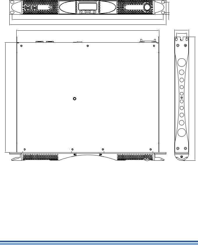
Mechanical drawings |
4 |
|
|
32.2 |
465 |
5.9 |
482 |
|
439 |
44 |
|
32 |
456 |
496 |
FIGURE 2: K2 and K3 mechanical drawings.
2 | K Series | User guide
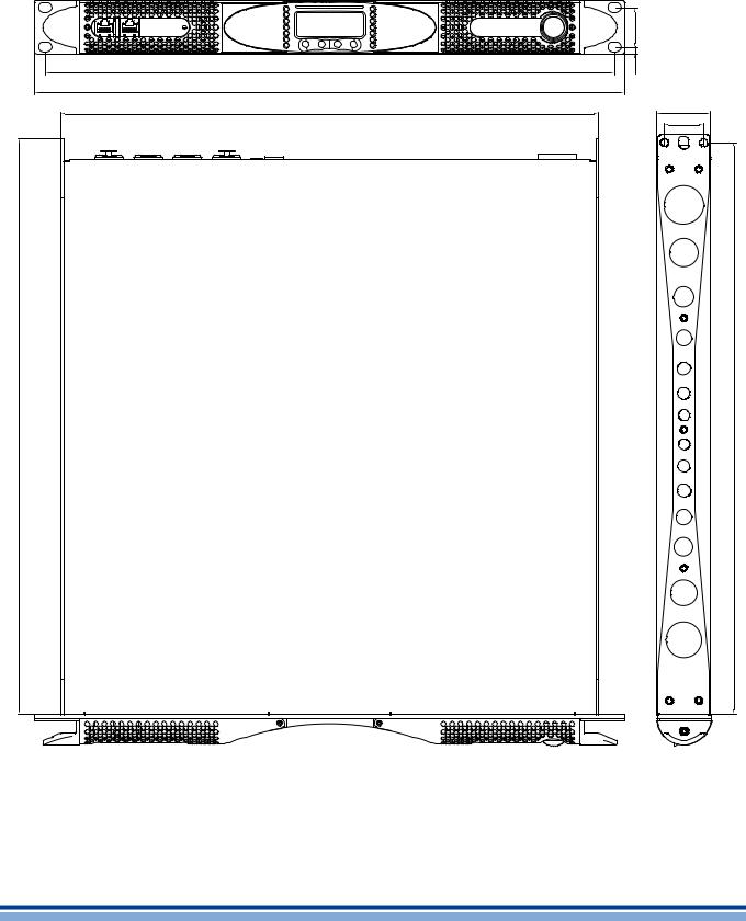
|
32.2 |
465 |
5.9 |
482 |
|
440 |
|
472.4
44 |
32 |
465.4 |
FIGURE 3: K6, K8, K10 and K20 mechanical drawings.
Mechanical drawings | 3

Front and rear panels |
5 |
|
A |
B |
C |
D |
E |
F |
G |
A. RJ45 plugs (either AESOP or RS485 ports |
D. Smart Card slot |
according to the amplifier configuration) |
E. Multifunction buttons |
B. LED bar: signal metering channel 1 |
F. LED bar: signal metering channel 2 |
C. Main display |
G. Main switch |
12 11
K2, K3 rear panel.
1 |
2 |
3 |
4 |
5 |
6 |
7 |
8 |
9 |
10 |
1.Mains plug
2.Air vents
3.Serial ID selector for the RS485 port (non AESOP version only)
4.RS485 serial port (non AESOP version only)
5.AES3/analog switch for input 2
6.Input 2: channel 2 analog input in analog mode or AES3 input in AES3 mode, according to the position of the switch in #5
7.Line output channel 2
8.Link button: link input from channels 1 and 2
9.Line output channel 1
10.Input 1: channel 1 analog input
11.Speaker connector: output channel 1
12.Speaker connector: output channel 2
13.Ethernet+AESOP ports (AESOP version only)
14.Vext: 12 VDC, 1A external voltage input (AESOP version only)
K2, K3 AESOP rear panel.
13 14
4 | K Series | User guide

10 9
K6, K8, K10, K20 rear panel.
1 |
2 |
3 |
4 |
5 |
6 |
7 |
8 |
1.Mains plug
2.Air vents
3.Serial ID selector for the RS485 port (non AESOP version only)
4.RS485 serial port (non AESOP version only)
5.AES3/analog switch for input 2
6.Input 2: channel 2 analog input in analog mode or AES3 input in AES3 mode, according to the position of the switch in #5
7.Link button: link input from channels 1 and 2
8.Input 1: channel 1 analog input
9.Speaker connector: output channel 1
10.Speaker connector: output channel 2
11.Ethernet+AESOP ports (AESOP version only)
12.Vext: 12 VDC, 1A external voltage input (AESOP version only)
K6, K8, K10, K20 AESOP rear panel.
11 12
Front and rear panels | 5
Installation |
6 |
|
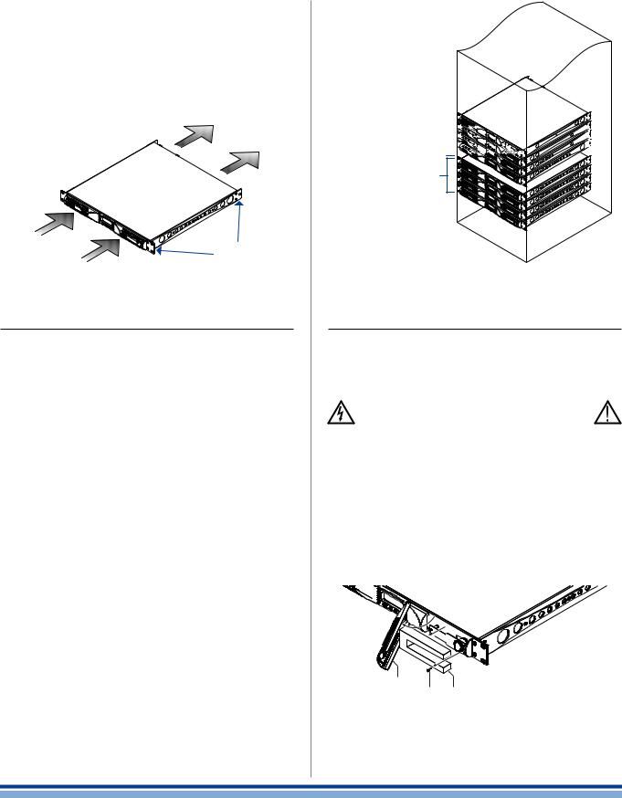
The common installation of the amplifier is in rack cabinets: in order to limit the risk of mechanical damages, the amplifiers must be fixed to the rack using both frontal and rear mounting brackets.
Note: Instead of connecting the amplifier to the power grid directly, plug the amplifier’s mains connections to a power distribution panel inside the rack cabinet.
Mounting
Brackets
FIGURE 4: Mounting brackets and air flow direction.
6:1.Cooling
Install the amplifier in a well-ventilated location: the ventilation openings must not be impeded by any item such as newspapers, tablecloths, curtains, etc; keep a distance of at least 50 cm from the front and rear ventilation openings of the amplifier.
All Powersoft amplifiers implement a forced-air cooling system to maintain low and constant operating temperatures. Drawn by the internal fans, air enters from the front panel and is forced over all components, exiting at the back of the amplifier.
The amplifier’s cooling system features “intelligent” var- iable-speed DC fans which are controlled by the heatsink temperature sensing circuits: the fans speed will increase only when the temperature detected by the sensors rises over carefully predetermined values. This ensures that fan noise and internal dust accumulation are kept to a strict minimum.
Should however the amplifier be subject to an extreme thermal load, the fan will force a very large volume of air through the heat sink. In the extremely rare event that the amplifier should dangerously overheat, sensing circuits shut down all channels until the amplifier cools down to a safe operating temperature. Normal operation is resumed automatically without the need for user intervention.
X Series amplifiers can be stacked one on top of the other due to the efficient cooling system they are equipped with.
There is however a safety limit to be observed: in case a rack with closed back panels is used, leave one rack unit empty every four installed amplifiers to guarantee adequate air flow.
1 unit space every 


 4 amp stacked into


 closed rack cabinet


4 amp stacked
FIGURE 5: How to stack the amplifiers in closed racks.
6:2.Cleaning
Always use a dry cloth for cleaning the chassis and the front panel. Air filter cleaning should be scheduled according to the dust levels in the amplifier’s operating environment.
Disconnect the AC main source before attempting to clean any part of the amplifier
In order to clean the vent filters you need to remove the front cover: never attempt to open any other part of the unit.
By means of a screwdriver Phillips PH1, unscrew the screws that lock the left and right cover grils on the front panel (ref. FIGURE 6), gently lift the covers and remove the filters. You may use compressed air to remove the dust from filters, or wash it with clean water: in the latter case ensure that the filters are dry before reassembly.
cover grill
screw lter
FIGURE 6: Cleaning air filters.
6 | K Series | User guide
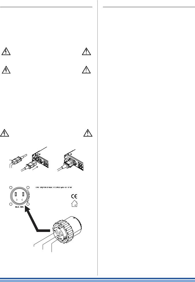
6:3.AC mains supply
The AC Main connection is made via the
ffAMP CPC 45A connector in K6, K8, K10 and K20;
ffIEC C20 connector in K3 and K2.
The FIGURE 7 shows how to connect the mains power cable to the amplifier.
Make sure the AC mains voltage used is within the acceptable operating voltage range: 115V-230V ±10%.
It is important to connect the ground for safety, do not use adapters that disable the ground connection.
All K Series amplifiers have an automatic power factor correction system – PFC – for a perfect mains network interface. The PFC minimizes the reactive power reflected on the network and reduces the harmonic distortion on the voltage/current waveform: in this way the amplifier is seen as a resistive load from the mains network. Furthermore, the system allows performance to be maintained even in case of varying mains voltage.
Connection to the mains shall be done only by a electrotechnical Skilled person according the national requirements of the countries where the unit is sold
A |
|
open the lock |
|
and insert the plug |
lock the plug |
ground |
|
mains |
|
B
|
|
|
|
|
|
|
|
|
|
|
|
|
|
|
|
|
|
|
|
|
|
|
|
|
|
|
|
|
|
|
|
|
|
|
|
|
|
|
|
|
|
|
|
|
|
|
|
|
|
|
|
|
|
|
|
|
|
|
|
|
|
|
|
|
|
|
|
|
|
|
|
|
|
|
|
|
|
|
|
|
|
|
|
|
|
|
|
|
|
|
|
|
|
|
|
|
|
|
|
|
|
|
|
|
|
|
|
|
|
|
|
|
|
|
|
|
|
|
|
|
|
|
|
|
|
|
|
|
|
|
|
|
|
|
|
|
|
|
|
|
|
|
|
|
|
|
|
|
|
|
|
|
|
|
|
|
|
|
|
|
|
|
|
|
|
|
|
|
|
|
|
|
|
|
|
|
|
|
|
|
|
|
|
|
|
|
|
|
|
|
|
|
|
|
|
|
|
|
|
|
|
|
|
|
|
|
|
|
|
|
|
|
|
|
|
|
|
|
|
|
|
|
|
|
|
|
|
|
|
|
|
|
|
|
|
|
|
|
|
|
|
|
|
|
|
|
|
|
|
|
|
|
|
|
|
|
|
|
|
|
|
|
|
|
|
|
|
|
|
|
|
|
|
|
|
|
|
|
|
|
|
2 |
|
1 |
|
3 |
|
|
|
|
|
|
|
|
|
|
|
|
|
|
|
|
|||||||
|
|
|
|
|
|
|
|
|
|
|
|
|
|
|
|
|
|
|
|
|
||||||||||
|
|
|
|
|
|
|
|
|
|
|
|
|
|
|
|
|
|
|
|
|
||||||||||
|
|
|
|
|
|
N |
|
|
|
|
|
|
|
|
|
|
|
|
|
|
|
|
|
|
|
|
|
|
|
|
|
|
|
|
|
|
Neutral |
|
L |
|
GND |
||||||||||||||||||||
|
|
|
|
|
|
|
|
Line |
|
|||||||||||||||||||||
|
|
|
|
|
|
|
|
|
|
|
|
Protective |
||||||||||||||||||
|
|
|
|
|
|
|
|
|
|
|
|
|
earth |
|||||||||||||||||
FIGURE 7: Mains connecors; A) IEC C20 in K2 and K3; B) AMP CPC 45A in K6, K8, K10 and K20.
6:4.Precautions regarding installation
Placing and using the amplifier for long periods of time on heat generating sources will affect its performance. Avoid placing the amplifier on heat generating sources. Install this amplifier as far as possible from tuners and TV sets. An amplifier installed in close proximity of such equipment may experience noise or generic performance degradation.
The power cord type provided with the amplifier are ffLAPP OLFLEX191 3G6 / SJT 3XAWG10
for K6, K8, K10 and K20.
ffBahoing SJT 3x16AWG or I-sheng SGIS 3G 1,5 mm2 for K3 - K2.
WARNING: TO PREVENT FIRE OR ELECTRIC SHOCK
ffThis device must be powered exclusively by earth connected mains sockets in electrical networks compliant to the IEC 364 or similar rules.
ffInstall K6, K8, K10 and K20 into rack cabinet.
ffWith K6, K8, K10 and K20 a sectioning breaker between the mains connections and the amplifier must be installed inside the rack cabinet. Suggested device is 32A/250VAC, C or D curve, 10kA.
ffWith K2 and K3 provide a sectioning breaker between the mains connections and the amplifier. Suggested device is 16A/250VAC, C or D curve, 10kA.
ffBefore powering this amplifier, verify that the correct voltage rating is being used.
ffVerify that your mains connection is capable of satisfying the power ratings of the device.
ffDo not use this amplifier if the electrical power cord is frayed or broken.
ffOutput terminals are hazardous: wiring connection to these terminals require installation by an instructed person and the use of ready made leads.
ffTake care to secure the output terminal before switching the device on.
ffTo avoid electrical shock, do not touch any exposed speaker wiring while the amplifier is operating.
ffDo not spill water or other liquids into or on the amplifier.
ffNo naked flame sources such as lighted candles should be placed on the amplifier.
ffDo not remove the cover. Failing to do so will expose you to potentially dangerous voltage.
ffIt is absolutely necessary to verify this fundamental requirement of safety and, in case of doubt, require an accurate check by qualified personnel.
ffThe manufacturer cannot be held responsible for damages caused to persons, things or data due to an improper or missing ground connection.
ffContact the authorized service center for ordinary and extraordinary maintenance.
Installation | 7
 Loading...