

Page 1

K Series
Top class amplification covering
any power needs in touring applications
K2, K3
K6, K8, K10, K20
and DSP + AESOP versions
©2014 Powersoft
DO000044.03 Rev 01
USER GUIDE
Keep this manual
for future reference
Page 2

powersoft_KSeries_uguide_en_v3.0
Data are subject to change without notice.
For latest update please refer to the
online version available on www.powersoft-audio.com.
Page 3

K Series User Guide
Table of contents
1. Important safety instructions iii
Importantes instructions de sécurité iv
Instrucciones de seguridad importantes v
Importanti istruzioni di sicurezza vi
2. Regulatory information vii
3. K Series 1
3 : 1.Welcome 1
3 : 2.Unpacking & checking for shipping damage 1
3 : 3.Disposal of the packing material 1
3 : 4.About the amplifier platform 1
3 : 4.1. More sound and less weight 1
3 : 4.2. The Show Always Goes On 1
4. Mechanical drawings 2
5. Front and rear panels 4
6. Installation 6
8. LEDs and display menu 11
8 : 1.LED chart 11
8 : 2.Front display 11
8 : 2.1. How to navigate the main menu 11
8 : 2.2. Me nu diag rams 12
9. Settings 15
9 : 1.Amplifier settings: Output attenuation 15
9 : 2.Amplifier settings: Input Gain/Sensitivity 15
9 : 3.Amplifier settings: Input select 15
9 : 4.Amplifier settings: Max output voltage 15
9 : 5.Amplifier settings: Max mains current 16
9 : 6.Amplifier settings: Clip limiter CH1/CH2 16
9 : 7.Amplifier settings: Gate CH1/CH2 16
9 : 8.Amplifier settings: Mute at power on 16
9 : 9.Amplifier settings: Idle mode 16
6 : 1.C ooling 6
6 : 2.Cleaning 6
6 : 3.AC mains supply 7
6 : 4.Precautions regarding installation 7
7. Connections 8
7 : 1.Signal grounding 8
7 : 2.Analog input 8
7 : 3.Analog line output 8
7 : 4.Digital Input 8
7 : 5.AESOP 9
7 : 6.Loudspeaker connections 9
7 : 6.1. B ridg e-ti ed load 9
7 : 6.2. In terna l signal path po larit y 10
7 : 7.V E xt 10
7 : 8.RS-485 connection 10
9 : 10.DSP Settings: Common settings 17
9 : 10.1. Source selec tion 17
9 : 10.2. AES 3 17
9 : 10.3. Cross limit 18
9 : 10.4. Sound sp eed (m/s) 18
9 : 11.DSP Settings: Channel settings 18
9 : 11.1. EQs 18
9 : 11. 2. L o- pas s/ Hi- pas s fil ter s 19
9 : 11. 3. Pol arit y 19
9 : 11. 4. Cha nnel Delay 19
9 : 11. 5. Ga in 19
9 : 11. 6. Limi ters 19
9 : 11.7. Damping Con tro l 22
9 : 12.DSP Settings: Channel setup 23
9 : 12.1. Auxiliary delay 23
9 : 12.2. Diagnos tic s 23
Table of contents | i
Page 4

9 : 13.DSP Settings: Input EQ 23
13. Setup 33
9 : 14.DSP Settings: Reset input section 23
9 : 15.DSP Settings: Reset output section 23
10. Network operations 24
10 : 1.Introduction to AESOP 24
10 : 1.1. Data s trea m 24
10 : 1.2. Audio 24
10 : 1.3. Ethernet int erna l swi tch 24
10 : 1.4. Forwarding and repeater modes 24
10 : 2.KAESOP repeater mode 25
10 : 3.KEASOP forward mode 26
10 : 3.1. For wa rd t o A ES 3- A 26
10 : 3.2. For ward to AES3 -B 26
10 : 3.3. Forwa rd to b oth 26
10 : 4.Network robustness 27
10 : 4.1. Daisy chain 27
10 : 4.2. Daisy chain with redundant AES3 27
10 : 4.3. Daisy chain with AES3 and Ethernet redundancy 28
10 : 4.4. Two degree redundant daisy chain 29
10 : 5.Network settings menu 30
11. Display 31
11 : 1.Display: Output meters 31
11 : 2 .Display: Temperature 31
11 : 3.Display: Mains meters 31
11 : 4.Display: Amplifier name 31
12. Local presets 32
12 : 1.Local preset: Locked presets 32
12 : 2.Local preset: Locked bank size 32
12 : 7.Setup: Hardware info 33
12 : 8.Setup: Hardware monitor 33
12 : 9.Set up; LCD contra st 33
12 : 10.Setup: Set the keylock code 33
12 : 11.Setup: Single channe muting 33
14. System and signal protections 34
13 : 1.Turn-On/ Turn-Off muting 34
13 : 2.Short circuit protec tion 34
13 : 3.Thermal protection 34
13 : 4.DC fault protection 34
13 : 5.Input/Output protection 34
15. SmartCard 35
15 : 1.Firmware update 35
15 : 2.Step-Up card 35
16. Software 36
16 : 1.Armonía Pro Audio Suite 36
16 : 1.1. Networ king 36
16 : 2.Third party soft ware 36
17. Warranty and assistance 37
17 : 1.Warranty 37
17 : 1.1. Product warranty 37
17 : 1.2. Return of Goods 37
17 : 1.3. Repair or repla cemen t 37
17 : 1.4. Cost and responsibility of transport 37
17 : 2.Assistance 37
18. Specifications 38
12 : 3.Local preset: Recall local preset 32
12 : 4.Local preset:Save local preset 32
12 : 4.1. Save to an empty slot 32
12 : 4.2. Overw riti ng an existing pre set 32
12 : 5.Local preset: Change lock code 32
12 : 6.Local preset: Erase all presets 32
ii | K Series | User guide
Page 5
Important safety instructions
1
EXPLANATIONS OF GRAPHICAL SYMBOLS
The triangle with the lightning bolt is used to alert the
user to the risk of electric shock.
The triangle with the exclamation point is used to
alert the user to important operating or maintenance
instructions.
The CE-mark indicates the compliance with the low
voltage and electromagnetic compatibility.
Symbol for earth/ground connection.
Symbol indicating that the equipment is for indoor
use only.
Symbol for conformity with Directive 2002/96/EC
and Directive 2003/108/EC of the European
Parliament on waste electrical and electronic equipment (WEEE).
WARNING: TO REDUCE THE RISK OF ELECTRIC SHOCK, DO
NOT ATTEMPT TO OPEN ANY PART OF THE UNIT. NO USERSERVICEABLE PARTS INSIDE. REFER SERVICING TO QUALIFIED
SERVICE PERSONNEL.
TO COMPLETELY DISCONNECT THIS APPARATUS FROM THE
AC MAINS, DISCONNECT THE POWER SUPPLY CORD PLUG
FROM THE AC RECEPTACLE.*
THE MAINS PLUG OF THE POWER SUPPLY CORD MUST
REMAIN READILY ACCESSIBLE.**
DO NOT EXPOSE THIS EQUIPMENT TO RAIN OR MOISTURE,
DRIPPING OR SPLASHING LIQUIDS. OBJECTS FILLED WITH
LIQUIDS, SUCH AS VASES, SHOULD NOT BE PLACED ON THIS
APPARATUS.
K6, K8, K10 AND K20 MUST BE INSTALLED IN RACK CABINETS:
INSTEAD OF CONNECTING THE AMPLIFIER TO THE POWER
GRID DIRECTLY, PLUG THE AMPLIFIER’S MAINS CONNECTIONS VIA A
SECTIONING BREAKER TO A POWER DISTRIBUTION PANEL INSIDE THE
RACK CA BINET.
WHEN THE UNIT IS INSTALLED IN A CABINET OR A SHELF,
MAKE SURE THAT IT HAS SUFFICIENT SPACE ON ALL SIDES TO
ALLOW FOR PROPER VENTILATION (50 CM FROM THE FRONT AND
REAR VENTILATION OPENINGS).
CONNECTION TO THE MAINS SHALL BE DONE ONLY BY A
ELECTROTECHNICAL SKILLED PERSON ACCORDING THE
NATIONAL REQUIREMENTS OF THE COUNTRIES WHERE THE UNIT IS SOLD.
CAUTION
RISK OF ELECTRICK SHOCK
DO NOT OPEN
Electrical energy can perform many useful functions. This unit has
been engineered and manufactured to ensure your personal safety. But
IMPROPER USE CAN RESULT IN POTENTIAL ELECTRICAL SHOCK OR
FIRE HAZARD.
In order not to defeat the safeguards incorporated into this product,
observe the following basic rules for its installation, use and service.
Please read these “Important Safeguards” carefully before use.
Important safety instructions
1. Read these instructions.
2. Keep these instructions.
3. Heed all warnings.
4. Follow all instructions.
5. Do not use this equipment near water.
6. Clean only with a dry cloth.
7. Do not block any ventilation openings. Install in accordance with
the manufacturer’s instructions.
8. Do not install near any heat sources such as radiators, heat registers,
stoves, or other apparatus (including amplifiers) that produce heat.
9. Do not defeat the safety purpose of the polarized or groundingtype plug. A polarized plug has two blades with one wider than the
other. A grounding type plug has two blades and a third grounding
prong. The wide blade or the third prong are provided for your
safety. If the provided plug does not fit into your outlet, consult an
electrician for replacement of the obsolete outlet.
10. Protect the power cord from being walked on or pinched particularly at plugs, convenience receptacles, and the point where they
exit from the apparatus.
11. Only use attachments/accessories specified by the manufacturer.
12. Use only with the cart, stand, tripod, bracket, or table specified by
the manufacturer, or sold with the apparatus. When a
cart is used, use caution when moving the cart/apparatus combination to avoid injury from tip-over.
13. Unplug this apparatus during lightning storms or
when unused for long periods of time.
14. Refer all servicing to qualified service personnel. Servicing is
required when the apparatus has been damaged in any way, such
as power-supply cord or plug is damaged, liquid has been spilled
or objects have fallen into the apparatus, the apparatus has been
exposed to rain or moisture, does not operate normally, or has
been dropped.
Numbers 9 and 13 apply only to K2 and K3.
* K6, K8, K10 and K20: interrupt the mains by switching the sectioning
breaker off.
** Valid for K2 and K3 model only; with K6, K8, K10 and K20 a free leads
power cord (i.e. without plug) is provided: this solution is intended for connecting the device to a sectioning breaker on the mains. Refer to the installation instruction for selecting the proper sectioning breaker.
Important safety instructions | iii
Page 6

Importantes instructions
de sécurité
AVIS
RISQUES D’ÉLECTROCUTION
NE PAS OUVRIR
EXPLICATION DES SYMBOLES GRAPHIQUES
La triangle avec le symbol du foudre est employée
pour alerter l’utilisateur au risque de décharge électrique.
Le triangle avec un point d’exclamation est employée
pour alerter l’utilisateur d’instruction importantes
pour lors opérations de maintenance.
Le marquage CE indique la conformité à la directive de
basse tension et la compatibilité électromagnétique.
Symbole pour la connexion à la terre.
Symbole indiquant que l’équipement est destiné à
l’emploi à l’intérieur.
Symbole pour la conformité al la Directive 2002/96/
EC et la Directive 2003/108/EC du Parlement
Européen sur les équipements électriques et électroniques (WEEE).
MISE EN GARDE : AFIN DE RÉDUIRE LES RISQUES DE CHOC
ÉLECTRIQUE, N’ESSAYEZ PAS D’OUVRIR L’UNITÉ, MEME EN
PARTIE. AUCUNE PIÈCE A L’INTERIEUR NE PEUT ETRE CHANGÉE PAR
L’UTILISATEUR. LAISSEZ L’ENTRETIEN A UN PERSONNEL QUALIFIÉ.
POUR INTERROMPRE COMPLÈTEMENT L’ALIMENTATION
ÉLECTRIQUE DE L’UNITÉ, DÉBRANCHEZ LE CORDON
D’ALIMENTATION DE LA PRISE DE COURANT.*
LES FICHES DU CORDON D’ALIMENTATION DOIVENT RESTER
ACCESSIBLES A TOUT MOMENT.**
AFIN DE RÉDUIRE LES RISQUES D’INCENDIE ET
D’ÉLECTROCUTION, N’EXPOSEZ PAS CET APPAREIL À LA
PLUIE OU À L’HUMIDITÉ. L’UNITÉ NE DOIT JAMAIS ÊTRE EXPOSÉ AUX
ÉCLABOUSSURES, AU DÉVERSEMENT OU À L’ÉGOUTTEMENT DE
LIQUIDES, QUELS QU’ILS SOIENT.
K6, K8, K10 ET K20 DOIT ÊTRE INSTALLÉ DANS UN RACK
ARMOIRE : AU LIEU DE CONNECTER L’AMPLIFICATEUR POUR
LE RÉSEAU ÉLECTRIQUE DIRECTEMENT, BRANCHEZ LA FICHE DE
L’AMPLIFICATEUR VIA LE DISJONCTEUR AUX PANNEAU DE
DISTRIBUTION ÉLECTRIQUE À L’INTÉRIEUR DE L’ARMOIRE.
L’énergie é lectrique peut remplir beaucoup de fonctions utiles. Cet appareil a été conçu et fabriqué pour assurer votre propre sécurité. Mais UNE
UTILISATION INCORRECTE PEUT ENTRAÎNER UN RISQUE POTENTIEL
D’ÉLECTROCUTION OU D’INCENDIE. Afin de ne pas annuler les dispositifs de
sécurité incorporés dans cet appareil, observez les règles fondamentales suivantes pour son installation, son utilisation et sa réparation. Veuillez lire attentivement ces “Importantes mesures de sécurité” avant d’utiliser l’appareil.
Importantes instructions de sécurité
1. Lisez les directives suivantes.
2. Conservez ces directives.
3. Observez et respectez tous les avertissements.
4. Suivez toutes les directives.
5. N’utilisez pas cet appareil près de l’eau.
6. Nettoyez cet appareil uniquement avec un chiffon sec.
7. Ne bouchez pas les fentes de ventilation. Respectez les directives
du fabricant pour l’installation de l’appareil.
8. N’installez pas l’appareil à proximité d’une source de chaleur telle
qu’un radiateur, une bouche d’air chaud, une cuisinière ou tout autre appareil (y compris des amplificateurs) émettant de la chaleur.
9. Ne désactivez pas le dispositif de sécurité appliqué à la fiche
polarisée ou à la fiche avec mise à la terre. Une fiche polarisée est
équipée de deux lames dont l’une est plus large que l’autre. Une
fiche avec mise à la terre est équipée de deux lames et une broche
destinée à la mise à la terre. La lame la plus large et la troisième
broche sont des dispositifs de sécurité. Si vous ne réussissez pas
à brancher la fiche fournie dans la prise de courant, consultez un
électricien et faites remplacer la prise par une neuve.
10. Ne placez pas le cordon d’alimentation dans des endroits passants
et assurezvous qu’il ne peut pas être pincé, surtout au niveau des
fiches, de la prise de courant et à l’endroit où il sort de l’appareil.
11. Utilisez uniquement les éléments de raccordement et les accessoires recommandés par le fabricant.
12. Utilisez l’appareil uniquement avec le chariot, le trépied, le support
ou la table recommandés par le fabricant ou achetés
avec l’appareil. Lorsque vous utilisez un chariot,
prenez des précautions en déplaçant le chariot et
l’appareil afin dene pas les renverser, ce qui pourrait
entraîner des blessures.
13. Débranchez cet appareil en cas d’orage ou lorsque vous ne
l’utilisez pas pendant de longues périodes.
14. Pour toute réparation, adressez-vous à un réparateur qualifié.
Faites réparer l’appareil s’il a été endommagé de quelque manière
que ce soit, par exemple si le cordon d’alimentation ou sa fiche
sont endommagés, si du liquide ou tout autre corps étranger a
pénétré dans l’appareil, si l’appareil a été exposé à la pluie ou à
l’humidité, s’il ne fonctionne pas normalement ou s’il est tombé.
QUAND L’UNITÉ EST INSTELLÉ DANS UNE ARMOIRE OU UNE
ÉTAGÈRE, ASSUREZ-VOUS QU’IL Y À UN ESPACE SUFFISANT
TOUT AUTOUR POUR PERMETTRE UNE BONNE VENTILATION (50 CM
DES ORIFICES DE VENTILATION AVANT ET ARRIÈRE).
iv | K Series | User guide
Numéros 9 et 13 ne s'appliquent qu'aux K2 et K3.
* K6, K8, K10 and K20: interrompre le réseau par commutation de le disjoncteur.
** Valable seulement pour le K2 et K3 modèles; on fournis avec K6, K8, K10
et K20 un cordon avec fils libres (c’est à dire sans fiche) : cette solution
est destinée à connecter l’appareil à un disjoncteur sur le réseau. Se
référer aux instructions d’installation pour sélectionner le disjoncteur de
sectionnement approprié.
Page 7
Instrucciones de seguridad
importantes
PRECAUCIÓN
RIESGO DE CHOQUE ELÉCTRICO
NO ABRA LA UNIDAD
EXPLICACIÓN DE LOS SÍMBOLOS GRÁFICOS
El triángulo con el símbolo de rayo eléctrico es usa-
do para alertar al usuario de el riesgo de un choque
eléctrico.
El triángulo con el signo de admiración es usado
para alertar al usuario de instrucciones importantes
de operación o mantenimiento.
La marca CE indica el cumplimiento de la directiva
de bajo voltaje y de compatibilidad electromagnética.
Símbolo de la conexión a tierra.
Símbolo que indica que el equipo es sólo para uso
en interiores.
Símbolo de conformidad con la Directiva 2002/96/
EC y Directiva 2003/108/EC del Parlamento Europeo
sobre los aparatos eléctricos y electrónicos (WEEE).
PRECAUCIÓN: PARA REDUCIR EL RIESGO DE DESCARGA
ELÉCTRICA, NO DESMONTE LA TAPA (NI EL PANEL TRASERO).
NO HAY PIEZAS REPARABLES POR EL USUARIO EN EL INTERIOR.
LLÉVELO A REPARAR A PERSONAL DE SERVICIO CUALIFICADO.
PARA DESCONECTAR COMPLETAMENTE EL APARATO, EL
ENCHUFE DEL CABLE DE ALIMENTACIÓN DE LA UNIDAD
DEBERÁ SER RETIRADO DE LA TOMA DE CORRIENTE.*
EL ENCHUFE DEL CABLE DE ALIMENTACIÓN DEBERÁ
PERMANECER FÁCILMENTE ACCESIBLE.**
NO EXPONGA ESTE UNITAD A LA LLUVIA O LA HUMEDAD,
GOTEO O SALPICADURAS. NO COLOQUE OBJETOS LLENOS DE
LÍQUIDOS, TALES COMO VASIJAS, SOBRE EL APARATO.
K6, K8, K10 Y K20 SE DEBEN INSTALAR EN ARMARIOS RACK:
EN LUGAR DE CONECTAR EL AMPLIFICADOR A LA RED
ELÉCTRICA DIRECTAMENTE, CONECTE LAS CONEXIONES DE RED DEL
AMPLIFICADOR A TRAVÉS DE UN INTERRUPTOR DE SECCIONAMIENTO
A UN PANEL DE DISTRIBUCIÓN DE ENERGÍA EN EL INTERIOR DEL
ARMARIO RACK.
CUANDO LA UNIDAD SE INSTALA EN UN ARMARIO O UN
ESTANTE, ASEGÚRESE QUE TENGA SUFICIENTE ESPACIO EN
TODOS LOS LADOS PARA PERMITIR LA VENTILACIÓN ADECUADA
(50 CM DE LOS ORIFICIOS DE VENTILACIÓN DELANTEROS Y
TRASEROS).
La energìa eléctrica puede realizar numerosas funciones útiles. Esta unidad ha sido diseñada y fabricada para brindarle un funcuionamento seguro. Sin embargo, el USO INCORRECTO O PUEDE PRODUCIR INCENDIOS
O DESCARGAS ELÉCTRICAS. Para no anular las salvaguardas incorporadas a este producto, asegúrese de respetar las reglas básicas siguientes para su instalacíon, uso y servicio. Por favor lea atentamente
estas “Salvaguardas importantes” ante del uso.
Instrucciones de seguridad importantes
1. Lea estas instrucciones.
2. Guarde estas instrucciones.
3. Respete todas las advertencias.
4. Siga todas las instrucciones.
5. No utilice este aparato cerca del agua.
6. Límpielo únicamente con un paño seco.
7. No bloquee los orificios de ventilación. Instale el aparato según las
instrucciones del fabricante.
8. No lo instale cerca de fuentes de calor como radiadores, calefactores, hornos u otros aparatos (incluidos los amplificadores) que
generen calor.
9. Respete la finalidad de seguridad del enchufe polarizado o de tipo
conexión a tierra. Un enchufe polarizado presenta dos contactos,
uno más ancho que el otro. Un enchufe de tipo conexión a tierra
dispone de dos contactos y una tercera clavija de conexión a tierra.
El contacto ancho o la tercera clavija se suministra para su seguridad. Si el enchufe suministrado no encaja en la toma de corriente,
póngase en contacto con un electricista para el reemplazo del
tomacorriente que quedó obsoleto.
10. Para proteger el cable de alimentación, aléjelo de lugares de paso
o donde pueda ser aplastado, especialmente en la punta de los
enchufes, los tomacorrientes o el punto donde el cable sale del
aparato.
11. Utilice únicamente los complementos o accesorios especificados
por el fabricante.
12. Utilícelo únicamente con el carro, pedestal, trípode, abrazadera o
mesa especificados por el fabricante o vendidos con
el aparato. Si utiliza un carro, tenga cuidado al moverlo junto con el aparato para evitar lesiones en el
caso de una caída.
13. Desenchufe el aparato durante tormentas eléctricas o cuando no
se utilice durante períodos de tiempo prolongados.
14. Solicite servicio técnico únicamente a personal de servicio técnico
especializado. Será necesario solicitar servicio técnico si el aparato
ha sufrido daños como, por ejemplo, si el cable de alimentación o
el enchufe están dañados, se ha vertido líquido o se ha caído algún
objeto dentro del aparato, o bien si dicho aparato ha sido expuesto a
la lluvia o a humedad, no funciona correctamente o se ha caído.
Números 9 y 13 se aplican sólo a K2 y K3.
* K6, K8, K10 and K20: interrumpir la red apagando el disyuntor de la red.
** Válido para los modelos K3 y K3 sólo; con K6, K8, K10 and K20 se
proporciona un cable de alimentación de hilos libres (es decir, sin enchufe):
se provee esta solución para conectar el dispositivo a un disyuntor en la
red. Consulte las instrucciones de instalación para seleccionar el disyuntor
impecables.
Table of contents | v
Page 8

Importanti istruzioni
di sicurezza
ATTENZIONE
RISCHIO DI SCOSSE
ELETTRICHE, NON APRIRE
SPIEGAZIONE DEI SIMBOLI GRAFICI
Il triangolo con il lampo è utilizzato per avvisare
l’utente del rischio di scossa elettrica.
Il triangolo con il punto esclamativo è utilizzato per
avvisare l’utente di importanti istruzioni d’uso e manutenzione.
The CE-mark indicates the compliance with the low
voltage and electromagnetic compatibility.
Simbolo della connessine di terra.
Simbolo che indica che l’apparecchio è solo per uso
interno.
Simbolo di conformità alla Direttiva 2002/96/CE e
alla Direttiva 2003/108/CE del Parlamento Europeo
sulle apparecchiature elettriche ed elettroniche
(RAEE).
ATTENZIONE: PER RIDURRE IL RISCHIO DI SCOSSE
ELETTRICHE, NON TENTARE DI APRIRE ALCUNA PARTE
DELL’UNITÀ. NON CI SONO PARTI INTERNE AD USO DELL’UTENTE.
RIVOLGERSI A PERSONALE QUALIFICATO PER L’ASSISTENZA.
PER SCOLLEGARE COMPLETAMENTE QUESTO APPARECCHIO
DALL’ALIMENTAZIONE PRINCIPALE, SCOLLEGARE LA SPINA
DEL CAVO DI ALIMENTAZIONE DALLA PRESA.*
LA SPINA DEL CAVO DI ALIMENTAZIONE DI RETE DEVE ESSERE
SEMPRE ACCESSIBILE.**
NON ESPORRE QUESTO APPARECCHIO ALLA PIOGGIA,
UMIDITÀ O SOSTANZE LIQUIDE. OGGETTI PIENI DI LIQUIDI,
COME VASI, NON DEVONO ESSERE COLLOCATI SU QUESTO APPARATO.
K6, K8, K10 E K20 DEVONO ESSERE INSTALLATI IN ARMADI
RAC K: INV ECE DI COLL EGAR E DIRET TAMENTE L’AMPLIFI CATORE
ALLA RETE ELETTRICA, COLLEGARE IL CAVO DI ALIMENTAZIONE
DELL’AM-PLIFICATORE AD UN INTERRUTTORE DI SEZIONAMENTO IN
UN PANNELLO DI DISTRIBUZIONE ALL’INTERNO DELL’ARMADIO RACK.
QUANDO L’UNITÀ È INSTALLATA IN UN MOBILE O SU UNO
SCAFFALE, ASSICURARSI CHE RIMANGA SPAZIO SUFFICIENTE
SU TUTTI I LATI PER CONSENTIRE UN’ADEGUATA VENTILAZIONE
(50 CM DAI FORI DI VENTILAZIONE ANTERIORI E POSTERIORI).
L’elettricità viene usata per svolgere molte funzioni utili, ma può anche
causare danni personali o agli oggetti se applicata in modo improprio.
Questo prodotto è stato progettato e realizzato con la massima attenzione alla sicurezza. Tuttavia, UN USO IMPROPRIO PUÒ PRODURRE
SCOSSE ELETTRICHE E/O INCENDI. Per evitare potenziali pericoli, osservare le seguenti istruzioni durante l’installazione, l’utilizzo e la pulizia
del prodotto. Per garantire la sicurezza e prolungare la vita utile del
monitor LCD, leggere attentamente le seguenti precauzioni prima di
usare il prodotto.
Importanti istruzioni di sicurezza
1. Leggere queste istruzioni.
2. Conservare le istruzioni.
3. Tenere conto di tutti gli avvisi.
4. Seguire tutte le istruzioni.
5. Non usare l'apparecchio in prossimità di acqua.
6. Pulire solo con un panno asciutto.
7. Non ostruire le prese di ventilazione. Installare secondo le indicazioni del produttore.
8. Non installare vicino a fonti di calore quali radiatori, bocchette
dell'aria calda, stufe o altri apparecchi (compresi gli amplificatori)
che producono calore.
9. Non compromettere la sicurezza delle spine polarizzate o con
messa a terra. Una spina polarizzata ha due terminali, di cui uno
più grande dell'altro. Una spina con messa a terra ha tre terminali,
di cui uno per la messa a terra. Il terminale più grande o il terzo
terminale ha una funzione di sicurezza. Se la spina in dotazione
non è adatta alla presa, far sostituire tale presa obsoleta da un
elettricista.
10. Evitare di calpestare o di schiacciare il cavo di alimentazione,
in particolare in corrispondenza di spine, prese della corrente e
punto di uscita dall'apparecchio.
11. Usare solo accessori specificati dal produttore.
12. Usare solo con il supporto indicato dal produttore (carrello, piedistallo, cavalletto, staffa o tavolo) o venduto con
l'apparecchio. Se si usa il carrello, fare attenzione
durante il trasporto dell'apparecchio sul carrello per
evitare danni causati dal ribaltamento.
13. Scollegare l'apparecchio dalla presa di corrente durante i temporali o se inutilizzato per lunghi periodi di tempo.
14. Ricorrere a personale qualificato per qualsiasi intervento. Tali
interventi sono necessari in caso di guasti dell'apparecchio
quali danneggiamento del cavo di alimentazione o della spina,
versamento di liquidi o caduta di oggetti nell'apparecchio, esposizione a pioggia o umidità o se l'apparecchio non funziona
normalmente o è caduto
I numeri 9 e 13 si applicano solo a K2 e K3.
* K6, K8, K10 e K20: interrompere l’alimentazione elettrica commutando
l’interruttore di sezionamento.
** Valido solo per i modelli K2 e K3; con K6, K8, K10 e K20 è fornito un cavo
di alimentazione con i terminali liberi (cioè senza spina): questa soluzione è
pensata per il collegamento diretto all’interruttore di sezionamento di rete.
Fare riferimento al manuale per le istruzioni di installazione e il corretto
dimensionamento dell’interruttore.
vi | K Series | User guide
Page 9
Regulatory information
2
FCC COMPLIANCE NOTICE
This device complies with part 15 of the FCC rules. Operation is subject
to the following two conditions: (1) This device may not cause harmful
interference, and (2) this device must accept any interference received,
including interference that may cause undesired operation.
CAUTION: Changes or modifications not expressly approved by the party
responsible for compliance could void the user’s authority to operate the
equipment.
NOTE: This equipment has been tested and found to comply with the
limits for a Class B digital device, pursuant to part 15 of the FCC Rules.
These limits are designed to provide reasonable protection against
harmful interference in a residential installation. This equipment generates, uses, and can radiate radio frequency energy and, if not installed
and used in accordance with the instruction manual, may cause harmful
interference to radio communications. However, there is no guarantee
that interference will not occur in a particular installation. If this equipment does cause harmful interference to radio or television reception,
which can be determined by turning the equipment off and on, the user
is encouraged to try to correct the interference by one or more of the
following measures:
Reorient or relocate the receiving antenna.
Increase the separation between the equipment and receiver.
Connect the equipment into an outlet on a circuit different from
that to which the receiver is connected.
Consult the dealer or an experienced radio/TV technician for help.
WEEE DIRECTIVE
If the time arises to throw away your product, please recycle all the components possible.
This symbol indicates that when the end-user wishes
to discard this product, it must be sent to separate collection facilities for recovery and recycling. By separating this product from other household-type waste, the
volume of waste sent to incinerators or land-fills will be
reduced and natural resources will thus be conserved.
EC DECLARATION OF CONFORMITY
Manufacturer:
Powersoft S.p.A.
via E. Conti 5
50018 Scandicci (Fi)
Italy
We declare that under our sole responsibility the products:
Model Names: K2, K3, K6, K8, K10, K20
K2 DSP+AESOP, K3 DSP+AESOP,
K6 DSP+AESOP, K8 DSP+AESOP, K10 DSP+AESOP,
K20 DSP+AESOP.
Intended use: Professional Audio Amplifier
Are in conformity with the provisions of the following EC Directives,
including all amendments, and with national legislation implementing
these directives:
2006/95/EC Low Voltage Directive
2004/108/EC Electromagnetic Compatibility Directive
2002/95/CE RoHs Directive
The following armonized standards are applied:
EN 55103-1:2009 /A1:2012
EN 55014-1:2006 /A1:2009 /A2:2011
EN 55022:2010 /AC:2011
EN 61000-3-2:2006 /A1:2009 /A2: 2009
EN 61000-3-3:2013
EN 61000-3-11:2000
EN 61000-3-12:2011
EN 55103-2:2009 /IS:2012
EN 61000-4-2:2009
EN 61000-4-3:2006 /A1:2008 /IS1:2009 /A2:2010
EN 61000-4-4:2012
EN 61000-4-5:2006
EN 61000-4-6:2014
EN 61000-4-11:2004
EN 60065:2002 /A1:2006 /A11:2008 /A2:2010 /A12:2011
The Waste Electrical and Electronic Equipment Directive (WEEE Directive)
aims to minimise the impact of electrical and electronic goods on the environment. Powersoft S.p.A. comply with the Directive 2002/96/EC and
2003/108/EC of the European Parliament on waste electrical finance the
cost of treatment and recovery of electronic equipment (WEEE) in order
to reduce the amount of WEEE that is being disposed of in land-fill site.
All of our products are marked with the WEEE symbol; this indicates that
this product must NOT be disposed of with other waste. Instead it is the
user’s responsibility to dispose of their waste electrical and electronic
equipment by handing it over to an approved reprocessor, or by returning it to Powesoft S.p.A. for reprocessing. For more information about
where you can send your waste equipment for recycling, please contact
Powesoft S.p.a. or one of your local distributors.
Scandicci,
15 July 2014
Luca Lastrucci
Managing Director
For compliance questions only: compliance@powersoft.it
Regulatory information | vii
Page 10

viii | K Series | User guide
Page intentionally left blank
Page 11

K Series User Guide
3
3 : 1.Welcome
Congratulations on buying a Powersoft K Series amplier!
We know you are eager to use your new amplier, but
please take a moment to read this user’s manual and safety
instructions. In case you have any questions, please do not
hesitate to contact your dealer or Powersoft.
Powersoft is a leading company in the eld of high
efciency audio power management. The Powersoft
switching mode technology has changed the way the
world looks at professional audio amplication: no other
amplier’s performance comes close for applications
demanding high power and long term reliability. Thanks
to amazing reductions in heat output and weight, without
sacricing output powers, Powersoft ampliers can be
used in an unlimited range of PA applications such as opera
houses, theaters, churches, cinema, and theme parks.
3 : 2.Unpacking & checking for shipping damage
Your Powersoft product has been completely tested and
inspected before leaving the factory. Carefully inspect the
shipping package before opening it, and then immediately
inspect your new product. If you nd any damage notify the
shipping company immediately.
The box contains the following:
One K Series amplier.
One AC mains power cord
This user guide.
3 : 3.Disposal of the packing material
The transport and protective packing has been selected
from materials which are environmentally friendly for disposal and can normally be recycled.
Rather than just throwing these materials away,
please ensure they are offered for recycling.
Amplier
3 : 4.About the amplifier platform
K Series has many advanced features, digital control
of many parameters, adjustable maximum m ains consumption, selectable digital presets and a graphic display
that shows detailed information of the status of the amplier. All K Series ampliers come with built in Power Factor
Correction. This unique feature ensures that a predominantly
resistive load is presented to mains thus minimizing current
distortion and voltage/current displacement. This leads to
improved performance of the amplier at high levels of output and avoids mains-voltage collapses, typical of standard
and switching power supplies. Another great advantage of
this technology is that its performance is, to a large extent,
independent of mains voltage. The rated output power does
not vary with load/line conditions.
3 : 4.1. More sound and less weight
Class D technology based ampliers are highly efcient,
delivering greater power to speakers with reduced heat dissipation: typical running efciency of output stages is 95%,
with only 5% of input energy dissipated as heat. This allows
for smaller dimensions, weight and power consumptions.
Contrary to conventional ampliers which achieve highest efciency only at full rated power output, Class D efciency is almost independent of output level. Music has an
average power density of 40% of its peak value; this means
that other (non-class D) ampliers can easily generate 10
times more heat than Powersoft products for the same
sound pressure level.
Powersoft ampliers deliver crystal-clear highs, and a
tight, well-dened low end: the most accurate reproduction
of an audio signal. Solid time proven design features ensure
extremely high performance in terms of super low total harmonic distortion, optimal frequency response, high power
bandwidth and damping factor across a vast number of application scenarios. Powersoft’s multi patented application
of Pulse Width Modulation (PWM) high frequency sampling
techniques is just one of the many factors contributing to
the K Series’ high performance ratings across the audio
bandwidth.
User guide
FIGURE 1: Packaging.
Mains cable
3 : 4.2. The Show Always Goes On
The K series offers complete protection against any
possible operation error. Every amplier in this series is
designed to work under a large range of possible conditions, delivering maximum power with maximum safety and
an outstanding long term reliability. Anticipating potential
problems at the design stage means your show always
goes on!
K Series | 1
Page 12
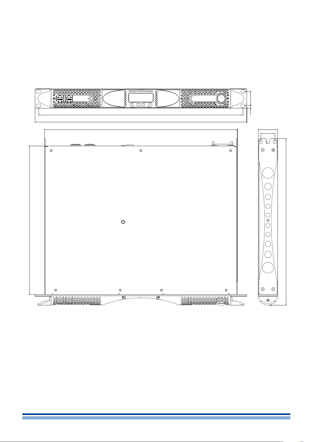
Mechanical drawings
4
32.2
456
465
482
439 44
5.9
32
496
2 | K Series | User guide
FIGURE 2: K2 and K3 mechanical drawings.
Page 13
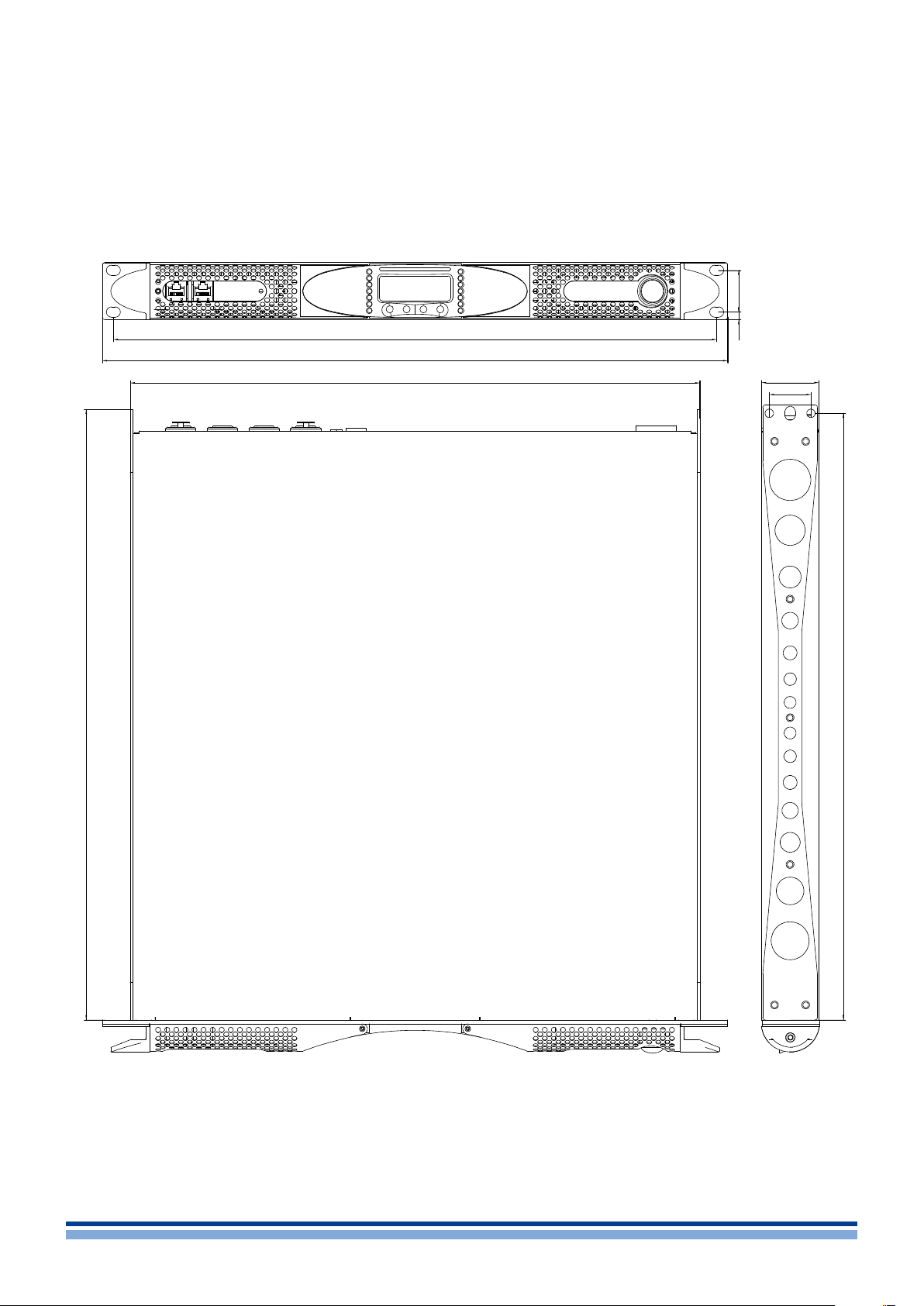
32.2
472.4
465
482
440 44
5.9
32
465.4
FIGURE 3: K6, K8, K10 and K20 mechanical drawings.
Mechanical drawings | 3
Page 14
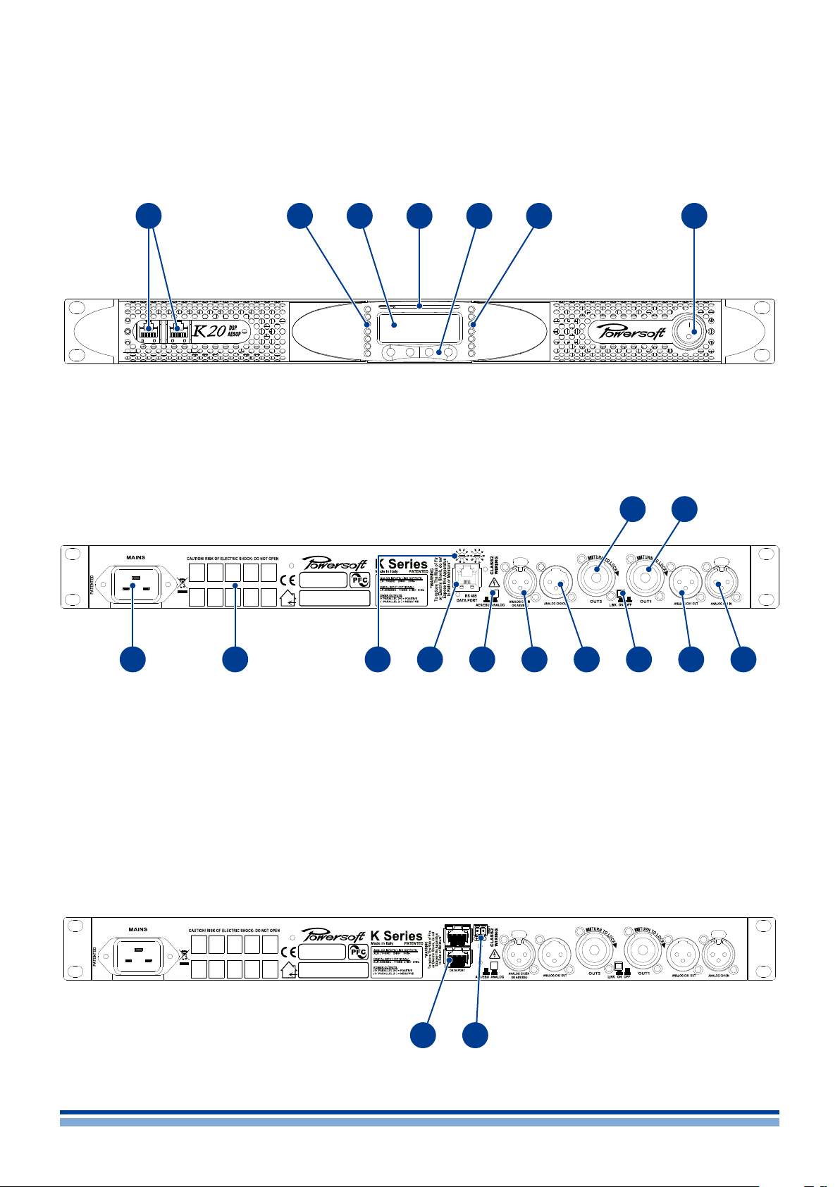
Front and rear panels
5
A
A. RJ45 plugs (either AESOP or RS485 ports
according to the amplier conguration)
B. LED bar: signal metering channel 1
C. Main display
K2, K3 rear panel.
B
C
D
E
D. Smart Card slot
E. Multifunction buttons
F. LED bar: signal metering channel 2
G. Main switch
F
12
G
11
1 2
1. Mains plug
2. Air vents
3. Serial ID selector for the RS485 port
(non AESOP version only)
4. RS485 serial port (non AESOP version only)
5. AES3/analog switch for input 2
6. Input 2: channel 2 analog input in analog
mode or AES3 input in AES3 mode, according
to the position of the switch in #5
K2, K3 AESOP rear panel.
3 5
4
7. Line output channel 2
8. Link button: link input from channels 1 and 2
9. Line output channel 1
10. Input 1: channel 1 analog input
11. Speaker connector: output channel 1
12. Speaker connector: output channel 2
13. Ethernet+AESOP ports (AESOP version only)
14. Vext: 12 V
version only)
13
14
6
, 1A external voltage input (AESOP
DC
7
8
9
10
4 | K Series | User guide
Page 15
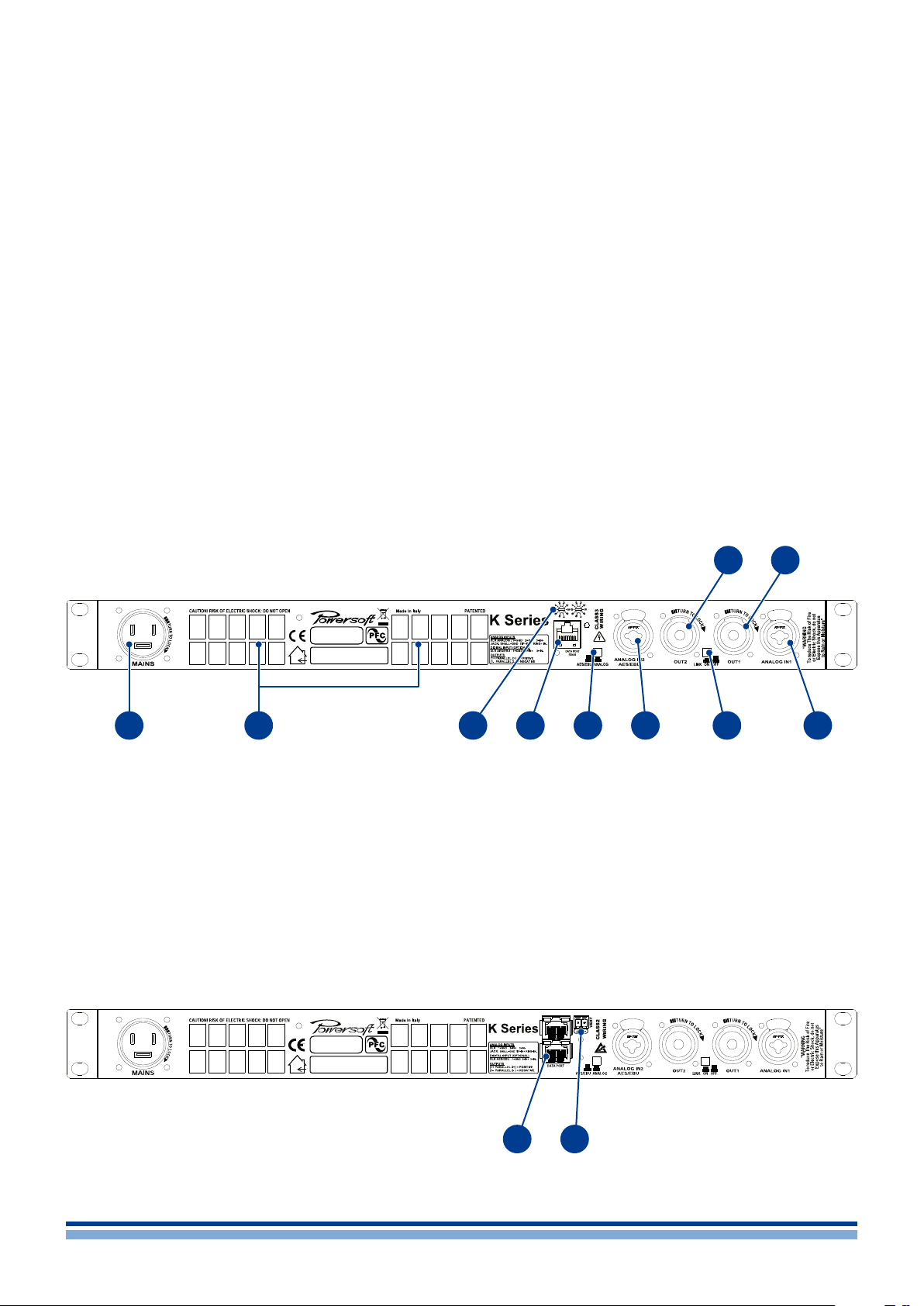
K6, K8, K10, K20 rear panel.
10
9
1 2 4
1. Mains plug
2. Air vents
3. Serial ID selector for the RS485 port
(non AESOP version only)
4. RS485 serial port (non AESOP version only)
5. AES3/analog switch for input 2
6. Input 2: channel 2 analog input in analog
mode or AES3 input in AES3 mode, according
to the position of the switch in #5
K6, K8, K10, K20 AESOP rear panel.
3
7. Link button: link input from channels 1 and 2
8. Input 1: channel 1 analog input
9. Speaker connector: output channel 1
10. Speaker connector: output channel 2
11. Ethernet+AESOP ports (AESOP version only)
12. Vext: 12 V
version only)
11
5 6
, 1A external voltage input (AESOP
DC
7 8
12
Front and rear panels | 5
Page 16
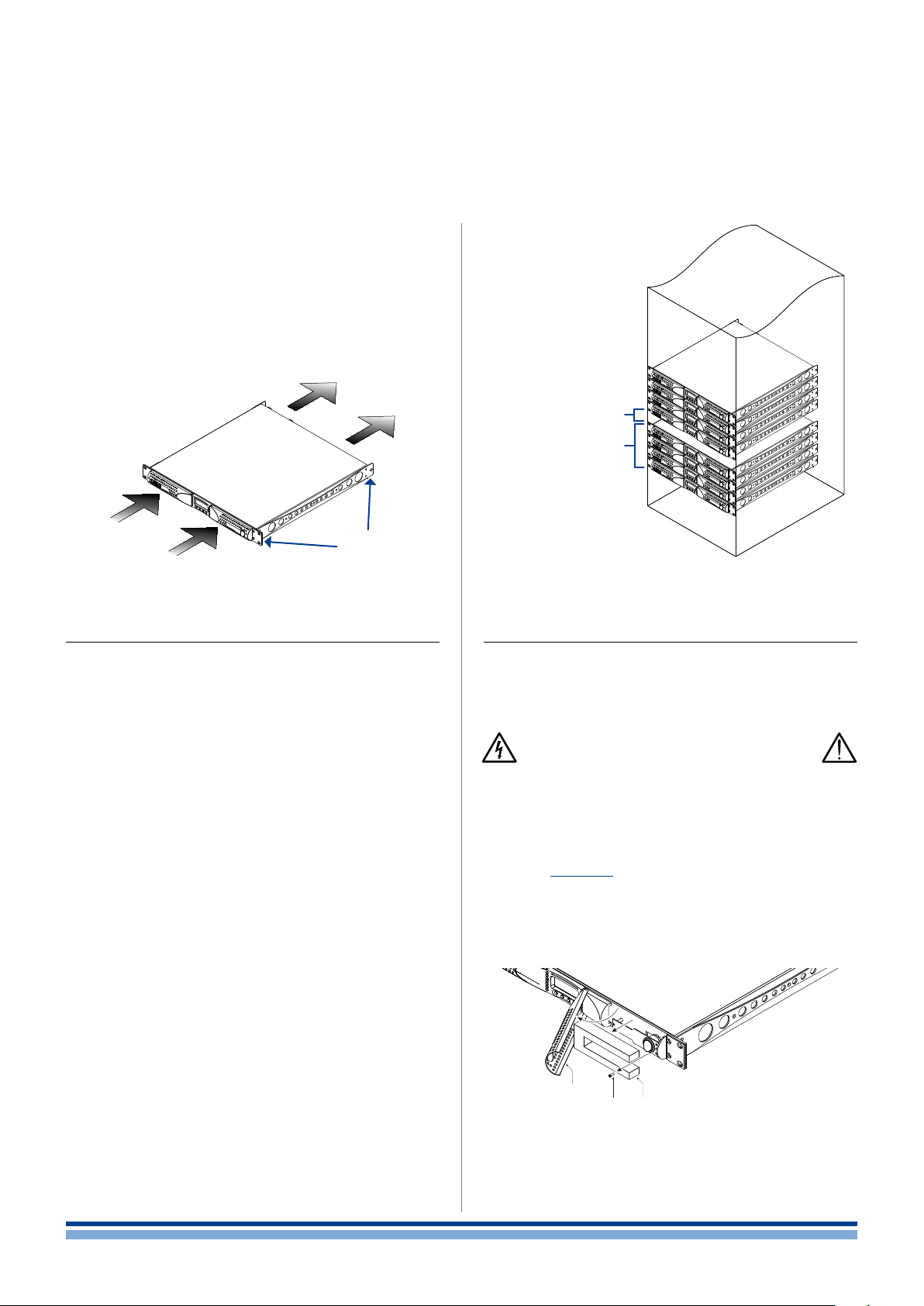
Installation
The common installation of the amplier is in rack cabinets: in order to limit the risk of mechanical damages, the
ampliers must be xed to the rack using both frontal and
rear mounting brackets.
Note: Instead of connecting the amplier to the power
grid directly, plug the amplier’s mains connections to a
power distribution panel inside the rack cabinet.
Mounting
Brackets
6
1 unit space every
4 amp stacked into
closed rack cabinet
4 amp stacked
FIGURE 4: Mounting brackets and air flow direction.
6 : 1.Cooling
Install the amplier in a well-ventilated location: the ventilation openings must not be impeded by any item such as
newspapers, tablecloths, curtains, etc; keep a distance of
at least 50 cm from the front and rear ventilation openings
of the amplier.
All Powersoft ampliers implement a forced-air cooling
system to maintain low and constant operating temperatures. Drawn by the internal fans, air enters from the front
panel and is forced over all components, exiting at the back
of the amplier.
The amplier’s cooling system features “intelligent” variable-speed DC fans which are controlled by the heatsink
temperature sensing circuits: the fans speed will increase
only when the temperature detected by the sensors rises
over carefully predetermined values. This ensures that fan
noise and internal dust accumulation are kept to a strict
minimum.
Should however the amplier be subject to an extreme
thermal load, the fan will force a very large volume of air
through the heat sink. In the extremely rare event that the
amplier should dangerously overheat, sensing circuits
shut down all channels until the amplier cools down to a
safe operating temperature. Normal operation is resumed
automatically without the need for user intervention.
X Series ampliers can be stacked one on top of the other
due to the efcient cooling system they are equipped with.
There is however a safety limit to be observed: in case
a rack with closed back panels is used, leave one rack unit
empty every four installed ampliers to guarantee adequate
air ow.
FIGURE 5: How to stack the amplifiers in closed racks.
6 : 2.Cleaning
Always use a dry cloth for cleaning the chassis and the
front panel. Air lter cleaning should be scheduled according
to the dust levels in the amplier’s operating environment.
Disconnect the AC main source before
attempting to clean any part of the amplifier
In order to clean the vent lters you need to remove the
front cover: never attempt to open any other part of the unit.
By means of a screwdriver Phillips PH1, unscrew the
screws that lock the left and right cover grils on the front
panel (ref. FIGURE 6), gently lift the covers and remove the
lters. You may use compressed air to remove the dust from
lters, or wash it with clean water: in the latter case ensure
that the lters are dry before reassembly.
cover grill
screw lter
FIGURE 6: Cleaning air filters.
6 | K Series | User guide
Page 17
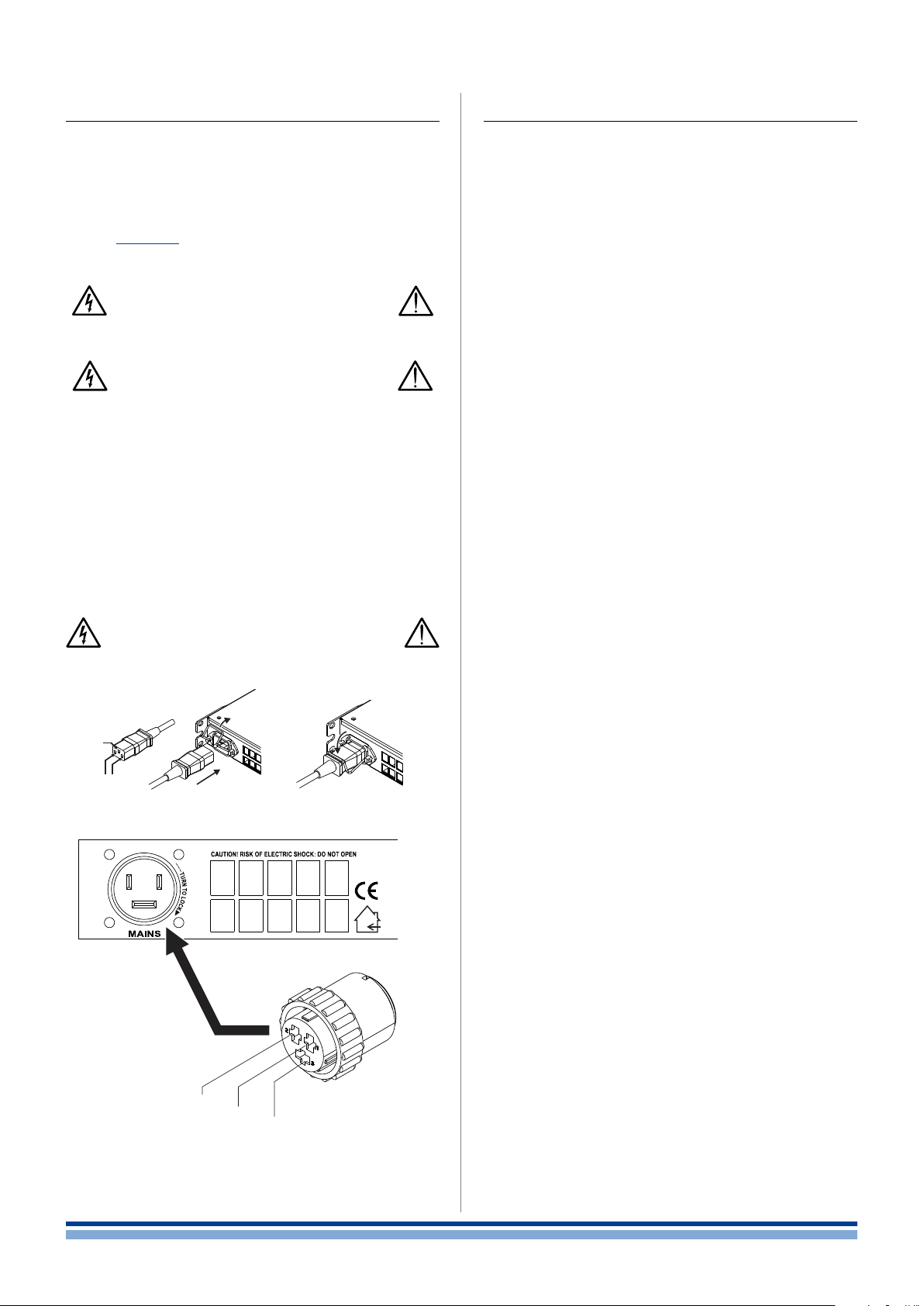
6 : 3.AC mains supply
6 : 4.Precautions regarding installation
The AC Main connection is made via the
AMP CPC 45A connector in K6, K8, K10 and K20;
IEC C20 connector in K3 and K2.
The FIGURE 7 shows how to connect the mains power
cable to the amplier.
Make sure the AC mains voltage used
is within the acceptable operating
voltage range: 115V-230V ±10%.
It is important to connect the ground
for safety, do not use adapters that
disable the ground connection.
All K Series ampliers have an automatic power factor
correction system – PFC – for a perfect mains network
interface. The PFC minimizes the reactive power reected
on the network and reduces the harmonic distortion on the
voltage/current waveform: in this way the amplier is seen
as a resistive load from the mains network. Furthermore, the
system allows performance to be maintained even in case
of varying mains voltage.
Connection to the mains shall be done
only by a electrotechnical Skilled person
according the national requirements of
the countries where the unit is sold
A
ground
open the lock
and insert the plug
lock the plug
Placing and using the amplier for long periods of time
on heat generating sources will affect its performance. Avoid
placing the amplier on heat generating sources. Install this
amplier as far as possible from tuners and TV sets. An
amplier installed in close proximity of such equipment may
experience noise or generic performance degradation.
The power cord type provided with the amplier are
LAPP OLFLEX191 3G6 / SJT 3XAWG10
for K6, K8, K10 and K20.
Bahoing SJT 3x16AWG or I-sheng SGIS 3G 1,5 mm
2
for K3 - K2.
WARNING: TO PREVENT FIRE OR ELECTRIC SHOCK
This device must be powered exclusively by earth con-
nected mains sockets in electrical networks compliant
to the IEC 364 or similar rules.
Install K6, K8, K10 and K20 into rack cabinet.
With K6, K8, K10 and K20 a sectioning breaker be-
tween the mains connections and the amplier must
be installed inside the rack cabinet. Suggested device
is 32A/250VAC, C or D curve, 10kA.
With K2 and K3 provide a sectioning breaker between
the mains connections and the amplier. Suggested
device is 16A/250VAC, C or D curve, 10kA.
Before powering this amplier, verify that the correct
voltage rating is being used.
Verify that your mains connection is capable of satisfy-
ing the power ratings of the device.
Do not use this amplier if the electrical power cord is
frayed or broken.
mains
B
32 1
N
Neutral
FIGURE 7: Mains connecors; A) IEC C20 in K2 and K3;
B) AMP CPC 45A in K6, K8, K10 and K20.
L
Line
GND
Protective
earth
Output terminals are hazardous: wiring connection to
these terminals require installation by an instructed
person and the use of ready made leads.
Take care to secure the output terminal before switch-
ing the device on.
To avoid electrical shock, do not touch any exposed
speaker wiring while the amplier is operating.
Do not spill water or other liquids into or on the amplier.
No naked ame sources such as lighted candles
should be placed on the amplier.
Do not remove the cover. Failing to do so will expose
you to potentially dangerous voltage.
It is absolutely necessary to verify this fundamental
requirement of safety and, in case of doubt, require an
accurate check by qualied personnel.
The manufacturer cannot be held responsible for
damages caused to persons, things or data due to an
improper or missing ground connection.
Contact the authorized service center for ordinary and
extraordinary maintenance.
Installation | 7
Page 18

Connections
Make sure the power switch is off before attempting to
make any input or output connections.
By using good quality input and speaker cables, the likelihood of erratic signal behavior is reduced to a minimum.
Whether you make them or buy them, look for good quality
wires, connectors and soldering techniques.
7 : 1.Signal grounding
There is no ground switch or terminal on the K Series
ampliers. All shield terminals of input connections are directly connected to the chassis. This means that the unit’s
signal grounding system is automatic. In order to limit hum
and/or interference entering the signal path, use balanced
input connections.
In the interests of safety, the unit MUST always operate
with electrical safety earth connected to the chassis via
the dedicated wire in the 3-wire cable (ref. Chapter 6 : 3.AC
mains supply). Never disconnect the ground pin on the AC
mains power cord.
Analog input
XLR-M pinout
Pin 1 GND
Pin 2
Pin 3
Analog input
TRS Jack pinout
Tip
Ring
Sleeve GND
HOT
COLD
HOT
COLD
A
B
GND
GND
7
HOT
2
3
1
COLD
S
R
HOT
T
COLD
7 : 2.Analog input
Analog input is provided by means of two Neutrik XLR
connectors in K2 and K3 or a couple of XLR/jack hybrid
combo connectors in K6, K8, K10 and K20 ampliers. Signal
polarity for XLR and TRS plugs is shown in FIGURE 8.
FIGURE 9: Analog input in K2, K3 (top)
and K6, K8, K10, K20 (bottom).
7 : 3.Analog line output
Line out is provided in K2 and K3 via a couple of XLR
connectors on the rear panel. In DSP equiped models, the
output signal is pre-DSP, being a replica of the input signal.
Analog line output
XLR-F pinout
Pin 1 GND
Pin 2
Pin 3
FIGURE 8: Signal polarity in balanced connections;
HOT
COLD
A) XLR-M plug; B) TRS jack; C) XLR-F plug.
C
HOT
2
3
1
GND
COLD
7 : 4.Digital Input
On DSP equiped models, the XLR input for channel 2
can switch to an AES3 digital input. The AES3/analog pushbutton located nearby the channel 2 XLR input connector
toggles the XLR between analog and digital input.
FIGURE 10: Analog line output in K2, K3.
8 | K Series | User guide
FIGURE 11: Digital input in K2, K3 (top)
and K6, K8, K10, K20 (bottom).
Page 19

In AES3 mode
CH1
CH2
Single-ended load
Single-ended load
speakON
connector
Channel 2
output
stage B
CHB +
CHB +
CHB –
CHB –
B
speakON
connector
Channel1
output
stage A
CHA +
CHA +
CHA –
CHA –
A
1+
2+
1–
2–
1+
2+
1–
2–
1+
2+
1–
2–
1+
2+
1–
2–
the channel 2 analog line out is off;
the channel 1 analog input can be used as redundant
input if the digital input fails.
The AES3 connection carries a channel pair through a
110 Ω nominal impedance wire in the form of a balanced
(differential) digital signal: in AES3 XLR connectors the identication of hot and cold pins is not an issue; take care to
never tie pin 2 or pin 3 (balanced signals) to pin 1 (ground).
Avoid the use of microphone cables in AES connections:
impedance mismatch can result in signal reections and
jitter, causing bit errors at the receiver.
7 : 5.AESOP
The AESOP standard can transport a single bidirectional Fast Ethernet (IEEE 802.3u, 100 Mbit/s) control data
stream and two independent separate AES3 digital audio
monodirectional streams using one Cat5 cable.
All K Series amplier with the optional KAESOP board
installed are equipped with at least two RJ45 connectors,
each of them being a single AESOP port, capable of sending and/or receiving data and audio.
If the amplier has only two RJ45 plugs, these will be
on the front panel. If four plugs are present, the rear two
will be “primary” ports, while the two on the front panel are
“secondary” ports.
Primary ports allow both data and AES3 streams;
secondary ports, on the other hand, are data-only ports,
allowing Ethernet connections only.
Cat5 standard twisted pair cables shall be used for connections up to 100 meters (328 ft). RJ45 pinout must comply
to TIA/EIA-568-B and adopt the T568B scheme pinout, as
show in TABL E 1.
For more details about networking and AESOP please
refer to Section: Network operations (p. 24).
TABLE 1: EtherCON/RJ45 T568B scheme pinout.
RJ45 connector
seen from
the front end
Color code (TIA/EIA-568-B) Pin
1 2 3 4 5 6 7 8
ORANGE / WHITE 1
ORANGE 2
GREEN / WHITE 3
BLUE 4
BLUE / WHITE 5
GREEN 6
BROWN / WHITE 7
BROWN 8
7 : 6.Loudspeaker connections
K6, K8, K10, K20 K2, K3
CLAS S 3 WI RING CLASS2 WIRING
Output terminals are hazardous: wiring connection
to these terminals require installation by an
instructed person and the use of ready made leads.
Take care to secure the output terminal
before switching the device on.
Two Neutrik NL4MD speakON connectors are located
on the rear panel, each of them being a single output to
loudspeaker.
Pins 1+ and 2+ are physically bridged to the positive pole;
pins 1– and 2– are physically bridged to the negative pole.
In order to remain within safe operating conditions,
when using low impedance loads – i.e. 4 � or less (8 � or
less in bridge mode) –, connections must be made with a
four wire cable. Use suitable wire gauges to minimize power
and damping factor losses in speaker cables.
7 : 6.1. Bridge-tied load
Bridge-tied load connection can be achieved as described in FIGURE 12. In analog mode, only the input of
channel 1 needs to be wired: link channel 2 to channel 1
by means of the link pushbutton located on the rear panel.
When operating with digital inputs – i.e. AES3 and
AESOP – link the channels via software: do not switch the link
pushbutton.
1+
CHA +
1–
CHA –
2+
CHA +
2–
CHA –
1+
CHB +
1–
CHB –
2+
CHB +
2–
CHB –
1+
CHA +
1–
CHA –
2+
CHA +
2–
CHA –
1+
CHB +
1–
CHB –
2+
CHB +
2–
CHB –
Single-ended load
1+
2–
1–
2+
speakON
connector
Channel1
Single-ended load
1+
2–
1–
2+
speakON
connector
Channel 2
Bridge-tied load
1+
2–
1–
2+
speakON
connector
Channel 1
1+
2–
1–
2+
speakON
connector
Channel 2
CH1
CH2
output
stage A
A
output
stage B
B
output
stage A
A
LINK
output
stage B
B
FIGURE 12: Loudspeaker connections: singleended loads (top), bridged-tied load (bottom).
Connections | 9
Page 20

7 : 6.2. Internal signal path polarity
In order to increase the power’s supply energy storage
efciency, signals coming from each channel pairs are polarity reversed, one with respect to the other within the pair,
when entering the amplier. This ensures a symmetrical use
of the voltage rails: if, for example, both channels’ 1 and 2
input signals are going through a peak at the same time,
channel 1’s energy will come from the positive voltage rails
while channel 2, whose polarity is reversed with respect to
channel 1, will be fed energy from the negative voltage rails.
In this manner, the power supply will work symmetrically,
with one channel catered by the positive rails and the other
by the symmetrical negative rails. Channel 2’s signal will be
polarity reversed once more at the output connectors to
ensure that both channels output with the same polarity as
their corresponding input signals.
7 : 8.RS-485 connection
K Series ampliers without an optional KAESOP board
can be remotely controlled via an RS-485 connection.
Remote connection data cables must have an 8P8C
modular plug – namely RJ45 plug – to be inserted in the
rear port labelled “DATA PORT”.
By plugging an RJ45 plug and selecting the unit’s remote
ID via the rotary trimmers, the amp is ready to be remotely
controlled. Please note that ID numer 00 is not allowed.
Channel 1
input
Channel 2
input
rst polarity
inversion
Amp
second polarity
inversion
Channel 1
output
Channel 2
output
FIGURE 13: Internal signal path polar-
ity with example input signals. Both channels
1 and 2 are fed the same sine signal.
7 : 7.V Ext
The V Ext terminal is used to remotely manage the DSP
in K Series DSP amplier and enable remote on/off.
K Series provided with a KAESOP board have a dedicated 2 pin Phoenix connector MCV 1,5/ 2-G-3,81 - 1803426
located near the rear Ethernet ports. K Series with the RS485 serial port implement the V Ext connection on pin 2 (pin
7) of the RJ45 rear connector (ref. FIGURE 15).
When the V Ext port is powered by and external 12 V
(1 A max) power supply, the internal controller allows to control the DSP – if present – even without AC mains supply,
and allows serial communication – via RS-485 or ethernet
communication in KAESOP equiped models – for remote
on/off via the Armonía Pro Audio Suite software.
DC
FIGURE 17: Data port and ID selectors for serial con-
nection; note that ID numer 00 is not allowed.
The recommended arrangement of the connections is a
series of point-to-point (multidropped) nodes – i.e. a line or
bus. Ideally, the two ends of the line should be terminated
with a resistor, typically 120 � for twisted pairs. Powersoft
recommend the use of Ethernet Cat5 straight through –
patch – cables with pin/pair assignments TIA/EIA-568-B,
i.e. T568B (ref. TAB LE 1).
1
2 3 4 5 6 7 8
–
+
V
ext
GND
FIGURE 15: Front view of the RJ45 connector
with T568 B wiring: RS-485 pinout.
FIGURE 14: V Ext phoenix connector MCV 1,5/ 2-G-3,81.
10 | K Series | User guide
FIGURE 16: RJ45 (8P8C) plug.
Page 21

LEDs and display menu
8
In all K Series ampliers, the combination of the front
panel buttons together with the LCD display allow the user
access to detailed information and complete control over
the amplier’s status. Each button has multiple functions
and the display shows the current active function for each
button. This chapter illustrates all the functions and settings
accessible via the amplier front panel.
All the setup and settings functions described in this
section can be also accessed through a computer with
Powersoft’s Armonía Pro Audio Suite software. Armonía is
a software environment that offers an easy to use end user
remote control interface and signal processing capabilities.
Armonía Pro Audio Suite is available for free on the
Armonía forum:
http://www.powersoft-audio.com/en/armonia-forum
Please note that when an Armonía client is connected to the
amplier, any local operation is overridden by the software.
8 : 1.LED chart
The LED columns on the front of the amp can work as
output voltage or current meters. When the LED bars are set
to meter output voltage, for example, the meters on the LCD
screen will indicate output current values. The vice versa is
true: LED bars set as output current meters, LCD display
bars become output voltage meters.
8 : 2.Front display
When the amp is turned on, the main screen appears
after a short presentation.
The rst line of the screen will read “WAIT” while the system undergoes an initial batch of internal tests to determine
the status of the amp. If all parameters are normal, “READY”
will replace “WAIT” on the display.
System parameters are continuously monitored by the
internal controller. If any parameter value should fall out of
its correctly operating range, a code error relative to that
particular parameter will appear on the third line of the LCD
meter at the corresponding channel number. Should the
parameter be out of range for both adjacent channels, the
error code will appear in between the two compromised
channels.
CH1 READY READY CH2
V I VI
lock
mute mute menu
Color Solid Blinking
Signal clipping
RED
YELLOW
GREEN output level2 -3 dB
GREEN output level2 -6 dB
GREEN output level2 -9 dB
GREEN output level2 -15 d B
input signal is above
GREEN
1
In case of a short circuit protection event, the LCD screen will read “PROT”.
2
With respect to the output clipping threshold.
OR
channel muted
for protection
Temperature
above 85°C
output level2 -2 dB
-60 dBV
output level2 -18 d B
TABLE 2: LED chart.
1
OR
OR
Ton e
detection
problem
Critical
temperature
(80° - 85°C)
FIGURE 18: K Series front display.
The fourth line of the front panel LCD screen shows the
functions of the buttons immediately below. A beep conrms that a button has been pressed; please note that this
sound is not mutable.
Pressing the button directly below the “menu” label on
the LCD screen gives access to the amplier’s main menu.
If an Armonía client is connected to the amplier, a yellow
shadow will appear in the software workspace view, signaling local access to the amplier.
8 : 2.1. How to navigate the main menu
The K Series main menu can be accessed by pressing the rst button on the right, underneath the LCD label
“m enu”.
The up and down arrows allow to scroll the menu items.
To access further menu voices branching off a specic
menu item, select it and press the “menu” button once.
Some submenus in the K Series amps require the user
to set a numerical value for specic parameters using the
front panel buttons. In order to speed this process up, these
submenus dedicate two of the four available buttons to
switching to a fast or slow parameter increment mode.
LEDs and display menu | 11
Page 22

When in the “slow” mode, the up and down arrows in-
Max Mains Current
22 A rms
Source selection
Source mode
Gain trim
If no link
Display Amp data
Edit Amplier name
Analog Out
Analog DSP Out
AES3 Out
1
AES3 DSP Out
KAESOP Out
2
KAESOP DSP Out
Output attenuation
Input gain/sens
Inuput select
Max output voltage
Max mains current
Clip limiter CH1
Clip limiter CH2
Gate CH1
Gate CH2
Mute at Power on
Idle Mode
see “DSP Settings” diagram
Device mode
Addressing mode
Set address
Show net cong
Audio
Repeat (default)
Forward to AES3-A
Forward to AES3-B
Forward to both
IP address
subnet mask
Default gateway
1
Available only with optional KDSP board
2
Available only with optional KAESOP board
crease or decrease the parameter by a the smallest amount
possible. The “fast” mode will increase or decrease the
parameter value by an amount equal to 10 times the amount
increased in the “slow” mode.
8 : 2.2. Menu diagrams
On the following pages you will nd two diagrams providing an overview of the structure of the Main menu (FIGURE
20) and DSP settings menu (FIGURE 21) accessible via the
front panel on K Series ampliers.
Max Mains Current
22 A rms
back
back
FIGURE 19: Fast/slow data emission.
For example: in “slow” mode a single “+” button press
will increase the Max mains current from 22 A to 23 A; in
“fast” mode a single “+” button press will increase the Max
mains current from 22 A to 32 A.
- +
Toggle fast/slow input
- +
fast
slow
Menu
Settings
Display
Local presets
Setup
Amplier Settings
DSP Settings
Network Settings
Output meters
Temperature
Mains meters
Amplier name
Lock presets
Locked bank size
Recall local preset
Save local preset
Change lock code
Erase all presets
Hardware Info
Hardware Monitor
LCD contrast
Set Keylock code
Service
1
2
12 | K Series | User guide
FIGURE 20: Main menu diagram.
Page 23

Output attenuation
Input gain/sens
Inuput select
Max output voltage
Max mains current
Clip limiter CH1
Clip limiter CH2
Gate CH1
Gate CH2
Mute at Power on
Idle Mode
see “DSP Settings” diagram
Device mode
Addressing mode
Set address
Show net cong
Audio
Analog Out
Analog DSP Out
AES3 Out
AES3 DSP Out
KAESOP Out
1
2
KAESOP DSP Out
Repeat (default)
Forward to AES3-A
Forward to AES3-B
Forward to both
IP address
subnet mask
Default gateway
1
1
1, 2
AES3-XLR rear panel
AES3-A
AES3-B
Display Amp data
Edit Amplier name
Source selection
Source mode
Gain trim
If no link
1
Available only with optional KDSP board
2
Available only with optional KAESOP board
Parallel from L
Parallel from R
Stereo
Mute
Analog
LEDs and display menu | 13
Page 24

Common Settings
CH1 Settings
CH2 Settings
CH1 Setup
CH2 Setup
Input EQ
Reset Input Section
Reset Output Section
Source Selection
AES3
Cross limit
Sound speed (m/s)
EQs
LP lter
HP lter
Polarity
Ch delay (us)
Gain (dB)
Peak limiter
Power limiter
Damping Control
Stereo
Parallel from CH1
Parallel from CH2
Mono Mix
Gain trim (dB)
If no link:
PEQ#
Active
Freq. (Hz)
Slope (dB/oct)
Shape
Active
Freq. (Hz)
Slope (dB/oct)
Shape
In phase
Reversed
Active
Thresh. (Vpk)
Attack (ms)
Release (ms)
Analog
Mute
Active
Freq. (Hz)
Gain (dB)
Q factor
Type
Butterworth
Bessel
Link.-Riley
FIR Lin Phase
Hybrid FIR
Butterworth
Bessel
Link.-Riley
FIR Lin Phase
Hybrid FIR
Peaking
Low Shelving
High Shelving
Low pass EQ
High pass EQ
Bandstop
Bandpass
Allpass
identical to CH1 Settings
Aux Dly (ms)
Diagnostics
Mode
Soft knee
Thresh. (W)
Attack (ms)
Release (ms)
Mode
Equiv. Rout (Ω)
Tone in alarm
Tone in freq
Tone in Vmin
Tone in Vmax
Tone out gen
Tone out ampl
Tone out freq
Tone out alarm
Tone out Vmin
Tone out Vmax
Load alarm
Load Zmin
Load Zmax
Measures
OFF
TruePower
Power vs V @ 8Ω
Power vs I @ 8Ω
14 | K Series | User guide
identical to CH1 Setup
FIGURE 21: DSP settings diagram.
Page 25

Settings
9
9 : 1.Amplifier settings: Output attenuation
The output attenuation screen sets the amplier’s output attenuation level.
The user can choose whether to set output attenuation
for channel 1, channel 2 or both by cycling through the right
most button. The “+” and “-” buttons change the value of
the output attenuation in the range from 0 to -30 dB. A
single “+” or “-” button press will increase or decrease the
output attenuation by 1 dB.
Note: for ideal sonic performance, select a 0 dB output
attenuation (meaning no attenuation), and select the proper
gain/sensitivity level as explained in the next paragraph.
Output attenuation
-13 -13dB
back C1+2
FIGURE 22: Output attenuation.
-
+
9 : 2.Amplifier settings: Input Gain/Sensitivity
All K Series ampliers allow selection of input sensitivity
to allow correct sensitivity matching with other third party
equipment.
The user can choose whether to set the input gain/sensitivity for channel 1, channel 2 or both by cycling through
the right most button. The “+” and “-” buttons change the
value of the input gain and corresponding sensitivity. The
allowed gain values are 26 dB, 29 dB, 32 dB and 35 dB.
TABLE 3 shows the input sensitivity values for the K
Series ampliers. These are the maximum RMS voltage
values of a 1 kHz sine wave input before clipping occurs at
the output stage. These values are reported with respect to
the amplier’s gain.
Gain K2 K3 K6 K8 K10 K20
26 dB 4.48 V 5.30 V 5.11 V 5.50 V 6.34 V 7. 37 V
29 dB 3.17 V 3.75 V 3.62 V 3.90 V 4.49 V 5.22 V
32 dB 2.47 V 2.66 V 2.56 V 2.75 V 3.18 V 3.68 V
35 dB 1.59 V 1.8 8 V 1.81 V 1.95 V 2.25 V 2.62 V
TABLE 3: Input sensitivity (in RMS volt) @ 1 kHz vs gain.
Gain dBV dBu V
26 dB 25.0 27 18
29 dB 21.6 24 12
32 dB 19.0 21 9
35 dB 15.6 18 6
TABLE 4: Maximum balanced input signal vs gain.
rms
9 : 3.Amplifier settings: Input select
K Series ampliers allow the user to choose three different input modes (if available): Analog, AES3
KAESOP2.
Each of these inputs can either be processed by the
internal DSP (if installed) or not. The up and down buttons
on the “Input select” screen toggle between the available
input sources. The “sel” button locks the selected option.
The available signal routing path congurations are:
Analog Out
Analog input and direct output
Analog DSP Out
Analog input routed to the internal DSP
AES3 Out
AES3 input, direct output
AES3 DSP Out
AES3 input routed to the internal DSP
KAESOP Out
KAESOP input, direct output
KAESOP DSP Out
KAESOP input routed to the internal DSP
2
1
1
1 2
1
and/or
9 : 4.Amplifier settings: Max output voltage
The max output peak voltage of K Series ampliers can
be set by the user.
It is possible to set output peak voltage levels for channel 1, channel 2 or both by pressing the “C1+2” button. The
“+” and “-” buttons change the value of the max output peak
voltage. Available voltage ranges for each model are shown
in TABLE 5.
K2 K3 K6 K8 K10 K20
40/140 V 40/165 V 40/15 3 V 40/169 V 40/200 V 40/225 V
TABLE 5: Maximum output voltage (V
peak
).
The maximum balanced input signal before saturation
of the input stage of the amplier occurs with respect to the
amplier’s gain is presented in TA BLE 4.
1
Available only with optional KDSP board
2
Available only with optional KAESOP board
Settings | 15
Page 26

9 : 5.Amplifier settings: Max mains current
9 : 7.Amplifier settings: Gate CH1/CH2
The maximum current the amplier can draw from the
mains can be set by the user through the front panel of all K
Series ampliers.
The “+” and “-” buttons allow setting of the value of the
max rms mains current. Acceptable values are within the
8A to 16 A for K2 and K3 and from 15 A to 32 A range for all
other K ampliers.
Max mains current
23 A rms
back
FIGURE 23: Max mains current.
Setting the maximum mains current determines the current threshold at which a C-Type current breaker will trip.
- +
fast
9 : 6.Amplifier settings: Clip limiter CH1/CH2
This function allows to mute the amplier channels
individually if the input signal amplitude falls below the
threshold shown in
Gating the output is delayed by 5 seconds after the input
signal falls below the threshold. If the channel is muted, the
bottom green LED in the corresponding front panel LED
column is off.
Gain dBV dBu
26 dB -54 -52
29 dB -57 -55
32 dB -60 -58
35 dB -63 -61
TABLE 6: Gate threshold vs gain.
9 : 8.Amplifier settings: Mute at power on
This functions allows the user to automatically mute all
channels when the amplier is turned on. Toggle the on or off
status by pressing the front panel button below the “sel” label.
If this function is enabled, a “Muted” label will appear at
the main screen next to each channel at the next power on.
Press the button underneath the “mute” label in the front
screen to unmute the channel.
The clip function can be used to prevent distortion
caused by clipping of the output signal.
Please note that clip limiters can be set independently
for both channels.
CAUTION: disabling clip limiters can
potentially damage loudspeakers.
Max mains current
Clip Limiter CH1:ON
Clip Limiter CH1:ON
back
FIGURE 24: Clip limiters.
The amplier’s internal clip limiters should not be deactivated unless the limiting function is implemented by an external device such as digital system controllers. In this case,
it is extremely important to correctly set limiting parameters
in order to preserve loudspeakers from excessively powerful and potentially hazardous driving signals.
sel
Idle state timeout
22 min
ok -
FIGURE 25: Idel state timeout.
slow
+
9 : 9.Amplifier settings: Idle mode
The idle mode function is a power saving feature. When
this function is activated, the output stage is turned off after
no input signal greater than a selected threshold is detected
for a user selectable amount of time, saving about 40 W of
power per channel. This results in reduced heating, longer
amplier and fans life, and, especially for xed installations
which are permanently turned on, a lower electricity bill.
Exiting from idle mode is quasi-instantaneous.
In order to set the time after which the amplier enters
in idle mode, push the rightmost button labelled “sel” when
the idle mode line is highlighted. This will open the “Idle
state timeout” screen. Using the central buttons, select the
desired time. In the “slow” mode, a single button press will
increase or decrease the time by one minute. The “fast”
mode will bring this up to 10 minute steps. The timeout
range goes from 0 to 720 minutes.
16 | K Series | User guide
Page 27

9 : 10.DSP Settings: Common settings
Analog back up cabling
carrying the same signal as the CH1 of the AES3 feed
Digital main cabling
IN1
(analog)
IN2
(AES/EBU)
CH1 out
CH2 out
DSP Source Selection mode: Parallel from CH1
main digital connection
analog backup connection
(used if digital fails)
CH1
CH2
The KDSP is an advanced digital sound processor board
based on a oating point SHARC® DSP.
KDSP can be used to optimize the performance of the
audio system by means of fully customizable crossovers
and equalizers. Exceptionally high reliability is guaranteed
in all conditions by advanced limiters, and continuously
monitored loudspeaker parameters. This chapter illustrates
the features and operational modes of the KDSP board.
9 : 10.1. Source selection
This menu allows to choose the input signal to be processed by the DSP. The possible options are:
Stereo: the signal coming from channel 1 is processed
and routed out to output channel 1. Similarly, the input
signal coming from Channel 2 is processed and then
routed out to output channel 2.
correctly matched between analog input and AES3
input (use the AES3 Gain trim parameter), the switch
between AES3 and analog will be inaudible.
When using the analog input to backup a failed AES3
feed, the analog input connection must be setup based on
source type of input AES3 stream:
AES3 from rear XLR – the primary audio signal for
this conguration is an AES3 fed via the rear XLR
(AES3DSPOut ref. Chapter 7 : 4.Digital Input).
The backup analog cable, with an analog signal identical to that provided by AES3, should be plugged in
the channel1 XLR input. If the AES3 feed should fail,
the amplier will automatically fall back to channel 1
analog input (we suggest to set the DSP source selection to “Parallel from CH1”). The signal levels of both
primary AES3 and backup analog signals should be
carefully matched. This can be done using the gain
trim parameter or by adjusting the analog signal level.
Parallel from CH1: the input signal from channel 1
feeds two parallel, distinct and independent processing branches. The result of one branch is sent to
output channel 1, while the result of the other branch is
sent to output channel 2.
Parallel from CH2: the input signal from channel 2
feeds two parallel, distinct and independent processing branches. The result of one branch is sent to
output channel 1, while the result of the other branch is
sent to output channel 2.
Mono Mix: the input signals from channel 1 and 2 are
summed together and routetd to both output channels
in order to maintain a consistent output level.
9 : 10.2. AES3
This menu controls the AES3 input stream options. The
AES3 source can enter the amplier from the rear XLR connector or from the KAESOP board (if present) based on the
type of input selection (ref. Chapter 9 : 3.Amplier settings:
Input select).
9 : 10.2.1. Gain trim (dB)
This menu allows the user to set the gain to be applied
to the signal coming from the AES3 digital input. Setting a
0dB gain makes the full-scale digital signal equivalent to a
20 dBu analog input signal.
9 : 10.2.2. If no link
This menu controls the amplier’s behavior should the
AES3 signal connection fail or become unreliable. The AES3
connection is considered unreliable when transmission
errors are greater than 1% of total data transmitted. The
possible options are:
Mute: when the AES3 connection fails, the amplier
mutes the output.
IN1
Analog back up cabling
carrying the same signal as the CH1 of the AES3 feed
Digital main cabling
(analog)
CH1
CH2
IN2
(AES/EBU)
DSP Source Selection mode: Parallel from CH1
main digital connection
analog backup connection
(used if digital fails)
FIGURE 26: AES3 from XLR.
AES3 from KASEOP – the primary audio signal for
this conguration is an AES3 fed via the RJ45 port
(KAESOPDSPOut ref. Chapter 7 : 4.D igita l Input).
The backup analog cable, with an analog signal
identical to that provided by the KAESOP, should be
plugged in the channel 1 XLR and channe 2 XLR (set
to analog) connectors. The DSP’s source selection
can be set to any possible input. If the KAESOP feed
should fail, the amplier will automatically fall back to
the analog input on the channels 1 and 2. The signal
levels of both primary KAESOP and backup analog
signals should be carefully matched. This can be
done using the gain trim parameter or by adjusting the
analog signal level.
IN1
Analog back up cabling
carrying the same signal as the CH1 of the AES3 feed
Main digital AES3 stream via RJ-45
Analog back up cabling
carrying the same signal as the CH2 of the AES3 feed
(analog)
CH1
CH2
IN2
(analog)
DSP Source Selection mode: Parallel from CH1
main digital connection
analog backup connection
(used if digital fails)
FIGURE 27: AES3 from KAESOP.
CH1 out
CH2 out
CH1 out
CH2 out
Analog: when the AES3 connection fails, the amplier
will rely on the analog input as backup. This source
signal switching is done in real time in order to avoid
any glitches in the audio feed. If the input levels are
When the AES3 stream is lost and the analog backup
kicks in, a message on the front panel is displayed and if a
remote client (e.g. Armonía) is connected to the amplier, an
alarm is sent to it.
Settings | 17
Page 28

9 : 10.3. Cross limit
In case of power limiting of only one channel (ref.
Chapter 9 : 6.Amplier settings: Clip limiter CH1/CH2), the
gain reduction on one channel is mirrored to the other
channel in order to maintain consistent signal levels. This
is useful in two ways speakers where the limitation of one
channel alone leads to an unbalanced sound. This function
can be turned on or off.
9 : 10.4. Sound speed (m/s)
This menu allow the user to set the sound velocity used
for time to distance conversions throughout the local interface. It can be set from 320 m/s to 360 m/s.
1
2 3
PEQ #12 Peak
Freq=21205Hz G=+12dB
BW=0.63oct Q=21.3
back
5 74
6
CH1
edit
9 : 11.DSP Settings: Channel settings
All of the following settings are available for both channel
1 and channel 2. In all the following menus and submenus,
the channel number whose properties are being edited is
shown in the top right hand corner of the menu. If a specic
parameter affects both channels, the top right hand corner
will report this as “1+2”.
To/from
other channel
AES3
GAIN
INPUT
SELECT
Analog
SigGen SigGen
PROCESSING
Raised cosine lters EQ
INPUT EQGAIN
INPUT
MAIN
DELAY
FIGURE 28: EQ settings: 1) Filter number; 2) Filter type;
3) Channel; 4) Frequency; 5) Bandwidth; 6) Gain; 7) Q.
9 : 11.1. EQs
This menu gives access to the parametric output equalizer interface. This menu lists the 16 parametric lters one
by one. The current selected lter number is shown on the
CHANNEL
PROCESSING
To output stage
16 bands parametric EQ Custom FIR Enhanced limiter
GAIN
CHANNEL
PEQ16
18 | K Series | User guide
FIR EQ
CHANNEL
DELAY
output
monitor
Lo-PASS
FILTER
Output current
Output voltage
Hi-PASS
FILTER
POLARITY
Load impedance
FIGURE 29: DSP processing diagram.
PEAK
LIMITER
Load power
estimation
estimation
TruePOWER
LIMITER
Cable loss
compensationIIR and FIR linear phase crossover
DAMPING
CONTROL
Page 29

left of the rst line. By pressing the up and down pointing
arrows, it is possible to move from one lter to the next. The
lter parameters are reported on the screen.
Active: determines if the lter is enabled or not (at
response
Gain(dB): lter gain. Can be set only if the lter is a
peaking or shelving lter. Acceptable values go from
-15 to +15 dB in 0.1 dB steps.
Q factor: quality factor of the lter. This can be set
for all lters except shelving lters. Acceptable values
range from 0.1 to 30 with 0.1 steps.
Bandwidth (oct): the bandwidth of the lter expressed
in octaves around the central frequency. This value is
determined by setting the Q factor.
Ty p e: allows the user to select the lter type:
1. Peaking
2. Low Shelving (3 to 15dB/oct)
3. High Shelving (3 to 15dB/oct)
4. Low pass EQ
5. High pass EQ
6. Bandstop
7. Bandpass
8. Allpass
Peaking
Lo-Shelv
Hi-Shelv
Lo-pass
Hi-pass
Band-stop
Band-pass
All-pass
Frequency
20Hz-20kHz
Gain
±15 dB
Slope
3-15dB/octQ0.1- 3 0
TABLE 7: Filters parameters.
By pressing the “edit” button, the settings for the selected
lter can be modied. TABL E 7 summarizes which parameters can be edited according to the selected lter type.
9 : 11.2. Lo-pass/Hi-pass filters
This menu allows the user to congure the crossover lters. There are 2 available crossover lters: a lowpass and a
highpass. By combining both, the result will be a bandpass
response.
Both traditional Innite Impulse Response as well as
brickwall linear phase Finite Impulse Response lters are
implemented. If a FIR lter in the EQ section is enabled, a
FIR crossover lter cannot be enabled at the same time. The
low pass and high pass lters can be edited (active status,
frequency, slope, lter type) by the user via the main LCD
screen.
The classic IIR crossover lter shapes that can be selected as a high pass or low pass lter are: Butterworth,
Bessel, and Linkwitz-Riley. In the rst 2 cases, the frequency
parameter in the edit window denes the -3 dB point, in the
latter, the -6 dB point. The slope is freely selectable from
a minimum of 6 dB/octave (1st order lter) to 48 dB/octave
(8thorder lter).
The FIR lters can be selected as normal (FIR Linear
Phase) or enhanced (Hybrid FIR). The enhanced version of
the lters gives a higher rejection of out of band signals, at
the expense of a small phase modication (30°@400Hz). In
both cases, the minimum working frequency is relative to
the desired latency. Standard setting limit this to 400 Hz.
For this reason it is advisable to use FIR lters to crossover
upper midranges or mid-high drivers for which the phase
coherency is a key point.
9 : 11.3. Polarity
This menu allows to reverse the signal polarity. The two
selectable modes are:
In phase: the signal’s polarity is not altered
Reversed: the signal’s polarity is reversed.
9 : 11.4. Channel Delay
This menu allows to set a single channel output delay.
This is helpful to time-align two different loudspeakers
on the two output stages. The selectable delay varies from
0 to 32 ms (about 11 meters at 344 m/s sound speed), with
a single sample step (equal to 1/96000th second or 10.4 us,
about 3.5 mm)
9 : 11.5. Gain
This menu changes the channel gain, from -40 dB to
+15dB, with a 0.1 dB step.
9 : 11.6. Limiters
The limiting process in sound reinforcement is a way to
protect loudspeakers from accidental damage; therefore,
limiters are a safeguard against excessive signal peaks
and/or signal power. They not only protect from sudden
signal peaks but also they protect against to an over power
delivering.
Bear in mind that limiting does not only prevent occasional
damage, but it rst and foremost guarantees a long component life. The two main purposes of limiting process are:
Limit over-excursion: an impulsive signal can reach the
speakers and cause damage due to over-excursion of
the voice coil that is driven out of the magnetic gap.This
can damage the diaphragm (breaking or deforming it).
Limit over-heating: delivering high power to the voice
coil may lead to overheating. This can damage the isolation or burn out the voice coil. Another evident high
power driving effect is power compression, noticeable
in low frequency speakers.
In order to prevent the mentioned phenomena two kinds
of limiters are provided:
Peak limiter: protects against mechanical damages.
The peak limiter may also be used to control amplier
clipping. Designers should set this limiter’s parameters
as a function of both the maximum displacement
(Xmax) of the diaphragm as well as the speaker’s
maximum tolerated voltage.
Settings | 19
Page 30

Power limiter: protects speakers against thermal
damage when excessive power is applied for extended
periods of time, resulting in overheating and, eventually, burning. Designers should be aware of the maximum long term power safely applicable to speakers
(AES power rating). An interesting approach to RMS
limiting is one that uses coil temperature control. A
complete knowledge of the driver’s limits allows to
keep the temperature level in a safe interval not only to
avoid damage but to maintain the speaker in a “linear”
zone that avoids power compression.
9 : 11.6.1. Peak Limiter
The peak limiter avoids potentially dangerous displacements of the cone (an excursion larger that allowed). It acts
by reducing the amplier gain in order to reduce the measured output peak voltage. To limit the dangers of dangerous
very fast transient signals, all limiters implement a look
ahead time of 0.5 ms.
As a rule of thumb, use the declared peak power or
twice the program power as a loudspeaker safe-zone output power.
The peak limiter’s setting do not change with the number of parallel speakers connected to the amplier, this is
because the same voltage is applied to all the components
in a parallel circuit. When deciding parameters for a peak
limiter of an amplier with many loudspeakers connected to
it in parallel, the peak power to be taken into consideration
is that reaching only a single speaker.
You can refer to the following formulas:
2
V
P
V
peak
Where Re is the nominal impedance of only one driver, P
is the peak power and V
A peak limiter, used with a very short attack time (i.e.,
with a very rapid onset), can also be useful in limiting the
maximum peak voltage in distributed constant voltage lines.
Powersoft designed the K Series limiters as protective
measures; therefore, they are not meant to “color” the
sounds such as dynamic compressors can do. With this in
mind, time constants for these limiters should be selected
so as to limit potentially harmful phenomena which persist
for no more than one or two periods of the related signal
bandwidth.
TABLE 8 gives a few examples of attack and release
times with respect to the frequency range of the signal to
be limited.
peak
peak
=
peak
Re
= √ Re ∙ P
is the peak output voltage.
peak
peak
Active:ON
CH1
Thresh.(Vpk):169
Attack(ms):10
back sel
FIGURE 30: Peak limiter settings.
The peak limiter menu allows the user to dene the fol-
lowing parameters:
Active: toggles the power limiter’s on/off status;
Threshold (V
the gain begins to be reduced;
Attack: the attack time, i.e. the response time of the
limiter intervention;
Release: the decay time, i.e. the time constant after
which the limiter’s action is released and the gain restored to the nominal value.
In order to avoid choking the exceptional dynamic range
offered by K Series ampliers, the peak limiter is designed
to ignore signal peaks lasting less than the attack time parameter. Moreover, the limiter has an additional lookahead
buffer (0.5 ms) to soften clipping and minimize distortion,
effectively yielding superior sonic performance.
When tweaking the peak limiter’s levels, it is preferable
to rst setup the time parameters, and then adjust the
threshold voltage. When editing the threshold value, the
display shows the gain reduction (GR) in dB enforced by
the limiter.
This information, together with the limiting voltage referred to the signal in the input amplier stage (I) expressed
in dBu, is displayed in real time to allow monitoring of the
limiting actions as they are performed.
Thresh.(Vpk)
): the peak voltage threshold at which
pk
CH1
169 Vpk
GR= 0.0dB I= 11.7dBu
ok
- +
fast
Octave
band (Hz)
63 45 720 x16
125 16 256 x16
250 8 128 x8
500 4 32 x8
1000 2 8 x4
> 1000 1 2 x2
TABLE 8: Attack and release times per octave bands.
20 | K Series | User guide
Attack time
(ms)
Release time
(ms)
Atk/Rel ratio
FIGURE 31: Peak limiter: threshold
voltage and gain reduction.
Page 31

9 : 11.6.2. Power lmiter
Given the low efciency of electromechanical transducers, almost 50% of power reaching the voice coil is transformed into heat.
The power limiter is intended to avoid melting the voice
coils of drivers while at the same time exploiting their maximum performance, therefore the power limiter should not
be engaged at normal working levels. The power limiter
acts by decreasing the amplier’s gain in order to reduce
the power delivered to the load.
A correct power limiting is not an easy task and is multifaceted, based on a number of variable, like the knowledge
of the component heat dissipation and the goals that must
be achieved. Therefore may be difcult and a little bit empirical decide thresholds and constants time. Power limiters
behavior base their operations on a mix based on threshold,
dynamic behavior of the output readings (voltage and current) and the type of output readings monitored.
Check the gain reduction: in order to obtain the optimal
sound it should not be greater than 2-4 dB even for the
loudest piece of music. Please note that a common musical signal has very high peaks, but a rather small average
level (high crest factor). A stationary tone has a much higher
average power (e.g. a stationary sine wave has 3 dB crest
factor) even if it “sounds” less loud to the human ear.
There are three main operating modes for the K Series
power limiters.
TruePower™: the amplier’s active output power is es-
timated by measuring the load current. The TruePower
limiter is a Powersoft patent technology useful to avoid
overheating of the voice coil; it can however also be
used to avoid power compression. The DSP provides
the measurement of the real power delivered (and then
dissipated) to the coil, ignoring the apparent power
handled by the line.
Empirical observation yields the following equation
P
P
where P
is the declared AES power and P
AES
mum power the speaker can dissipate “in real life”.
If the P
power, known as P
is not available, the average or continuous
AES
can be used as well; however, it is
rms
important to proceed with caution in evaluating how the P
value is obtained. If no other values are declared, this rule of
the thumb can be used: the P
below the peak power (¼ of the peak power).
It is very important to note that, contrary to what happens with the peak limiter, setting the TruePower limiter
parameters must take into account the number of speakers
connected to the amplier. This is due to the fact that the
real power is calculated not only with the output voltage
(which is identical for all speakers connected in parallel) but
also with the output current (which changes according to
the number of parallel speakers).
Determining the ideal time parameters for TruePower
limiters is a very empirical process. As a guide, consider
this simple rule: larger the coil, larger the thermal inertia,
larger the time constant (ref. TABLE 9).
AES
=
max
3
can be estimated as 6 dB
AES
is the maxi-
max
rms
Voice coil size
(inches)
1” tweeter 10-20 100 300
1.5” tweeter 20-30 150 300
2” comp. driver 20-40 200 400
3” comp. driver 30-50 300 500
4” com. driver 40-60 500 3000
2” midange 30 -10 0 500 3000
3” midbass 50-150 1000 5000
4” woofer 100-200 2000 5000
4” woofer 150-250 4000 8000
6” woofer 250-500 6000 10000
Threshold
(W)
Attack time
(ms)
TABLE 9: Filters parameters.
Power vs voltage @ 8 ohm: the amplier’s output
power is estimated by measuring the RMS value of the
output voltage, assuming an 8 ohm load.
This mode allows to create settings that work well for
any number of speakers connected in parallel. For
example, if a “power @ 8 ohm” limiter is set to limit
the output power to 150 W, a single cabinet will be
delivered a maximum of 150 W with 8 ohm load. Two
speaker cabinets connected in parallel will be delivered a maximum of 300 W with 4 ohm load (8 ohm
loads in parallel) and so on.
This limiter is a pure RMS limiter whose functioning is based
solely on the voltage module measured at the amplier output. Differently from the TruePower limiter, this limiter does
not take into account the real part of the power; however, it
has the advantage of being independent from the number of
cabinets linked together, just as a peak limiter.
Some attention is needed to set the power threshold.
The P
ing is declared, the P
can be used if it is available. If no other power rat-
AES
can be used as well; however, the
rms
RMS parameter is a value related to the maximum manageable power and not the real power. Proceed with caution
because the manageable power could be greater than the
real power. Some constructors declare the RMS power at
the minimum impedance point of the speaker; this, again,
may lead to an overestimation of the true power values the
speaker can handle. If no other values are available, the
following rule of the thumb can be used: the P
estimated as 6 dB below the peak power (¼ of the peak
power).
In order to preserve the driver in the long term, once the
maximum power limit is decided upon, consider a power
reduction of up to 3 dB of that value.
In order to use this limiter correctly, it is important to recalculate the equivalent power at 8 ohm. For example, with
an 4 ohm speaker with 500 W maximum RMS power, the
equivalent power at 8 ohm needs to be calculated as follow:
1. calculate the RMS voltage value needed to generate
the maximum RMS power on the 4 ohm speaker:
V
= √ Re ∙ P
where V
rms
is the RMS voltage of the speaker, P
rms
rms
its average or continuous power and Re the nominal
impedance. In the above example the RMS voltage of
the 4 ohm speaker is V
= 44.7 V.
rms
Release
time (ms)
can be
rms
is
rms
Settings | 21
Page 32

2. calculate the power delivered to a speaker with nominal impedance of 8 ohm with that V
2
V
eqiv
rms
=
8
where P
is the equivalent power on the 8 ohm
equiv
speaker and V
P
is the RMS voltage value calculated at
rms
voltage:
rms
step 1. In this example (4 ohm speaker) this is 250W.
This is the threshold power to set in the limiter.
The time constants for the Power vs voltage @ 8 Ohm
limiter can be set in the same way as for the TruePower
limiter.
Power vs current @ 8 ohm: similar to the case
power vs voltage @ 8 ohm, but based on the current
measured at the output.
9 : 11.7. Damping Control
This unique and patented feature allows to add a “virtual” series resistor to the amplier output. This is done to
obtain the desired damping factor with any cabling used.
For this end, the virtual series resistor can also have a negative value to compensate cabling resistance.
For example, using a 10 meter cable to powering the
subwoofer means adding a series parasitic resistance of
about 0.3 Ohms. By enabling the damping control, a virtual
negative series resistance can be added to compensate the
cable resistance.
When damping control is enabled, a lowpass filter
cutting around 400 Hz is automatically inserted
into the amplifier chain. This feature is intended
to be used only for subwoofer applications.
In this case the formula to derive the average or continu-
ous power, known as P
where I
is the RMS current.
rms
from the RMS current is:
rms
2
P
= I
∙ Re
rms
rms
This limiter is particularly useful in situations where the
parameter to be controlled is the output current (e.g. for
tweeters).
It is also useful for special applications such as large
coil speakers with current controls. When determining this
limiter’s parameters, it is necessary to take into account the
number of speakers connected in parallel to the amplier.
The power limiter menu allows to set the following
parameters:
Mode: allows to determine the power limiter
OFF/ON: toggle le limiter on or off;
TruePower: sets the limiter mode to TruePower
Power vs V @ 8 �: sets the limiter mode to Power vs
voltage @ 8 ohm
Power vs I @ 8 �: sets the limiter mode to Power vs
current @ 8 ohm
Soft knee: toggle ON/OFF
Thresh.(W): threshold output power level expressed in
watt at which the gain begins to be reduced;
Attack (ms): the time it takes for the limiter to start
reducing the amplier gain once the output power has
exceeded the threshold value;
Release (ms): the time constant after which the gain
is restored to its nominal value once the output power
has returned below the threshold.
When editing the power threshold value, the display
shows the gain reduction (GR) in dB enforced by the combined effect of the peak and power limiters. This information, together with the average power truly delivered to the
load (P
), is displayed in real time to allow monitoring of the
avg
limiting actions as they are performed.
Another advantage offered by the damping control
feature is that in adding the series equivalent output resistance to the amplier chain, the variation of the voice coil
resistance due to heating can be taken into account. This
allows to obtain a correctly damped bass response at average working condition, where the voice coils is subject to
heating due to the passage of current.
For example, if the subwoofers are going to work at
close to full power, an additional negative resistance of 1 to
2 Ohms should be added to compensate the high resistance
generated by the heated voice coils to obtain a correctly
damped response. On the other hand, if the same subwoofers are working at low power, a smaller negative resistance
should be added: in this case the cooler voice coil presents
a smaller series resistance to be compensated.
Leaving too high an equivalent series resistance results
in an overdamped system.
Section area
(mm2 - AWG)
2 x 1.5 - 16 AWG R = 12 �/km
2 x 2.5 - 13 AWG R = 7.4 �/km
2 x 4 - 11 AWG R = 4.5 �/km
Nominal
resistance
Length
(ms)
5 0 ,12
10 0,24
20 0,48
5 0,07
10 0,15
20 0,30
5 0,05
10 0,09
20 0 ,18
Resistance
(ohm)
TABLE 10: Typical speaker cabling resistance.
On TA B L E 11 notice the exceptionally high value (3.8
ohm) when the driver reaches it thermal limit.
Average power/
rated power
10% 1.4 dB 1.0 �
20% 2.0 dB 1.4 �
50% 2.8 dB 2.1 �
100% 4.5 dB 3.8 �
Power
compression
Equivalent series
resistance
to a 8 � driver
TABLE 11: Typical resistance increase
due to voice coil heating.
22 | K Series | User guide
Page 33

9 : 12.DSP Settings: Channel setup
9 : 12.1. Auxiliary delay
This delay is a further input delay: it acts before the input
EQ and is independent from the input EQ stage.
9 : 12.2. Diagnostics
The diagnostics tool allows the user to program and test
the integrity of the input and/or output line.
The input test is based on the detection of a pure tone
(generated by an external tone generator) on any input
line.
The output test reliess on the measurement of the
impedance at a well dened frequency: the amplier
can generate a pure tone and measure the voltage and
current at the generated tone frequency. It is therefore
possible to recalculate the impedance at that specic
frequency.
9 : 12.2.4. Load Alarm
The output Load Monitor allows to detect the impedance
load at a certain frequency. The high resolution algorithm
implemented in this tool allows accurate measures.
Load alarm: enable/disable the impedance detection.
Load Zmin: the minimun allowed impedance threshold
value (range 0 Ω - 500 Ω, step of 0.1 Ω ).
Load Zmax: the maximum allowed impedance threshold value (range 0 Ω - 500 Ω, step of 0.1 Ω ).
9 : 12.2.5. Measures
Pressing the button measures gives access to a sub
menu where the various amplier readings are available.
Tone i n: measurements of the input tone at the selected frequency.
Tone out: measurements of the output tone at the selected frequency.
Z load: measurements of the load at the selected frequency.
When an alarm condition is met, the user can be informed
of the event via software or directly from the amplier.
9 : 12.2.1. Tone in alarm
The tone in alarm can measure the integrity of any input line feeding signal into the amplier. This detector can
measure a tone applied by an external generator.
Tone in alarm: enable/disable the input tone detection
Tone in freq: the frequency of the tone that has to be
detected (range 20 Hz - 24 kHz, step of 10 Hz).
Tone in Vmin: the minimun thershold value that has
been detected (range 0 V
rms
- 4 V
rms
, step of 10 mV
rms
).
Tone in Vmax: the maximum threshold value that has
been detected (range 0 V
rms
- 4 V
rms
, step of 10 mV
rms
).
9 : 12.2.2. Tone out gen
The inner tone generator allows the user to generate a
tone that can be used to check the integrity of the output
line. This tone should be used outside of the freqeuncy
bandwidth of the driven speaker to avoid can be listen.
Tone out gen: enable/disable the internal generator.
Tone out ampl: the output voltage of th generator
(range 0 V
Tone out freq: the frequency of the tone that has to be
generated and eventually detected (range 20 Hz - 24
kHz, step of 10 Hz).
- 20 V
rms
, step of 1 V
rms
rms
).
9 : 13.DSP Settings: Input EQ
This menu allows to turn on / turn off the input processing block. This can be useful when resetting the amplier to
the original “output processing only” behavior without using
any software.
Turning off the Input EQ, all input processing set up using, for example, the Armonía Audio Suite can be bypassed
at once.
It is advisable to save amplier presets with this setting
turned off: in this way when loading presets the user can be
sure that only the output processing is enabled. The burden
of re-enabling and setting up input processing is left to the
remote control software.
9 : 14.DSP Settings: Reset input section
This operation disables the input processing (input EQ,
input gain and delay) and resets the aux delay to zero.
9 : 15.DSP Settings: Reset output section
This function disables all output EQ, limiters and damping functions.
9 : 12.2.3. Tone out alarm
The output tone detection can measure the presence of
a tone generated by an external or internal generator.
Tone out alarm: enable/disable the output tone detection.
Tone out Vmin: the minimun detected threshold voltage value (range 0 V
Tone out Vmax: the maximum detected threshold voltage value (range 0 V
- 20 V
rms
- 20 V
rms
, step of 1 V
rms
, step of 1 V
rms
rms
rms
).
).
Warning: this operation may potentially
damage connected speakers.
Pay special attention to shutting down any audio source
before using this function.
Settings | 23
Page 34

Network operations
10
Network capabilities and network setting menus are
available only for K Series ampliers equipped with a
KAESOP board.
KAESOP stands for K (as in Powersoft’s K Series) AES3
and Ethernet Simple Open Protocol. Powersoft’s KAESOP
is designed to provide high reliability to live applications in
harsh environments where Quality of Service must be guaranteed. Electromagnetic and radio frequency interference
(EMI and RFI) originating from a high power audio and light
system must not degrade audio quality or cause a control
link interruption. Moreover, a single cable or device failure
should not affect the overall system performance.
10 : 1.Introduction to AESOP
The AESOP standard can transport a single bidirectional
Ethernet 100 Mbps control data stream and two separate
AES3 digital audio monodirectional streams using one Cat5
cable.
All K Series amplier with the optional KAESOP board
installed are equipped with at least two RJ45 connectors,
each of them being a single AESOP port, capable of sending and/or receiving data and audio.
If the amplier has only two RJ45 plugs, these will be
on the front panel. If four plugs are present, the rear two
will be “primary” ports, while the two on the front panel are
“secondary” ports.
Primary ports allow both data and AES3 streams;
secondary ports, on the other hand, are data-only ports,
allowing Ethernet connections only.
Cat5 standard twisted pair cables shall be used for connections up to 100 meters (328 ft). RJ45 pinout must comply
to TIA/EIA-568-B and adopt the T568B scheme pinout, as
show in TABL E 1 p. 22.
Please note that even if crossed Ethernet cables
would work control wise, crossed cables are not
to be used for KAESOP connections: they will
not allow the AES3 streams to flow correctly.
10 : 1.1. Data stream
The data stream in the AESOP is implemented by a 100
Mbit Ethernet connectivity with auto-sense.
Each device can use a static IP address assigned by
the user. Alternatively, it can be set to automatically congure itself without user intervention following the Zeroconf
protocol.
The dual port design in K Series ampliers allows for
daisy chain and redundant ring topologies. A fault-bypass
built-in feature takes into account the possibility of loosing
an intermediate device or having a faulty cable link without
compromising the ring integrity.
The KAESOP board detects bad quality connections by
counting errors on the Ethernet control. Faulty connections
are automatically switched from 100 Mbit/s to 10 Mbit/s
to attempt to keep the link active even in the worst case
scenarios.
10 : 1.2 . Audio
Audio is distributed to devices via the AESOP protocol
by 2 independent and separate AES3 streams labeled
AES3-A stream, AES3-B stream. These are carried by two
Cat5 wire pairs unused in the 100 Mbit Ethernet protocol.
AES3 is a license free and well known standard guaranteeing low-latency, high reliability and excellent audio
quality. A single AES3 stream can carry a stereo audio
signal. The AESOP protocol can therefore handle four audio
channels.
When a K Series amplier is powered off or if it is unavailable, a passive high frequency relay circuit allows the
audio signal to pass through, preserving the network chain
connection integrity.
When the device is powered up, the internal circuits
automatically select the most appropriate AES3 stream direction and bypass the relay, re-buffering actively the AES3
signal. The direction is maintained until errors are detected
on the AES3 receiver circuit. When errors or link failure are
detected, the direction is swapped, to build-up a new path
for the audio. In a fraction of a second (no more than 50ms),
some of the devices in a ring will swap to the other direction,
restoring the audio streaming.
10 : 1.3. Ethernet internal switch
All control data streams in the KAESOP system are
transported via an Ethernet protocol. Inside all K Series
ampliers is an Ethernet switch connected to each RJ45.
This means that the bidirectional data stream can enter/
exit one port and exit/enter any other port, either alongside
AES3 streams or on its own.
Internal routing of Ethernet networking is automatic and
not user controllable. An internal switch provides packet
ooding block services in order to allow building networks
with a ring topology.
10 : 1.4. Forwarding and repeater modes
Each K Series amplier can be congured to handle the
pair of AES3 streams embedded in the AESOP protocol in
one of two basic network modes: repeater and forwarder.
These are true connection “building blocks”; it is therefore important to understand these two modes thoroughly
before attempting to create or modify larger and more complex amplier networks.
The following are denitions of the terms used in this
section:
24 | K Series | User guide
Page 35

AES3-A stream: AESOP digital audio stream A (two
channels)
10 : 2.KAESOP repeater mode
AES3-B stream: AESOP digital audio stream B (two
channels)
AES3-XLR stream: AES3 digital audio stream via the
rear panel XLR connector.
PORT 1, PORT 2: primary RJ45 AESOP ports
PORT 3, PORT 4: secondary RJ45 Ethernet ports
Port 1
(primary)
Port 2
(primary)
AES3
XLR
TheIn the Repeater mode, any AES3 stream received on
PORT 1 will be repeated on PORT 2 and vice-versa: if the
AES3 stream is received on PORT 2 it will be repeated on
PORT 1.
The Repeater mode is the default device mode setting.
This applies to both AES3-A stream and AES-B stream
independently. If an AES3 stream (A or B) is present as input
at both RJ45 ports (this can happen when a ring network
topology is used), the internal AESOP repeater feeds only
one of the two identical streams keeping the second stream
in standby.
If for some reason the rst stream fails the second
stream is used as a backup audio source.
Port 1
(primary)
Port 2
(primary)
XLR
AES3
AES3-A stream
AES3-B stream
Control data stream
Port 3
(secondary)
Ethernet switch
Port 4
(secondary)
FIGURE 32: Repeat AES3-A from PORT 1 to PORT 2.
For consistency, primary ports are placed in the rear of the
amp, while secondary ports are at the front. Notice that AES3
streams are monodirectional, while data stream is bidirectional.
Port 1
(primary)
Ethernet switch
Port 2
(primary)
XLR
AES3
AES3-A stream
AES3-B stream
Control data stream
AES3-A stream
AES3-B stream
Control data stream
Port 3
(secondary)
Ethernet switch
Port 4
(secondary)
FIGURE 34: Repeat AES3-B from PORT 1 to PORT 2.
Port 1
(primary)
Ethernet switch
Port 2
(primary)
AES3-A stream
AES3-B stream
Control data stream
XLR
AES3
Port 3
(secondary)
Port 4
(secondary)
FIGURE 33: Repeat AES3-A from PORT 2 to PORT 1.
Port 3
(secondary)
Port 4
(secondary)
FIGURE 35: Repeat AES3-B from PORT 2 to PORT 1.
Network operations | 25
Page 36

10 : 3.KEASOP forward mode
When the amplier is set in forward mode, the AES3 signal coming into the amplier from the AES3-XLR connector
is forwarded to both of the primary RJ45 ports.
The rear panel toggle button near to the channel 2 XLR
connector must be in the “AES/EBU” position. There are
three ways the AES can be forwarded: forward to AES3-A,
forward to AES3-B, forward to both.
10 : 3.1. Forward to AES3-A
The amplier’s AES3-XLR connector will be routed to the
AES3-A stream on both primary PORT 1 and 2 (FIGURE 36).
If there is an AES3-B stream incoming from either primary RJ45 ports (1 or 2), this will be repeated on the other
primary port (FIGURE 39).
10 : 3.2. Forward to AES3-B
The amplier behaves just as in the forward to AES3-A
mode but with respect to the AES3-B stream.
The AES3-XLR stream will be routed to the AES3-B
stream on both primary PORTS 1 and 2 (FIGURE 37).
The AES3-A stream, if present will be repeated from/to
primary RJ45 ports 1 and 2.
10 : 3.3. Forward to both
The amplier’s AES3-XLR stream will be routed to both
AES3-A and AES3-B streams on both primary PORTS 1
and2 (FIGURE 38).
Repeater functionality will be disabled.
IMPORTANT: In any forward mode, the amplifier
can accept as the sole AES3 input signal the
one coming from the AES3-XLR connector.
The RJ45 ports cannot, input AES3 signals to the amplifier.
Port 1
(primary)
Port 3
(secondary)
Ethernet switch
Port 2
(primary)
Port 4
(secondary)
XLR
AES3
AES3-A stream
AES3-B stream
Control data stream
FIGURE 36: Forward AES3-XLR to AES3-A.
For consistency, primary ports are placed in the rear of the
amp, while secondary ports are at the front. Notice that AES3
streams are monodirectional, while data stream is bidirectional.
Port 1
(primary)
Port 2
(primary)
AES3
XLR
Port 1
(primary)
Port 3
(secondary)
Port 1
(primary)
Port 2
(primary)
Ethernet switch
Port 4
(secondary)
AES3-A stream
AES3-B stream
Control data stream
FIGURE 38: Forward AES3-XLR to both.
Repeat is disabled.
Port 2
(primary)
XLR
AES3
XLR
AES3
Ethernet switch
Port 3
(secondary)
Port 4
(secondary)
FIGURE 37: Forward AES3-XLR to AES3-B.
26 | K Series | User guide
AES3-A stream
AES3-B stream
Control data stream
Port 3
(secondary)
Ethernet switch
Port 4
(secondary)
AES3-A stream
AES3-B stream
Control data stream
FIGURE 39: Forward AES3-XLR to AES3-B.
Repeat AES3-A from PORT 1 to PORT 2.
Page 37

10 : 4.Network robustness
K Series ampliers equipped with a KAESOP are capable of being networked routing both data and audio streams
to each other.
In dealing with networks of ampliers, one of the most
important aspects to consider, especially when working in
a critical application such as large venue sound distribution,
is the robustness of the network itself. Data and audio connections can be made fault proof by means of some level
of redundancy.
The degree of redundancy expresses how many network connections can break before sound is interrupted in
any one amplier part of the system.
A zero degree redundant system is not robust: the rst
connection to jump (either from a cable failure or even from
an amplier problem) means the whole system goes down.
A one degree redundancy system, on the other hand,
will continue working automatically if one (but no more than
one) connection fails.
K Series ampliers support up to two degrees redundancy thanks to the adoption of proper networking topology: by detecting any connection failure on both analog and
digital input K Series ampliers are capable to automatically
(and almost instantaneously) modify the audio feed direction to allow the output signal to remain uninterrupted.
The following section illustrates and analyzes some
common amplier network topologies with different degree
of redundancy.
Port 1
(primary)
Port 3
(secondary)
Port 1
(primary)
Port 3
(secondary)
Port 1
(primary)
Port 3
(secondary)
Port 1
(primary)
Port 3
(secondary)
Audio
Data
Audio + Data
Audio + Data
Audio + Data
Port 2
(primary)
Forward to AES3-A
Port 4
(secondary)
Port 2
(primary)
Repeat AES3-A
from PORT 2 to PORT 1
Port 4
(secondary)
Port 2
(primary)
Repeat AES3-A
from PORT 2 to PORT 1
Port 4
(secondary)
Port 2
(primary)
Repeat AES3-A
from PORT 2 to PORT 1
Port 4
(secondary)
FIGURE 40: Daisy chain - four port models.
AES3
source
XLR
AES3
AESOP
AES3-A stream
1
XLR
AES3
Control data stream
Network
data input
2
XLR
AES3
3
XLR
AES3
4
10 : 4.1. Daisy chain
Daisy chain is a wiring scheme in which multiple devices
are networked together in sequence, i.e. in series.
FIGURE 40 and FIGURE 41 show the diagrams of daisy
chain connections of 4 ampliers with four and two AESOP
ports respectivelly.
In both conguration, only the rst amplier – feeded
with the digital signal via the AES3-XLR – is set in forward
mode: any other amplier in the chain is a repeater.
Ethernet data are fed through any free port, either primary or secondary, and conveyed to the AESOP with the
AES3.
This daisy chain topology is not robust (zero degree of
redundancy). If any single AES3 or Ethernet cable connection is interrupted, the whole system fails.
10 : 4.2. Daisy chain with redundant AES3
A slightly more robust network with respect to the audio
system is the one illustrated in FIGURE 42 and FIGURE 43.
Two ampliers, the rst and the last one in the chain, are
set to work in forward mode. The remaining ampliers are
set to work in repeater mode.
Even if both the leading and the trailing amplier forward
the AES3 strem through the AESOP, there is no risk of data
collision; furthermore, all ampliers ara capable to switch
in real time to the best signal source in case of connection
failures.
This conguration implies the use of an AES3 patch bay
in order to feed with the same digital signal the leading and
trailing ampliers.
Audio
Forward to AES3-A
Port 1
(primary )
Port 1
(primary)
Port 1
(primary)
Port 1
(primary)
Audio + Data
Audio + Data
Audio + Data
Port 2
(primary)
Repeat AES3-A
from PORT 2 to PORT 1
Port 2
(primary)
Repeat AES3-A
from PORT 2 to PORT 1
Port 2
(primary)
Repeat AES3-A
from PORT 2 to PORT 1
Port 2
(primary)
Data
FIGURE 41: Daisy chain - two port models.
AES3
source
XLR
AES3
AESOP
AES3-A stream
1
XLR
AES3
Control data stream
Network
data input
2
XLR
AES3
3
XLR
AES3
4
Network operations | 27
Page 38

Port 1
(primary)
Port 3
(secondary)
Port 1
(primary)
Port 3
(secondary)
Port 1
(primary)
Port 3
(secondary)
Port 1
(primary)
Port 3
(secondary)
Port 1
(primary)
Port 1
(primary)
Port 1
(primary)
Audio
Port 2
(primary)
Forward to AES3-A
XLR
AES3
1
Port 4
Data
Audio + Data
Audio + Data
Audio + Data
(secondary)
Port 2
(primary)
Repeat AES3-A
from PORT 2 to PORT 1
Port 4
(secondary)
Port 2
(primary)
Repeat AES3-A
from PORT 2 to PORT 1
Port 4
(secondary)
Port 2
(primary)
Repeat AES3-A
from PORT 2 to PORT 1
Port 4
(secondary)
XLR
AES3
2
XLR
AES3
3
XLR
AES3
4
FIGURE 42: Daisy chain with AES3
redundancy - four port models.
XLR
AES3
Audio
Audio + Data
Audio + Data
Audio + Data
Forward to AES3-A
Port 2
(primary)
Data
Repeat AES3-A
from PORT 2 to PORT 1
Port 2
(primary)
Repeat AES3-A
from PORT 2 to PORT 1
Port 2
(primary)
1
XLR
AES3
2
XLR
AES3
3
XLR
AES3
AES3
source
AESOP
AES3-A stream
Control data stream
Network
data input
AES3
source
AESOP
AES3-A stream
Control data stream
Network
data input
Thanks to the auto-sync features implemented in K
Series ampliers, no syncronization mismatch occur between the two AES3 streams.
Failure cases:
damaged AESOP connection between amp n and n+1:
Ethernet network connection would be interrupted
but not the audio stream. The audio continuity is preserved thanks to the real-time switch of the AESOP
stream toward the uncorrupted source coming from
the trailing amplier. The amplier n+1 and the following lose the data connectivity.
damaged AES3 input connection: no sound inter-
ruption would be heard because the failured input is
immediatly replaced by the AESOP stream. Ethernet
connectivity is not affected by this kind of failure.
The robustness of this network is guaranteed for AES3
signals only, and for a single cable failure at a time (one degree ofredundancy). If two or more connections should fail,
one or more ampliers (depending on where the interruption
occurs) would be muted.
10 : 4.3. Daisy chain with AES3 and Ethernet redundancy
Similarly to the previous schema, both AES3 and
Ethernet connection are fed to the leading and the trailing
ampliers in the daisi chain network.
The AESOP protocol can handle data conict and manage real-time witching to a safe signal and/or data source.
This conguration implies the use of an AES3 patch bay
and an ethernet switch.
Failure cases:
damaged AESOP connection between amp n and n+1:
the audio and ethernet continuity is preserved thanks
to the real-time switch of the AESOP stream toward
the uncorrupted source coming from the trailing amplie r.
damaged AES3 input connection: no sound inter-
ruption would be heard because the failured input is
immediatly replaced by the AESOP stream. Ethernet
connectivity is not affected by this kind of failure.
damaged Etehrnet input connection: no data corrup-
tion would occur because the failured input is immediatly replaced by the AESOP stream. The audio stream
is not affected by this kind of failure.
Even if this network conguration implements both data
and audio redundancy, its robustness is the same of that
of the previous topology: la connettività è garantita per un
singolo guasto del cavo alla volta (un grado di ridondanza),
sia nei dati o nella rete audio.
Repeat AES3-A
from PORT 2 to PORT 1
Port 1
(primary)
Port 2
(primary)
FIGURE 43: Daisy chain with AES3
redundancy - two port models.
28 | K Series | User guide
4
Page 39

Port 1
(primary)
Port 3
(secondary)
Port 1
(primary)
Port 3
(secondary)
Port 1
(primary)
Port 3
(secondary)
Port 1
(primary)
Port 3
(secondary)
Audio
Data
Audio + Data
Audio + Data
Audio + Data
Port 2
(primary)
Forward to AES3-A
Port 4
(secondary)
Port 2
(primary)
Repeat AES3-A
from PORT 2 to PORT 1
Port 4
(secondary)
Port 2
(primary)
Repeat AES3-A
from PORT 2 to PORT 1
Port 4
(secondary)
Port 2
(primary)
Repeat AES3-A
from PORT 2 to PORT 1
Port 4
(secondary)
Audio
AES3
source
XLR
AES3
AESOP
AES3-A stream
1
XLR
AES3
Control data stream
Network
data input
10 : 4.4. Two degree redundant daisy chain
If the ampliers in the daisy chain are fed with mono
signal and the channel of each unit are linked – so that to
use the same input signal (ref. Chapter 9 : 10.1. Source selec-
tion) –, a two degree redundant connection topology can be
achieved.
Taking advantage of the “if no link” features in the
Network settings menu (ref. Cha pter 10 : 5.Network setting s
menu), the K Series can switch to the analog input when the
KAESOP stream fails. Bearing this in mind, it is possible to
achieve high degree of redundancy exploiting both digital
2
and analog inputs.
Remember that when operating with digital inputs – i.e.
AES3 and AESOP – channel link must be achieved via soft-
XLR
AES3
3
Data
XLR
AES3
4
ware: do not switch the link pushbutton.
The network topology is described in FIGURE 46.
FIGURE 44: Daisy chain with AES3 and
Ethernet redundancy - four port models.
Audio
Forward to AES3-A
Port 1
(primary)
Port 1
(primary)
Port 1
(primary)
Audio + Data
Audio + Data
Audio + Data
Port 2
(primary)
Repeat AES3-A
from PORT 2 to PORT 1
Port 2
(primary)
Repeat AES3-A
from PORT 2 to PORT 1
Port 2
(primary)
Data
Analog
AES3
AESOP
AES3-A stream
Control data stream
AES3
source
XLR
AES3
AESOP
AES3-A stream
1
XLR
AES3
Control data stream
Network
data input
2
XLR
AES3
3
XLR
AES3
Port 1
(primary)
Port 3
(secondary)
Port 1
(primary)
Port 3
(secondary)
Port 1
(primary)
Port 3
(secondary)
Port 1
(primary)
Audio
Data
Audio + Data
Audio + Data
Audio + Data
Port 2
(primary)
Forward to AES3-A
Port 4
(secondary)
Port 2
(primary)
Repeat AES3-A
from PORT 2 to PORT 1
Port 4
(secondary)
Port 2
(primary)
Repeat AES3-A
from PORT 2 to PORT 1
Port 4
(secondary)
Port 2
(primary)
XLR
AES3
CH2
analog
CH 1
XLR
1
XLR
AES3
CH2
analog
CH 1
XLR
2
XLR
AES3
CH2
analog
CH 1
XLR
3
Audio
Audio
Data
XLR
AES3
CH2
analog
CH 1
XLR
Analog
source
ADC
AES3
source
Network
data input
Repeat AES3-A
from PORT 2 to PORT 1
Port 1
(primary)
Port 2
(primary)
Data
FIGURE 45: Daisy chain with AES3 and
Ethernet redundancy - two port models.
Repeat AES3-A
4
Port 3
(secondary)
from PORT 2 to PORT 1
Port 4
(secondary)
4
FIGURE 46: Two degree redundant daisy chain
via AES3, Ethernet and Analog input.
Network operations | 29
Page 40

10 : 5.Network settings menu
The Network settings menu become available when the
KAESOP board is installed (ref. FIGURE 20).
Many of the menus in this section require the user to
select one functioning mode from a set of possible alternatives. These alternatives are all presented in a list. A black
diamond shape next to a specic item in the list indicates
that that is the selected option.
Device mode: this parameter sets the amplier mode
with respect to the AES3 stream (ref. Chapter 10 : 2.
KAESOP repeater mode and Chapter 10 : 3.KEASOP
forward mode). Available options are:
Repeater (default); Forward to AES3-A;
Forward to AES3-B;
Forward to both.
Note: when an amplier is in forward mode (either to
AES3-A, AES3-B or both) the amplier can only accept the
AES signal coming from the AES3-XLR connector. AES3
streams incoming from any other RJ45 port are ignored.
Addressing Mode: this parameter controls the IP ad-
dressing assignment strategy:
Manual: requires the user to set a valid static ad-
dress and subnet mask (and, optionally, the default
gateway). The PC should be on the same subnet of
the amplier if no routers are present between the
PC and amplier.
Automatic: lets the amplier ask and obtain a net-
work conguration from a DHCP server. Starting
from power-on, the amplier tries to obtain a valid
IP address from a DHCP server. After a timeout of
30 seconds, if an IP address is not obtained, the
amplier takes an automatic private address in
the range 169.254.x.y, but continues to search for
a DHCP server. When the DHCP becomes avail-
able, the address is updated. If no DHCP server
is available, the amplier obtains an IP address by
Automatic IP (local link addressing or ZeroConf).
The amplier behavior complies with RFC 3927, guaranteeing the interoperability with any host PC supporting this
standard.
from the selected AES3 stream is forwarded to both
amplier channels), Parallel from R (the right channel
from the selected AES3 stream is forwarded to both
amplier channels), Stereo (the right channel from
the selected AES3 stream goes to channel 1 or the
amplier; the right channel from the AES3 stream
goes to the amplier’s left channel).
Gain trim: this parameter trims the digital level of
the AES3 stream. The gain trim scale goes from +5
dB to -40dB with 0.5 dB steps with respect to 0 dB
equivalent of +13.5dBu. A 0 dBFS level in the AES3
stream corresponds to an absolute analog level of
+18.5dBu when a +5 dB gain trim level is applied.
If no link: this parameter allows the user to choose
the behavior of the amplier when the digital audio
stream is missing and the “Input selection” is set as
KAESOP OUT (or KAESOP DSP OUT). The
two possible alternatives are: Mute and Analog. In
Analog mode the amplier automatically switches
to CH1/CH2 analog input if the digital stream is
missing, returning to the digital stream in case this
should become available again. This mode could be
used to implement an analog backup connection for
the digital stream (ref. Chapter 10 : 4.4. Two degree
redundant daisy chain).
Set address: this menu allows to manually set the am-
plier’s IP address, subnet mask and default gateway.
Show net config: this menu shows the current net-
working conguration, either set by the user via the
“Set address” menu or obtained automatically if the
automatic addressing mode is selected.
Audio
Source selection: this menu allows the user to
select the AES3 stream source to feed the output
power stage. The AES3 signal can come from ei-
ther: AES3-XLR, AES3-A or AES3-B.
Source mode: this menu allows to selects the
channel(s) contained the selected AES stream to be
forwarded to the output power stage of the amplier.
The possibilities are: Parallel from L (the left channel
30 | K Series | User guide
Page 41

Display
11
The Display menu allows the user to monitor the system
status and performance.
11 : 1.Display: Output meters
The output meters screen shows important output sig-
nal information for the amplier.
By pressing the right most front panel button, the screen
view is toggled between information relative to channel 1,
channel 2 or relative to the sum of channels 1 and 2.
70 Vrms
9 Arms
630 Watt
back
FIGURE 47: Display: Output meters.
Zload=8.0 C1+2
11 : 3.Display: Mains meters
This screen displays the updated mains RMS voltage
and RMS current levels. Values are displayed in numbers
and as progress bars.
The current and voltage levels displayed in this screen
are approximate values: which serve the purpose of giving a
general indication of the mains levels. Please refer to other
sources (such as calibrated multimeters) for reliable and
exact mains voltage and current measurements.
Mains meters
170 Vrms
20 Arms
back
FIGURE 48: Display: Mains meters.
The top line in this screen displays the RMS voltage
value of the output, both as a number as well as a horizontal
meter bar. The second and third line display the output RMS
current and power level respectively. The output power reported is a peak value reading taken every 200 ms.
In the “C1+2” mode, the RMS voltage and power readings displayed are the average RMS voltage and peak
power of each channel. The RMS current value, on the other
hand, is the sum of each single channel’s RMS current level.
The bottom line of the screen displays the load impedance as Zload. The minimum output voltage is stored
internally and available to remote clients connected to the
amplier.
The load impedance is indirectly inferred by a successive approximations. Time between single output impedance approximations depends on the output signal: the
greater the amplitude of the signal, the shorter the time
interval between measurements needed to approximate the
output impedance, the faster the successive approximation
method will converge to the true impedance value.
11 : 2.Display: Temperature
This screen displays the current amplier temperature.
11 : 4.Display: Amplifier name
The Amplier Name menu gives access to two menu
branches: the “Display amp data” function and the “Edit
amplier name” menu.
When the “Display Amp data” function is activated, the
main amplier screen shows the amplier name (20 characters, bold) blinking to a second screen showing the current
selected preset name (40 characters). If the preset has been
altered in any way, the displayed preset name will have a
“Modied” prex to indicate this.
The amplier name can be assigned by entering the
“Edit amplier name” menu.
Display | 31
Page 42

Local presets
12
All K Series ampliers have an on board memory capable
of storing up to 50 presets.
An amplier preset is a snapshot of the current amplier
status, including the basic amplier settings and the KDSP
board settings if a DSP board is present.
12 : 1. Local preset: Locked presets
When the “locked presets” function is active, a number
of presets, determined by the “Locked bank size” menu, is
not overwritable. This function’s status can be toggled on/
off by entering the Lock code.
If a wrong code is entered, the system simply returns to
the previous local presets menu.
Lock code
000000
ok sel
-
FIGURE 49: Lock code.
+
12 : 2.Local preset: Locked bank size
12 : 4.Local preset:Save local preset
12 : 4.1. Save to an empty slot
To save the current amplier setup as a preset to the
local memory, enter the “Save local preset” menu. Select
an empty preset location, press “ok”, and dene a proper
name.
If no other preset has been loaded in the amplier either
via remote control or using a SmartCard, by default the current preset name will be “PRESET” followed by the selected
memory slot name.
The preset name can be edited one character at a time.
ABCDEFGHIJKLMNOPQRST
UVWXYZ !"#$%&'()*+,./0123456789:;<=>?@
FIGURE 50: The “+” and “-” buttons allow
to navigate within a standard set of capital
letters and basic punctuation marks
12 : 4.2. Overwriting an existing preset
If the preset location is not empty, the amplier will ask
the user conrmation to overwrite the le.
Note that if you have already input a preset name,
or if you have loaded a preset from local memory or a
SmartCard, the name is used as starting point for a new
save preset operation.
This menu allows the user to set the number of locally
stored presets that cannot be overwritten. Either all (50) or
none (0) of the presets can be locked. After entering the
correct lock code, select the number of presets to be write
protected.
12 : 3.Local preset: Recall local preset
In order to recall one of the 50 locally stored presets,
press ok when the “Recall local preset” line is highlighted.
Navigate forwards or backwards in the existing presets
list: press the right most button labelled “ok” to load the
desired preset. If a preset location is not used, it is labelled
<empty>.
32 | K Series | User guide
12 : 5.Local preset: Change lock code
In order to change the lock code used to activate the
“Lock presets” function, the old user code must be entered.
If the entered code is incorrect, the system returns to the
previous screen. There is no limit on the number of times
that an incorrect lock code can be entered.
12 : 6.Local preset: Erase all presets
This function allows to erase all non write protected presets in the amplier’s internal memory. After having selected
this function’s submenu by pressing “ok”, a conrmation
screen will appear.
Pressing “ok” will erase all non protected presets; when
all non write protected presets have been erased, a screen
conrming this will appear.
Page 43

Setup
13
12 : 7.Setup: Hardware info
This menu allows the user to access various information
about the amplier’s hardware. The rst screen shows the
amplier name followed by:
S/N: serial number of the amplier
Hw ID: hardware ID, selectable via the rotary encoders
on the back panel
Pressing the “more” button on the screen allows to
cycle through a greater number of pages containing more
information; the “back” button will bring the user back to the
previous setup menu.
KFRNT: front panel rmware version.
KCTRL: controller rmware version number.
KDSP: DSP board rmware version (available only for
models with the optional DSP board).
K AESOP: network board rmware version (available
only for models with the optional KAESOP board).
Lifetime: operating hours of the amplier (by default
any brand new amplier has 50 operating hours spent
during the factory burn-in and initialization process).
12 : 9.Setup; LCD contrast
This screen allows the user to set the LCD display con-
trast using the “+” and “-” buttons.
12 : 10.Setup: Set the keylock code
In order to prevent the amplier’s settings from being
altered by acting on the front panel commands, the “lock”
function can be activated
To activate the lock function, keep pressed for more
than 1 second the button corresponding to the lock label:
all other buttons will be locked. Unlocking buttons is done
in the same way, but an unlock code is required for security
reasons.
In order to enter an unlock code for the amplier, select
the “Set keylock code” from the Setup menu. Please note
that this screen can also be accessed by pressing the “unlock” button in the main screen when the amp is in locked
key mode.
Using the two central buttons, chose and set an unlock
code. Pressing the right most key (labelled “sel”) allows to
select the desired digit.
12 : 8.Setup: Hardware monitor
This menu allows the user to access information about
the current amplier system parameters. These are:
PWRBSCH1: amplier’s power supply voltage for
channel 1
PWRBSCH2: amplier’s power supply voltage for
channel 2
Pressing the “more” button on the screen allows to
cycle through a greater number of pages containing more
information; the “back” button will bring the user back to the
previous setup menu.
VAUX: internal auxiliary voltage.
+5VAN: auxiliary analog voltage.
VEXT: external remote control voltage.
VAUX: indicates if the power supply auxiliary voltage is
correct.
IGBTCONV: indicates the DC/DC converter monitor
status.
VBOOST: internal post PFC voltage.
Set keylock Code
000000
back
FIGURE 51: Setup: Set the keylock code.
-
+
sel
12 : 11. Setup: Single channe muting
Muting of one channel at a time can be done via the
“mute” function directly from the amplier’s front panel.
Pressing the button directly below the “mute” label can
mute each channel individually; in this case, the on screen
channel-specic parameters are replaced by the “muted”
label. Unmuting the channels is done by pressing the “mute”
button again.
19 2KHZ: system clock frequency status
Setup | 33
Page 44

System and signal protections
14
In order to protect your device and your speakers from
accidental damage, K Series ampliers include an extensive
automatic protection system.
13 : 1.Turn-On/Turn-Off muting
For about four seconds after turn-on, and immediately
at turn-off, the amplier outputs are muted. Class D ampliers may cause severe speaker damage at power up due to
the high voltage levels at the output stage.
In order to avoid this, the outputs are muted for about 4
seconds after turn on. Similarly, turning off the amplier can
cause the same problem: outputs are muted immediately
at turn off.
13 : 2 .Short circuit protection
Short circuits or very low impedance loads may destroy
the output stage of any amplier.
In order to protect the amplier from the dangerously
high current surges arising from accidental output short
circuits or low impedance loads, all K series amps stop
channel activity when the current drawn from the load rises
above a set threshold.
In case of short circuit, the topmost front panel red LED
will light-up. At the same time, the “PROT” warning appears
in the rst line of the LCD display. The channel is muted for
2 seconds after which the amplier will check whether the
current draw is still over the safety threshold. Should this be
the case, the amplier maintain muted the channel and the
procedure will reiterate every 2 seconds.
The amplier will therefore automatically self-reset the
channel every 2 seconds. Once the amplier channel has
undergone 50 resets and the output current draw is still
above safe limits, the channel enters a permanent protection mode: an on/off cycle is needed to restart the unit
and restore it to full functioning mode. The red LED will be
turned off and the amplier will return to normal operating
conditions only when the output current draw returns to acceptable levels.
circuitry will mute each power section channels, the yellow
LED will be steadily on, and the power supply will be cut off.
At the same time, the “PROT” warning appears in the rst
line of the LCD display.
Once the heatsink has cooled down, the amplier will
automatically reset and the yellow LED will go off. One possible way to reduce the temperature is to reduce the output
power.
13 : 4.DC fault protection
In order to protect your speakers from mechanical
damage caused by a DC signal coming from the amplier’s
output, a DC detection circuit is placed between the amplier’s output stage and power supply.
If a DC signal or excessive subsonic energy appears at
a channel output an instantaneous protection circuit will cut
off the power supply to both channels. Power supply shutdown is used instead of speaker relays in order to improve
the damping factor and reliability of K Series ampliers. At
the same time, the “PROT” warning appears in the rst line
of the LCD display.
13 : 5.Input/Output protection
An ultrasonic network decouples radio frequencies from
the outputs keeping the amplier stable with reactive loads
and protects the loudspeakers against strong very high
frequency non-musical signals above the audible range.
13 : 3.Thermal protection
All K Series ampliers use a continuously variable speed
fan to assist cooling (the fan speed changes in response to
the amplier’s cooling needs).
If the heat sink temperature reaches approximately
80°C, the yellow front panel LED starts blinking. If the
temperature should rise above 85°C the thermal sensing
34 | K Series | User guide
Page 45

SmartCard
K Series ampliers implement a SmartCard reader in
the front panel. The SmartCard – provided and initialized
by Powersoft – is a tool meant for storing and sharing
setup congurations and presets: up to 150 presets can be
stored into a single card and easily shared among different
ampliers.
15 : 1.Firmware update
The SmartCard can be converted into rmware card –
losing the storage capacity – allowing to update the internal
rmware of the amplier.
Since the rmware update procedure depends on the
actual conguration of the amplier, please refer to the
technical note #03 “K Series Firmware Update Procedure”
available in the download area of Powersoft website
www.powersoft-audio.com.
15
15 : 2.Step-Up card
K Series ampliers are based on a exible architecture
that has been developed to meet specic expansibility
criteria: by means of a specic Step-Up smartcard it is possible to upgrade the performance of a K series amplier at
the cost, more or less, as the price difference between the
various models.
The K6, K8 and K10 all share the same hardware platform. This means that by purchasing a K6, it is possible –
as your business and your power requirements grow – to
upgrade the platform’s output power.
For example, one Step-Up will transform the K6 into a
K8, two Step-Ups will make the K6 a K10. Of course the K8
can also be upgraded.
The K2 and K3 on the other hand, are based on a smaller
hardware, so it is possible to Step-Up from K2 to K3, but not
from K3 to K6.
Same goes for the K20, which is also based on a different hardware, making the K10 the highest possible upgrade
currently available.
The step-up procedure is described in the technical
note #04 “K Series Step-up Procedure” available in download area in Powersoft website www.powersoft-audio.com.
FIGURE 52: Firmware Update Smart Card.
Step-Up card as well as the storage and firmware
smartcard can be requested to Powersoft dealers.
SmartCard | 35
Page 46

Software
16
16 : 1.Armonía Pro Audio Suite
Armonía Pro Audio Suite™ has been specically designed to be used with K Series ampliers as an easy to
use conguring interface that allows system setting and
customization.
Communication between the software and the amplier is established via an RS-485 or Ethernet connection,
depending on the available ports on the units.
Armonía provides control and monitoring of a wide range
of amplier functions, such as attenuation, mute, internal
temperature and voltage rail monitoring.
On K Series equiped with the KDSP board Armonía offers full control on all signal processing features, including
input and output equalization, alignment delays, FIR lters
and load impedance monitoring, etc.
Armonía is scalable: it allows control of a single
Powersoft amplier or a very large system containing many
ampliers. For large xed or touring installations, Armonía
gives the operator the ability to monitor and control all ampliers in the system from a single location, regardless of
the ampliers’ positions.
This software has been designed to accept software
plug-ins to enable third-party product control.
Armonía is freely available on Powersoft website: it can
be downloaded after signing up for the user forum: further
information is available on the software section of Powersoft
website www.powersoft-audio.com.
daisy-chaining. A looped Ethernet topology is also permissible, which will provide redundancy in the event of a
network failure.
An amplier system using an RS-485 network can
either be daisy-chained throughout or use the Powersoft
PowerHub as a local switch.
16 : 2.Third party software
The K Series provides plug-ins for different third party
control software.
Developed for Powersoft by independent consultants
specialized in systems integration designs, these plug-ins
provide monitoring and control of K Series ampliers when
integrated in proprietary network environment, such as:
Q - Sys™: it provides integrated monitoring and control
of Powersoft K Series and Duecanali Series ampliers
through a QSC Q-Sys system.
Crestron
and control of Powersoft ampliers through a Crestron
control system. These macros allow you to expand
the exibility of Powersoft’s products in audio video
integrated Systems.
AMX
an interface control solution to take full advantage of
the performance and exibility of Powersoft’s products
in xed install applications.
MediaMatrix
toring and control of Powersoft K Series.
Powersoft’s Armonía Pro Audio Suite™ software will be
required for initial setup and management of the ampliers.
Further information is available on the software section
of Powersoft website www.powersoft-audio.com.
®
macros: it provides integrated monitoring
®
module: it provides AV system integrators with
®
NWar e™: it provides integrated moni-
16 : 1.1. Networking
Powersoft ampliers can connect to a PC running
Armonía in two ways: with an RS-485 serial connection or
via Ethernet.
Systems employing both categories of ampliers may
use both methods simultaneously: an Ethernet network being implemented for some ampliers, and RS-485 for the
others (bear in mind that Ethernet is a faster communications protocol than serial RS-485).
The range of network topologies which can be used in
wiring a real system varies between the two communications methods.
Ethernet provides a slightly greater degree of freedom,
as standard IT network switches may be used to create
multiple hub systems as well as a single hub and linear
36 | K Series | User guide
Page 47

Warranty and assistance
17
17 : 1.Warranty
17 : 1.1. Product warranty
Powersoft guarantees its manufactured products to be
free from defective components and factory workmanship
for a period of 48 (forty eight) months, starting from the date
of purchase printed on Powersoft’s (or any of its Authorized
Dealer’s) invoice to the end customer. All warranty repairs
and retrots must be performed at Powersoft facilities or at
an Authorized Service Center at no cost for the purchaser.
Warranty exclusion: Powersoft’s warranty does not cover
product malfunctioning or failure caused by: misuse, abuse,
repair work or alterations performed by non-authorized personnel, incorrect connections, exposure to harsh weather
conditions, mechanical damages (including shipping accidents), and normal wear and tear. Powersoft will perform
warranty services provided that the product is not damaged
during transportation.
17 : 1.2. Return of Goods
Goods can be returned to Powersoft only after they have
been granted a Return Merchandise Authorization (RMA)
number to be attached to the external packaging. Powersoft
(or its Authorized Service Center) has the right to refuse any
returned good without a RMA number.
17 : 1.3. Repair or replacement
Powersoft reserves the right to repair or replace any
defective goods covered by product warranty at its sole
discretion and as it deems best.
17 : 1.4. Cost and responsibility of transport
The purchaser (or end user/customer) is solely responsible for all transportation costs and risks associated
with sending warranty covered goods to Powersoft or its
Authorized Service Center. Powersoft will assume full responsibility and cover all costs incurred to send the goods
back to the purchaser (or end user/customer).
17 : 2 .Assistance
There are no user-serviceable parts in your amplier.
Refer servicing to qualied technical personnel. In addition to having an in-house service department, Powersoft
supports a network of authorized service centers. If your
amplier needs repair contact your Powersoft dealer (or
distributor). You can also contact the Powersoft Technical
Service department to obtain the location of the nearest
authorized service center.
Even though most product malfunctioning can be
solved at your premises through Powersoft Customer Care
or your direct knowledge, occasionally, due the nature
of the failure, it might be necessary to return defective
products to Powersoft for repair. In the latter case, before
shipping, you are kindly asked to follow step by step the
procedure described below: Obtain the “Defect Report
Form” by contacting our Customer Care Department
via email: service@powersoft.it or download the
“Defect Report Form” from Powersoft’s website
(http://www.powersoft-audio.com/en/support/service).
Fill out one “Defect Report form” for each returned
item (the form is an editable tab guided document) and
save as your name, amp model and serial Number (for
example: distributornamek10sn17345.doc) providing all
required information except the RMA code/s and send it to
service@powersoft.it for Powersoft approval.
In case of defect reports approved by the Powersoft
Customer Service Representative you will receive an RMA
authorization code (one RMA code for each returning device). Upon receiving the RMA code you must package the
unit and attach the RMA code outside the pack, protected
in a waterproof transparent envelope so it is clearly visible.
All returning items must be shipped to the following
address:
Powersoft
Via Enrico Conti, 13-15
50018 Scandicci (FI) Italy
In case of shipment from countries NOT belonging to the
European Community make sure you have also followed the
instructions described in the document available for download at the TEMPORARY EXPORTATION / IMPORTATION
PROCEDURE link at http://www.powersoft-audio.com/en/
support/service.
Thank you for your understanding and cooperation and
continued support as we work to improve our partnership.
Warranty and assistance | 37
Page 48

Specifications
K20 and K20 DSP+AESOP
18
Channel Handling
Number of output channels
Number of input channels:
Analog 2x Combo XLR/TRS
AES3 1x XL R
Number of output channels:
Speaker 2x NL4MD speakON
2 mono,
bridgeable per ch. pair
1, 2
AESOP via 2x RJ45
Audio
Gain 26 dB 29 dB 32 dB 35 dB
Input sensitivity @ 8 Ω 7. 37 V 5.22 V 3.68 V 2.62 V
Max input level 27 dB 24 d B 21 dB 18 dB
Gate -52 dBu -55 dBu -58 dBu - 61 dBu
Frequency Response ( ±0.5 dB , 1 W @ 8 Ω) 20 Hz - 20 kHz
Crosstalk (1 kHz) > 66 dB
S/N ratio (20 Hz - 20 kHz A-Weighted @ 8 Ω) > 110 dB
Input impedance 10 kΩ balanced
THD+N (from 0.1 W to Full Power)
DIM (from 0.1 W to Full Power)
Slew Rate (input lter bypassed @ 8 Ω) > 50 V/µs
Damping Factor @ 8 Ω, 20 Hz - 200 Hz > 5000
3
DSP
AD conver ters
DA converters
Sample rate converter
Internal precision 40 bit oating point
Latency 6.0 ms xed latency architecture
Memory/Presets
Delay 4 s (input) + 32 ms (output) for time alignment
Equalizer
Crossover
Limiters TruePower™, RMS voltage, RMS current, Peak limiter
Damping control
linear phase (FIR), hybrid (FIR-IIR), Butterwor th,
Linkwitz-Riley, Bessel: 6 dB/oct to 48 dB/oct (IIR)
24 Bit Tandem™ @ 96 kHz
127 dB-A Dynamic Range - 0.005 % THD+N
24 Bit Tandem™ @ 192 kHz
122 dB-A Dynamic Range - 0.003 % THD+N
24 Bit @ 44.1 kHz to 192 kHz
140 dB Dynamic Range - 0.0001 % THD+N
8 MB (RAM) plus 2 MB ash for presets:
50 stored locally + 150 stored on SmartCard
Raised-cosine, custom FIR, parametric IIR:
peaking, hi/lo-shelving, all-pass,
band-pass, band-stop, hi/lo-pass
Active DampingControl™ and
LiveImpedance™ measurement
< 0.5%
(typical < 0.05%)
< 0.5%
(typical < 0.05%)
Output Stage
Maximum output power per channel @ 8 Ω 2700 W
Maximum output power per channel @ 4 Ω 5200 W
Maximum output power per channel @ 2 Ω 9000 W
Maximum output power @ 8 Ω Bridged 10400 W
Maximum output power @ 4 Ω Bridged 18000 W
2
Peak total output, all channels driven 18000 W
Maximum unclipped output voltage 225 V
Maximum output current 125 A
The power gure is calculated by driving and loading symmetrically all the
channels: uneven loads allow to achieve highest performance.
AC Mains Power
Power supply Univer sal regulated switch more with PFC
Nominal voltage (±10%) 100-240 V @ 50-6 0Hz
Power fac tor (> 500 W ouput) > 0.95
Consumption/current draw @ 115 V @ 230 V
Idle 91 W 1.3 A 88 W 1.17 A
1/8 Max Output Power
@ 4 Ω
1/4 Max Output Power
@ 4 Ω
AC Mains connector
1650 W 15.8 A 1625 W 7. 9 A
3250 W 29.3 A 3250 W 14.7 A
AMP CPC 45A connector - 45 A max
(region-specic power cord provided)
Thermal
Operating temperature 0° - 45° C / 32° - 113° F
Cooling
Thermal dissipation
Idle 682 BTU/h 171.9 kcal/h
1/8 Max Output Power
@ 4 Ω
1/4 Max Output Power
@ 4 Ω
Fan, continuously variable speed,
temperature controlled, front to rear airow
1590 BTU/h 400.7 kcal/h
2498 BTU/h 629.5 kcal/h
Construction
Dimensions 483 mm x 44.5 mm x 475 mm (19.0 in x 1.8 in x 18.7 in)
Weight 12 kg (26.5 lb)
peak
peak
Networking
Standards compliance
Supported topologies star, daisy-chain, closed loop
Remote interface A rmonía Pro Audio Suite™
Ports
Non AESOP
models
2 port AESOP
models
4 port AESOP
models
Auxiliary supply
2
2
12 V / 1 A max for DSP management and remote on/off
3
RS-485 serial connection or
auto-sensing 10/100 Mbps UTP por ts + AESOP
Rear: 1 x Rj45 (RS-485 + V Ext)
Front: 2 x Rj45 (Ethernet + AESOP connection)
Rear: 2 x Rj45 (Ethernet + AESOP connection)
via RJ45 or 2 pin Phoenix
Front: 2 x Rj45 (Ethernet)
2
MCV 1,5/ 2-G-3,81
38 | K Series | User guide
2
2
1
Common to channel 2 XLR analog input, either analog or
AES3 depending on system conguration.
2
Available only in KAESOP equiped models.
3
Only for KDSP equiped model
Page 49

K10 and K10 DSP+AESOP
Channel Handling
Number of output channels
Number of input channels:
Analog 2x Combo XLR/TRS
AES3 1x XL R
Number of output channels:
Speaker 2x NL4MD speakON
2 mono,
bridgeable per ch. pair
1, 2
AESOP via 2x RJ45
Audio
Gain 26 dB 29 dB 32 dB 35 dB
Input sensitivity @ 8 Ω 6.34 V 4.49 V 3 .18 V 2.25 V
Max input level 27 dBu 24 dBu 21 dBu 18 dBu
Gate -52 dBu -55 dBu -58 dBu - 61 dBu
Frequency Response ( ±0.5 dB , 1 W @ 8 Ω) 20 Hz - 20 kHz
Crosstalk (1 kHz) > 66 dB
S/N ratio (20 Hz - 20 kHz A-Weighted @ 8 Ω) > 110 dB
Input impedance 10 kΩ balanced
THD+N (from 0.1 W to Full Power)
DIM (from 0.1 W to Full Power)
Slew Rate (input lter bypassed @ 8 Ω) > 50 V/µs
Damping Factor @ 8 Ω, 20 Hz - 200 Hz > 5000
3
DSP
AD conver ters
DA converters
Sample rate converter
24 Bit Tandem™ @ 96 kHz
127 dB-A Dynamic Range - 0.005 % THD+N
24 Bit Tandem™ @ 192 kHz
122 dB-A Dynamic Range - 0.003 % THD+N
24 Bit @ 44.1 kHz to 192 kHz
140 dB Dynamic Range - 0.0001 % THD+N
Internal precision 40 bit oating point
Latency 6.0 ms xed latency architecture
Memory/Presets
8 MB (RAM) plus 2 MB ash for presets:
50 stored locally + 150 stored on SmartCard
Delay 4 s (input) + 32 ms (output) for time alignment
Equalizer
Crossover
Raised-cosine, custom FIR, parametric IIR:
peaking, hi/lo-shelving, all-pass,
band-pass, band-stop, hi/lo-pass
linear phase (FIR), hybrid (FIR-IIR), Butterwor th,
Linkwitz-Riley, Bessel: 6 dB/oct to 48 dB/oct (IIR)
Limiters TruePower™, RMS voltage, RMS current, Peak limiter
Damping control
Active DampingControl™ and
LiveImpedance™ measurement
< 0.5%
(typical < 0.05%)
< 0.5%
(typical < 0.05%)
Output Stage
Maximum output power per channel @ 8 Ω 2000 W
Maximum output power per channel @ 4 Ω 4000 W
Maximum output power per channel @ 2 Ω 6000 W
Maximum output power @ 8 Ω Bridged 8000 W
Maximum output power @ 4 Ω Bridged 12000 W
2
Peak total output, all channels driven 12000 W
Maximum unclipped output voltage 200 V
Maximum output current 125 A
The power gure is calculated by driving and loading symmetrically all the
channels: uneven loads allow to achieve highest performance.
AC Mains Power
Power supply Univer sal regulated switch more with PFC
Nominal voltage (±10%) 100-240 V @ 50-6 0Hz
Power fac tor (> 500 W ouput) > 0.95
Consumption/current draw @ 115 V @ 230 V
Idle 91 W 1.3 A 84 W 1.17 A
1/8 Max Output Power
@ 4 Ω
1/4 Max Output Power
@ 4 Ω
AC Mains connector
1250 W 12.2 A 1250 W 6 .1 A
2500 W 22.6 A 2500 W 11. 3 A
AMP CPC 45A connector - 45 A max
(region-specic power cord provided)
Thermal
Operating temperature 0° - 45° C / 32° - 113° F
Cooling
Fan, continuously variable speed,
temperature controlled, front to rear airow
Thermal dissipation
Idle 546 BTU/h 137.6 kcal/h
1/8 Max Output Power
@ 4 Ω
1/4 Max Output Power
@ 4 Ω
1244 BTU/h 313.5 kcal/h
1943 BTU/h 489.6 kcal/h
Construction
Dimensions 483 mm x 44.5 mm x 475 mm (19.0 in x 1.8 in x 18.7 in)
Weight 12 kg (26.5 lb)
peak
peak
Networking
Standards compliance
Supported topologies star, daisy-chain, closed loop
Remote interface A rmonía Pro Audio Suite™
Ports
Non AESOP
models
2 port AESOP
models
4 port AESOP
models
Auxiliary supply
2
2
12 V / 1 A max for DSP management and remote on/off
3
RS-485 serial connection or
auto-sensing 10/100 Mbps UTP por ts + AESOP
Rear: 1 x Rj45 (RS-485 + V Ext)
Front: 2 x Rj45 (Ethernet + AESOP connection)
Rear: 2 x Rj45 (Ethernet + AESOP connection)
via RJ45 or 2 pin Phoenix
Front: 2 x Rj45 (Ethernet)
2
MCV 1,5/ 2-G-3,81
2
2
1
Common to channel 2 XLR analog input, either analog or
AES3 depending on system conguration.
2
Available only in KAESOP equiped models.
3
Only for KDSP equiped model
Specifications | 39
Page 50

K8 and K8 DSP+AESOP
Channel Handling
Number of output channels
Number of input channels:
Analog 2x Combo XLR/TRS
AES3 1x XL R
Number of output channels:
Speaker 2x NL4MD speakON
2 mono,
bridgeable per ch. pair
1, 2
AESOP via 2x RJ45
Audio
Gain 26 dB 29 dB 32 dB 35 dB
Input sensitivity @ 8 Ω 5.50 V 3.90 V 2.75 V 1. 95 V
Max input level 27 dB 24 d B 21 dB 18 dB
Gate -52 dBu -55 dBu -58 dBu - 61 dBu
Frequency Response ( ±0.5 dB , 1 W @ 8 Ω) 20 Hz - 20 kHz
Crosstalk (1 kHz) > 66 dB
S/N ratio (20 Hz - 20 kHz A-Weighted @ 8 Ω) > 110 dB
Input impedance 10 kΩ balanced
THD+N (from 0.1 W to Full Power)
DIM (from 0.1 W to Full Power)
Slew Rate (input lter bypassed @ 8 Ω) > 50 V/µs
Damping Factor @ 8 Ω, 20 Hz - 200 Hz > 5000
3
DSP
AD conver ters
DA converters
Sample rate converter
24 Bit Tandem™ @ 96 kHz
127 dB-A Dynamic Range - 0.005 % THD+N
24 Bit Tandem™ @ 192 kHz
122 dB-A Dynamic Range - 0.003 % THD+N
24 Bit @ 44.1 kHz to 192 kHz
140 dB Dynamic Range - 0.0001 % THD+N
Internal precision 40 bit oating point
Latency 6.0 ms xed latency architecture
Memory/Presets
8 MB (RAM) plus 2 MB ash for presets:
50 stored locally + 150 stored on SmartCard
Delay 4 s (input) + 32 ms (output) for time alignment
Equalizer
Crossover
Raised-cosine, custom FIR, parametric IIR:
peaking, hi/lo-shelving, all-pass,
band-pass, band-stop, hi/lo-pass
linear phase (FIR), hybrid (FIR-IIR), Butterwor th,
Linkwitz-Riley, Bessel: 6 dB/oct to 48 dB/oct (IIR)
Limiters TruePower™, RMS voltage, RMS current, Peak limiter
Damping control
Active DampingControl™ and
LiveImpedance™ measurement
< 0.5%
(typical < 0.05%)
< 0.5%
(typical < 0.05%)
Output Stage
Maximum output power per channel @ 8 Ω 1500 W
Maximum output power per channel @ 4 Ω 3000 W
Maximum output power per channel @ 2 Ω 4800 W
Maximum output power @ 8 Ω Bridged 6000 W
Maximum output power @ 4 Ω Bridged 9600 W
2
Peak total output, all channels driven 9600 W
Maximum unclipped output voltage 169 V
Maximum output current 125 A
The power gure is calculated by driving and loading symmetrically all the
channels: uneven loads allow to achieve highest performance.
AC Mains Power
Power supply Univer sal regulated switch more with PFC
Nominal voltage (±10%) 100-240 V @ 50-6 0Hz
Power fac tor (> 500 W ouput) > 0.95
Consumption/current draw @ 115 V @ 230 V
Idle 91 W 1.3 A 84 W 1.17 A
1/8 Max Output Power
@ 4 Ω
1/4 Max Output Power
@ 4 Ω
AC Mains connector
938 W 9.5 A 938 W 4.8 A
875 W 17.4 A 1875 W 8.7 A
AMP CPC 45A connector - 45 A max
(region-specic power cord provided)
Thermal
Operating temperature 0° - 45° C / 32° - 113° F
Cooling
Fan, continuously variable speed,
temperature controlled, front to rear airow
Thermal dissipation
Idle 546 BTU/h 137.6 kcal /h
1/8 Max Output Power
@ 4 Ω
1/4 Max Output Power
@ 4 Ω
1069 BTU/h 269.4 kcal/h
1593 BTU/h 401.4 kcal/h
Construction
Dimensions 483 mm x 44.5 mm x 475 mm (19.0 in x 1.8 in x 18.7 in)
Weight 12 kg (26.5 lb)
peak
peak
Networking
Standards compliance
Supported topologies star, daisy-chain, closed loop
Remote interface A rmonía Pro Audio Suite™
Ports
Non AESOP
models
2 port AESOP
models
4 port AESOP
models
Auxiliary supply
2
2
12 V / 1 A max for DSP management and remote on/off
3
RS-485 serial connection or
auto-sensing 10/100 Mbps UTP por ts + AESOP
Rear: 1 x Rj45 (RS-485 + V Ext)
Front: 2 x Rj45 (Ethernet + AESOP connection)
Rear: 2 x Rj45 (Ethernet + AESOP connection)
via RJ45 or 2 pin Phoenix
Front: 2 x Rj45 (Ethernet)
2
MCV 1,5/ 2-G-3,81
40 | K Series | User guide
2
2
1
Common to channel 2 XLR analog input, either analog or
AES3 depending on system conguration.
2
Available only in KAESOP equiped models.
3
Only for KDSP equiped model
Page 51

K6 and K6 DSP+AESOP
Channel Handling
Number of output channels
Number of input channels:
Analog 2x Combo XLR/TRS
AES3 1x XL R
Number of output channels:
Speaker 2x NL4MD speakON
2 mono,
bridgeable per ch. pair
1, 2
AESOP via 2x RJ45
Audio
Gain 26 dB 29 dB 32 dB 35 dB
Input sensitivity @ 8 Ω 5.11 V 3.62 V 2.56 V 1. 81 V
Max input level 27 dBu 24 dBu 21 dBu 18 dBu
Gate -52 dBu -55 dBu -58 dBu - 61 dBu
Frequency Response ( ±0.5 dB , 1 W @ 8 Ω) 20 Hz - 20 kHz
Crosstalk (1 kHz) > 66 dB
S/N ratio (20 Hz - 20 kHz A-Weighted @ 8 Ω) > 110 dB
Input impedance 10 kΩ balanced
THD+N (from 0.1 W to Full Power)
DIM (from 0.1 W to Full Power)
Slew Rate (input lter bypassed @ 8 Ω) > 50 V/µs
Damping Factor @ 8 Ω, 20 Hz - 200 Hz > 5000
3
DSP
AD conver ters
DA converters
Sample rate converter
24 Bit Tandem™ @ 96 kHz
127 dB-A Dynamic Range - 0.005 % THD+N
24 Bit Tandem™ @ 192 kHz
122 dB-A Dynamic Range - 0.003 % THD+N
24 Bit @ 44.1 kHz to 192 kHz
140 dB Dynamic Range - 0.0001 % THD+N
Internal precision 40 bit oating point
Latency 6.0 ms xed latency architecture
Memory/Presets
8 MB (RAM) plus 2 MB ash for presets:
50 stored locally + 150 stored on SmartCard
Delay 4 s (input) + 32 ms (output) for time alignment
Equalizer
Crossover
Raised-cosine, custom FIR, parametric IIR:
peaking, hi/lo-shelving, all-pass,
band-pass, band-stop, hi/lo-pass
linear phase (FIR), hybrid (FIR-IIR), Butterwor th,
Linkwitz-Riley, Bessel: 6 dB/oct to 48 dB/oct (IIR)
Limiters TruePower™, RMS voltage, RMS current, Peak limiter
Damping control
Active DampingControl™ and
LiveImpedance™ measurement
< 0.5%
(typical < 0.05%)
< 0.5%
(typical < 0.05%)
Output Stage
Maximum output power per channel @ 8 Ω 1300 W
Maximum output power per channel @ 4 Ω 2500 W
Maximum output power per channel @ 2 Ω 3600 W
Maximum output power @ 8 Ω Bridged 5000 W
Maximum output power @ 4 Ω Bridged 7200 W
2
Peak total output, all channels driven 7200 W
Maximum unclipped output voltage 153 V
Maximum output current 125 A
The power gure is calculated by driving and loading symmetrically all the
channels: uneven loads allow to achieve highest performance.
AC Mains Power
Power supply Univer sal regulated switch more with PFC
Nominal voltage (±10%) 100-240 V @ 50-6 0Hz
Power fac tor (> 500 W ouput) > 0.95
Consumption/current draw @ 115 V @ 230 V
Idle 91 W 1.3 A 84 W 1.17 A
1/8 Max Output Power
@ 4 Ω
1/4 Max Output Power
@ 4 Ω
AC Mains connector
781 W 8.2 A 781 W 4.1 A
1563 W 14.8 A 1563 W 7.4 A
AMP CPC 45A connector - 45 A max
(region-specic power cord provided)
Thermal
Operating temperature 0° - 45° C / 32° - 113° F
Cooling
Fan, continuously variable speed,
temperature controlled, front to rear airow
Thermal dissipation
Idle 546 BTU/h 137.6 kcal/h
1/8 Max Output Power
@ 4 Ω
1/4 Max Output Power
@ 4 Ω
982 BTU/h 247.5 kcal/h
1419 BTU/h 357.6 kcal/h
Construction
Dimensions 483 mm x 44.5 mm x 475 mm (19.0 in x 1.8 in x 18.7 in)
Weight 12 kg (26.5 lb)
peak
peak
Networking
Standards compliance
Supported topologies star, daisy-chain, closed loop
Remote interface A rmonía Pro Audio Suite™
Ports
Non AESOP
models
2 port AESOP
models
4 port AESOP
models
Auxiliary supply
2
2
12 V / 1 A max for DSP management and remote on/off
3
RS-485 serial connection or
auto-sensing 10/100 Mbps UTP por ts + AESOP
Rear: 1 x Rj45 (RS-485 + V Ext)
Front: 2 x Rj45 (Ethernet + AESOP connection)
Rear: 2 x Rj45 (Ethernet + AESOP connection)
via RJ45 or 2 pin Phoenix
Front: 2 x Rj45 (Ethernet)
2
MCV 1,5/ 2-G-3,81
2
2
1
Common to channel 2 XLR analog input, either analog or
AES3 depending on system conguration.
2
Available only in KAESOP equiped models.
3
Only for KDSP equiped model
Specifications | 41
Page 52

K3 and K3 DSP+AESOP
Channel Handling
Number of output channels
Number of input channels:
Analog 2x Combo XLR/TRS
AES3 1x XL R
Number of output channels:
Line out (through) 2x XLR
Speaker 2x NL4MD speakON
2 mono,
bridgeable per ch. pair
1, 2
AESOP via 2x RJ45
Audio
Gain 26 dB 29 dB 32 dB 35 dB
Input sensitivity @ 8 Ω 5.30 V 3.75 V 2.66 V 1. 88 V
Max input level 27 dB 24 d B 21 dB 18 dB
Gate -52 dBu -55 dBu -58 dBu - 61 dBu
Frequency Response ( ±0.5 dB , 1 W @ 8 Ω) 20 Hz - 20 kHz
Crosstalk (1 kHz) > 70 dB
S/N ratio (20 Hz - 20 kHz A-Weighted @ 8 Ω) > 106 dB
Input impedance 10 kΩ balanced
THD+N (from 0.1 W to Full Power)
DIM (from 0.1 W to Full Power)
Slew Rate (input lter bypassed @ 8 Ω) > 50 V/µs
Damping Factor @ 8 Ω, 20 Hz - 200 Hz > 5000
3
DSP
AD conver ters
DA converters
Sample rate converter
24 Bit Tandem™ @ 96 kHz
127 dB-A Dynamic Range - 0.005 % THD+N
24 Bit Tandem™ @ 192 kHz
122 dB-A Dynamic Range - 0.003 % THD+N
24 Bit @ 44.1 kHz to 192 kHz
140 dB Dynamic Range - 0.0001 % THD+N
Internal precision 40 bit oating point
Latency 6.0 ms xed latency architecture
Memory/Presets
8 MB (RAM) plus 2 MB ash for presets:
50 stored locally + 150 stored on SmartCard
Delay 4 s (input) + 32 ms (output) for time alignment
Equalizer
Crossover
Raised-cosine, custom FIR, parametric IIR:
peaking, hi/lo-shelving, all-pass,
band-pass, band-stop, hi/lo-pass
linear phase (FIR), hybrid (FIR-IIR), Butterwor th,
Linkwitz-Riley, Bessel: 6 dB/oct to 48 dB/oct (IIR)
Limiters TruePower™, RMS voltage, RMS current, Peak limiter
Damping control
Active DampingControl™ and
LiveImpedance™ measurement
< 0.3%
(typical < 0.05%)
< 0.3%
(typical < 0.05%)
Output Stage
Maximum output power per channel @ 8 Ω 1400 W
Maximum output power per channel @ 4 Ω 2600 W
Maximum output power per channel @ 2 Ω 2800 W
Maximum output power @ 8 Ω Bridged 5200 W
Maximum output power @ 4 Ω Bridged 5600 W
2
Peak total output, all channels driven 5600 W
Maximum unclipped output voltage 165 V
Maximum output current 102 A
The power gure is calculated by driving and loading symmetrically all the
channels: uneven loads allow to achieve highest performance.
AC Mains Power
Power supply Univer sal regulated switch more with PFC
Nominal voltage (±10%) 100-240 V @ 50-6 0Hz
Power fac tor (> 500 W ouput) > 0.95
Consumption/current draw @ 115 V @ 230 V
Idle 64 W 1.12 A 75 W 1. 3 A
1/8 Max Output Power
@ 4 Ω
1/4 Max Output Power
@ 4 Ω
AC Mains connector
813 W 8 A 813 W 4 A
1625 W 14.8 A 1625 W 7.4 A
AMP CPC 45A connector - 45 A max
(region-specic power cord provided)
Thermal
Operating temperature 0° - 45° C / 32° - 113° F
Cooling
Fan, continuously variable speed,
temperature controlled, front to rear airow
Thermal dissipation
Idle 382 BTU/h 96.3 kcal/h
1/8 Max Output Power
@ 4 Ω
1/4 Max Output Power
@ 4 Ω
836 BTU/h 210.7 kcal/h
1390 BTU/h 350.3 kcal/h
Construction
Dimensions 483 mm x 44.5 mm x 380 mm (19.0 in x 1.8 in x 15 in)
Weight 8 kg (17.7 lb)
peak
peak
Networking
Standards compliance
Supported topologies star, daisy-chain, closed loop
Remote interface A rmonía Pro Audio Suite™
Ports
Non AESOP
models
2 port AESOP
models
4 port AESOP
models
Auxiliary supply
2
2
12 V / 1 A max for DSP management and remote on/off
3
RS-485 serial connection or
auto-sensing 10/100 Mbps UTP por ts + AESOP
Rear: 1 x Rj45 (RS-485 + V Ext)
Front: 2 x Rj45 (Ethernet + AESOP connection)
Rear: 2 x Rj45 (Ethernet + AESOP connection)
via RJ45 or 2 pin Phoenix
Front: 2 x Rj45 (Ethernet)
2
MCV 1,5/ 2-G-3,81
42 | K Series | User guide
2
2
1
Common to channel 2 XLR analog input, either analog or
AES3 depending on system conguration.
2
Available only in KAESOP equiped models.
3
Only for KDSP equiped model
Page 53

K2 and K2 DSP+AESOP
Channel Handling
Number of output channels
Number of input channels:
Analog 2x Combo XLR/TRS
AES3 1x XL R
Number of output channels:
Line out (through) 2x XLR
Speaker 2x NL4MD speakON
2 mono,
bridgeable per ch. pair
1, 2
AESOP via 2x RJ45
Audio
Gain 26 dB 29 dB 32 dB 35 dB
Input sensitivity @ 8 Ω 4.48 V 3.17 V 2.47 V 1.59 V
Max input level 27 dB 24 d B 21 dB 18 dB
Gate -52 dBu -55 dBu -58 dBu - 61 dBu
Frequency Response ( ±0.5 dB , 1 W @ 8 Ω) 20 Hz - 20 kHz
Crosstalk (1 kHz) > 70 dB
S/N ratio (20 Hz - 20 kHz A-Weighted @ 8 Ω) > 106 dB
Input impedance 10 kΩ balanced
THD+N (from 0.1 W to Full Power)
DIM (from 0.1 W to Full Power)
Slew Rate (input lter bypassed @ 8 Ω) > 50 V/µs
Damping Factor @ 8 Ω, 20 Hz - 200 Hz > 5000
3
DSP
AD conver ters
DA converters
Sample rate converter
24 Bit Tandem™ @ 96 kHz
127 dB-A Dynamic Range - 0.005 % THD+N
24 Bit Tandem™ @ 192 kHz
122 dB-A Dynamic Range - 0.003 % THD+N
24 Bit @ 44.1 kHz to 192 kHz
140 dB Dynamic Range - 0.0001 % THD+N
Internal precision 40 bit oating point
Latency 6.0 ms xed latency architecture
Memory/Presets
8 MB (RAM) plus 2 MB ash for presets:
50 stored locally + 150 stored on SmartCard
Delay 4 s (input) + 32 ms (output) for time alignment
Equalizer
Crossover
Raised-cosine, custom FIR, parametric IIR:
peaking, hi/lo-shelving, all-pass,
band-pass, band-stop, hi/lo-pass
linear phase (FIR), hybrid (FIR-IIR), Butterwor th,
Linkwitz-Riley, Bessel: 6 dB/oct to 48 dB/oct (IIR)
Limiters TruePower™, RMS voltage, RMS current, Peak limiter
Damping control
Active DampingControl™ and
LiveImpedance™ measurement
< 0.2%
(typical < 0.05%)
< 0.2%
(typical < 0.05%)
Output Stage
Maximum output power per channel @ 8 Ω 1000 W
Maximum output power per channel @ 4 Ω 1950 W
Maximum output power per channel @ 2 Ω 2400 W
Maximum output power @ 8 Ω Bridged 3900 W
Maximum output power @ 4 Ω Bridged 4800 W
2
Peak total output, all channels driven 4800 W
Maximum unclipped output voltage 140 V
Maximum output current 102 A
The power gure is calculated by driving and loading symmetrically all the
channels: uneven loads allow to achieve highest performance.
AC Mains Power
Power supply Univer sal regulated switch more with PFC
Nominal voltage (±10%) 100-240 V @ 50-6 0Hz
Power fac tor (> 500 W ouput) > 0.95
Consumption/current draw @ 115 V @ 230 V
Idle 69 W 1.2 A 88 W 1.35 A
1/8 Max Output Power
@ 4 Ω
1/4 Max Output Power
@ 4 Ω
AC Mains connector
609 W 6.3 A 609 W 3 .1 A
1219 W 11.4 A 1219 W 5.7 A
AMP CPC 45A connector - 45 A max
(region-specic power cord provided)
Thermal
Operating temperature 0° - 45° C / 32° - 113° F
Cooling
Fan, continuously variable speed,
temperature controlled, front to rear airow
Thermal dissipation
Idle 382 BTU/h 96.3 kcal/h
1/8 Max Output Power
@ 4 Ω
1/4 Max Output Power
@ 4 Ω
722 BTU/h 181.9 kcal/h
1062 BTU/h 267.6 kcal/h
Construction
Dimensions 483 mm x 44.5 mm x 380 mm (19.0 in x 1.8 in x 15 in)
Weight 8 kg (17.7 lb)
peak
peak
Networking
Standards compliance
Supported topologies star, daisy-chain, closed loop
Remote interface A rmonía Pro Audio Suite™
Ports
Non AESOP
models
2 port AESOP
models
4 port AESOP
models
Auxiliary supply
2
2
12 V / 1 A max for DSP management and remote on/off
3
RS-485 serial connection or
auto-sensing 10/100 Mbps UTP por ts + AESOP
Rear: 1 x Rj45 (RS-485 + V Ext)
Front: 2 x Rj45 (Ethernet + AESOP connection)
Rear: 2 x Rj45 (Ethernet + AESOP connection)
via RJ45 or 2 pin Phoenix
Front: 2 x Rj45 (Ethernet)
2
MCV 1,5/ 2-G-3,81
2
2
1
Common to channel 2 XLR analog input, either analog or
AES3 depending on system conguration.
2
Available only in KAESOP equiped models.
3
Only for KDSP equiped model
Specifications | 43
Page 54

44 | K Series | User guide
Page intentionally left blank
Page 55

Page 56

Powersoft S.p.A.
Via Enrico Conti, 5
50018 Scandicci (FI) Italy
Tel: +39 055 735 0230
Fax: +39 055 735 6235
General inquiries: info@powersoft.it
Sales: sales@powersoft.it
Application & technical support: support@powersoft.it
Service & maintenance: service@powersoft.it
Compliance questions: compliance@powersoft.it
powersoft-audio.com
 Loading...