


IS-P-ETV200_400_500
HYDROGUARD® XP Emergency Tempering Valve
with Cold Water Bypass
Technical Instructions
! WARNING
Read this Manual BEFORE using this equipment.
Failure to read and follow all safety and use information can result in death, serious personal injury, property damage, or damage to the equipment.
Keep this Manual for future reference.
Description ν
HydroGuard® XP Emergency Tempering valves thermostatically blend hot and cold water to deliver tepid water to emergency fixtures, quickly compensating for temperature variations due to the changes in inlet temperature or pressure. Powers' exclusive internal bypass ensures cold water flow in the event of loss of hot water.
US Patent Pending
Specifications ν
Connections (NPT) |
|
ETV200 ............................................... |
3/4" inlets, 1" outlet |
ETV400 ............................................... |
1-1/4" inlets, 1-1/2" outlet |
ETV500 ............................................... |
2" inlets, 2" outlet |
Maximum Operating Pressure .............................. |
125psi (861 kPa) |
Maximum Hot Water Temperature ...................... |
180°F (82°C) |
Temperature Adjustment Range ........................... |
60 - 95°F (15 - 35°C) |
Factory Set Temperature* ..................................... |
85°F (29°C) |
Bypass Flow Rate at 30psid* |
|
ETV200 ............................................... |
30 gpm (114 lpm) |
ETV400 ............................................... |
50 gpm (189 lpm) |
ETV500 ............................................... |
81 gpm (307 lpm) |
Maximum Flow with Cold Water Shutoff* .......... |
0.5 gpm (1.9 lpm) |
Listing ........................................................................ |
ASSE 1071 |
* When tested under conditions specified in ASSE 1071 Standard
Capacity ν
Advanced Thermal Activation
! WARNING
FAILURE TO COMPLY WITH PROPER INSTALLATION AND MAINTENANCE INSTRUCTIONS COULD CONTRIBUTE TO THE VALVE FAILURE, RESULTING IN INJURY AND DEATH.
TO ENSURE THE ACCURATE AND RELIABLE OPERATION OF THIS PRODUCT, IT IS ESSENTIAL TO:
•Properly size each valve based on the individual application.
•Properly design the recirculation system to minimize pressure and temperature variations.
•Check outlet temperature to ensure it does not exceed 110°F (43°C). Make sure temperature limit stop is properly reset to maximum 110°F (43°C) following valve maintenance or repair. Tampering with limit stop in any way may result in scalding temperature causing serious bodily harm and/or death.
Periodic Inspection/Maintenance: OPERATION OF EMERGENCY VALVES AND FIXTURES SHOULD BE TESTED WEEKLY PER ANSI Z358.1. In addition conduct an annual maintenance program by a licensed plumber or a qualified service technician to ensure proper operation of the critical components. Regular checking and cleaning of the thermostat assembly assures proper product function. Corrosive water conditions, temperatures over 210°F, unauthorized adjustments or repair could render the valve ineffective for the service intended.
Flow Capacity at 85°F (29.4°C)
|
|
|
|
P r e s s u r e D r o p A c r o s s V a l v e |
|
|
||||
Model |
Min. Flow |
CV |
5psi |
10psi |
15psi |
20psi |
30psi |
45psi |
60psi |
|
to ASSE 1071 |
(34 kPa) |
(69 kPa) |
(103 kPa) |
(138 kPa) |
(207 kPa) |
(310 kPa) |
(414 kPa) |
|||
|
|
|||||||||
ETV200 |
3.0 gpm |
6 |
13.4 gpm |
19.0 gpm |
23.2 gpm |
26.8 gpm |
32.9 gpm |
40.2 gpm |
46.5 gpm |
|
11.4 lpm |
50.7 lpm |
71.9 lpm |
87.8 lpm |
101.4 lpm |
124.5 lpm |
152.2 lpm |
176.0 lpm |
|||
|
|
|||||||||
ETV400 |
3.0 gpm |
15.2 |
34.0 gpm |
48.1 gpm |
58.9 gpm |
68.0 gpm |
83.2 gpm |
102.0 gpm |
118.0 gpm |
|
11.4 lpm |
128.7 lpm |
182.0 lpm |
223.0 lpm |
257.4 lpm |
315.0 lpm |
386.1 lpm |
446.7 lpm |
|||
|
|
|||||||||
ETV500 |
3.0 gpm |
21.8 |
48.7 gpm |
68.9 gpm |
84.4 gpm |
97.5 gpm |
119.4 gpm |
146.2 gpm |
168.9 gpm |
|
11.4 lpm |
184.3 lpm |
260.8 lpm |
319.5 lpm |
369.1 lpm |
452.0 lpm |
553.4 lpm |
639.4 lpm |
|||
|
|
|||||||||
Operation ν
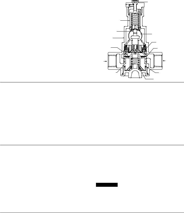
Hot and cold water supplies enter HydroGuard® XP at indicated ports (See Fig. 1) then flow past plunger and seats. Next, hot and cold water flow is directed to the mixing chamber where the thermostatic actuator is located.
Temperature adjustment screw moves the actuator to determine the discharge temperature. If discharge temperature rises due to inlet pressure or temperature, the actuator expands, decreasing flow of hot water. The reverse occurs with a drop in discharge temperature.
Cold water supply failure - causes actuator to expand forcing the plunger against the hot water seat.
In case of hot water failure cold water will flow through cold water bypass to the outlet.
|
Temperature |
|
Adjustment |
Adjustment |
Screw |
Locking Screw


Figure 1
|
Overload |
|
|
Assembly |
|
|
Thermostatic |
|
|
Actuator |
Outlet |
|
|
|
|
Body |
|
|
|
By-Pass |
|
|
Check |
|
Mixing |
Cold Water |
|
Chamber |
|
|
Seat |
|
|
|
|
Hot Water |
|
Cold Water |
|
|
|
|
Plunger |
Hot Water |
|
Seat |
|
|
|
|
|
|
Actuator Return |
|
|
Spring |
Installation Guidelines ν
1.Flush all piping thoroughly before installing.
2.The installation and field adjustment of ETV valves are the responsibility of the installer and shall be carried out in accordance with the following steps.
3.Locate ETV valve as close as possible to the fixture being supplied. It shall be accessible for testing, adjustment and/or maintenance in its installed position.
4.Shutoff valves are installed for maintenance purposes, provision shall be made to prevent unauthorized shutoff.
5.When ETV valve supplies tempered water to self-closing and/or solenoid valves, provide a shock absorber (Powers' part # 460 353) on the discharge line. This protects the ETV valve actuator from damage by water shock waves generated by the quick closing valves.
6.Consult proper medical/safety authorities for the optimum temperature for your application. Before use, check for proper discharge temperature. Reset if necessary. Valve is preset for 85°F (29°C)
Adjustment and Testing ν
1.Loosen adjustment locking screw
2.Check outlet temperature, which is factory set to 85°F (29°C). If it is not, reset it by loosening adjustment locking screw and rotating temperature adjustment screw clockwise to reduce temperature or counterclockwise to increase the outlet temperature.
3.Close cold water checkstop. Verify that flow shuts down immediately.
4.Open cold water checkstop. Close hot water checkstop. Verify adequate flow from fixture(s).
5.Open hot water checkstop, verify temperature returns to set temperature.
6.Tighten adjustment locking screw.
7.Record test data on maintenance tag which should be provided by the facility.
NOTICE
Contact Powers application department at 800.669.5430 for high temperature readjustment procedure.
Maintenance and Troubleshooting ν
What to look for if:
•The flow of water is less then desired.
a.Stop valves or supply to HydroGuard® XP not fully open.
b.Clogged checkstop strainer screens.
c.Accumulation of lime deposit around valve seats.
d.Low supply pressure or unusual supply temperature.
•The flow of water is completely shutoff.
a.Stop valves or supply valves are completely closed.
b.Valves downstream from HydroGuard® XP are fully closed.
c.Loss of cold water supply pressure
2
 Loading...