

Page 1
HYDROGUARD
®
XP Emergency Tempering Valve
Technical Instructions
!
WARNING
Read this Manual BEFORE using this equipment.
Failure to read and follow all safety and use
information can result in death, serious personal
injury, property damage, or damage to the
equipment.
Keep this Manual for future reference.
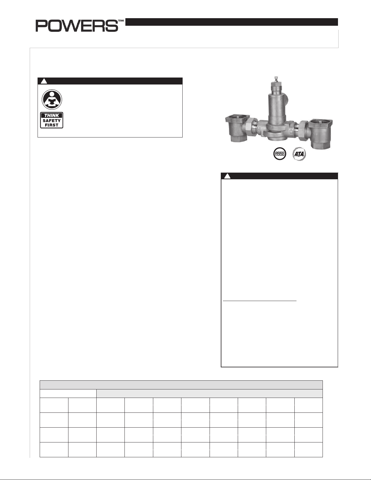
Description n
HydroGuard® XP Emergency Tempering valves thermostatically blend hot and cold
water to deliver tepid water to emergency fixtures, quickly compensating for temperature variations due to the changes in inlet temperature or pressure. Powers'
exclusive internal bypass ensures cold water flow in the event of loss of hot water.
US Patent Pending
Specifications n
Connections (NPT)
ETV200 .............................................. 3/4" inlets, 1" outlet
ETV400 .............................................. 1-1/4" inlets, 1-1/2" outlet
ETV500 .............................................. 2" inlets, 2" outlet
Maximum Operating Pressure ............................. 125psi (861 kPa)
Maximum Hot Water Temperature . ..................... 180°F (82°C)
Temperature Adjustment Range .......................... 60 - 95°F (15 - 35°C)
Factory Set Temperature* .................................... 85°F (29°C)
Bypass Flow Rate at 30psid*
ETV200 .............................................. 30 gpm (114 lpm)
ETV400 .............................................. 50 gpm (189 lpm)
ETV500 .............................................. 81 gpm (307 lpm)
Maximum Flow with Cold Water Shutoff* .......... 0.5 gpm (1.9 lpm)
Listing ........................................................................ ASSE 1071
* When tested under conditions specified in ASSE 1071 Standard
IS-P-ETV200_400_500
with Cold Water Bypass
Advanced Thermal Activation
!
WARNING
FAILURE TO COMPLY WITH PROPER INSTALLATION
AND MAINTENANCE INSTRUCTIONS COULD
CONTRIBUTE TO THE VALVE FAILURE, RESULTING IN
INJURY AND DEATH.
TO ENSURE THE ACCURATE AND RELIABLE
OPERATION OF THIS PRODUCT, IT IS ESSENTIAL TO:
• Properly size each valve based on the individual
application.
• Properly design the recirculation system to minimize
pressure and temperature variations.
• Check outlet temperature to ensure it does not
exceed 110°F (43°C). Make sure temperature limit
stop is properly reset to maximum 110°F (43°C) following valve maintenance or repair. Tampering with
limit stop in any way may result in scalding temperature causing serious bodily harm and/or death.
Periodic Inspection/Maintenance: OPERATION OF
EMERGENCY VALVES AND FIXTURES SHOULD BE
TESTED WEEKLY PER ANSI Z358.1. In addition conduct an annual maintenance program by a licensed
plumber or a qualified service technician to ensure
proper operation of the critical components. Regular
checking and cleaning of the thermostat assembly
assures proper product function. Corrosive water
conditions, temperatures over 210°F, unauthorized
adjustments or repair could render the valve ineffective for the service intended.
Capacity n
Model
ETV200
ETV400
ETV500
Flow Capacity at 85°F (29.4°C)
Pressure Drop Across Valve
Min. Flow
to ASSE 1071 (34 kPa) (69 kPa) (103 kPa) (138 kPa) (207 kPa) (310 kPa) (414 kPa)
3.0 gpm
11.4 lpm 50.7 lpm 71.9 lpm 87.8 lpm 101.4 lpm 124.5 lpm 152.2 lpm 176.0 lpm
3.0 gpm
11.4 lpm 128.7 lpm 182.0 lpm 223.0 lpm 257.4 lpm 315.0 lpm 386.1 lpm 446.7 lpm
3.0 gpm
11.4 lpm 184.3 lpm 260.8 lpm 319.5 lpm 369.1 lpm 452.0 lpm 553.4 lpm 639.4 lpm
C
6
15.2
21.8
V
5psi 10psi 15psi 20psi 30psi 45psi 60psi
13.4 gpm 19.0 gpm 23.2 gpm 26.8 gpm 32.9 gpm 40.2 gpm 46.5 gpm
34.0 gpm 48.1 gpm 58.9 gpm 68.0 gpm 83.2 gpm 102.0 gpm 118.0 gpm
48.7 gpm 68.9 gpm 84.4 gpm 97.5 gpm 119.4 gpm 146.2 gpm 168.9 gpm
Page 2
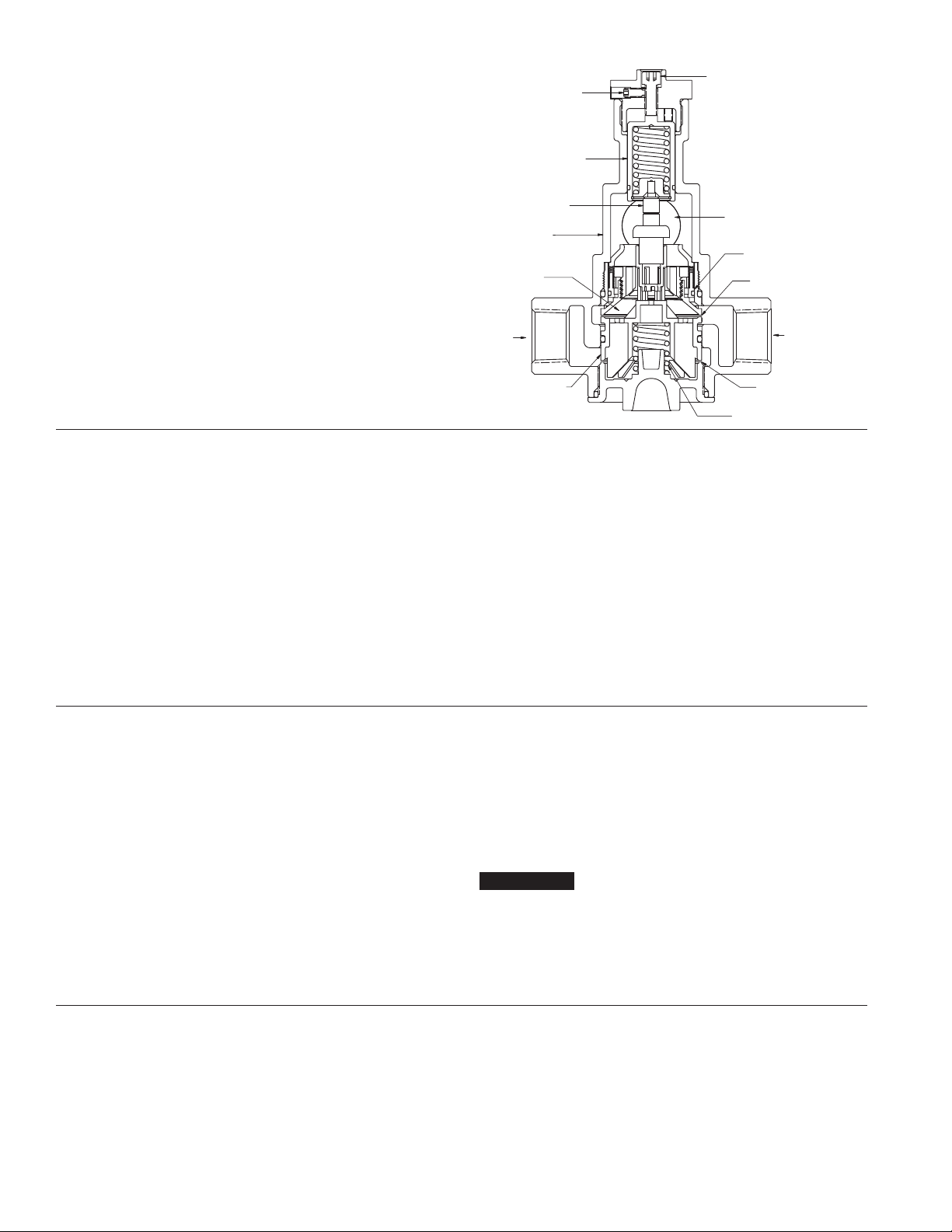
Spring
Operation n
Hot and cold water supplies enter HydroGuard® XP at indicated ports
(See Fig. 1) then flow past plunger and seats. Next, hot and cold water
flow is directed to the mixing chamber where the thermostatic actuator
is located.
Temperature adjustment screw moves the actuator to determine the
discharge temperature. If discharge temperature rises due to inlet
pressure or temperature, the actuator expands, decreasing flow of hot
water. The reverse occurs with a drop in discharge temperature.
Cold water supply failure - causes actuator to expand forcing the plunger against the hot water seat.
In case of hot water failure cold water will flow through cold water
bypass to the outlet.
Thermostatic
Mixing
Chamber
Adjustment
Locking Screw
Overload
Assembly
Actuator
Body
Temperature
Adjustment
Screw
Outlet
By-Pass
Check
Cold Water
Seat
Figure 1
Installation Guidelines n
1. Flush all piping thoroughly before installing.
2. The installation and field adjustment of ETV valves are the responsibility of the installer and shall be carried out in accordance with the
following steps.
3. Locate ETV valve as close as possible to the fixture being supplied.
It shall be accessible for testing, adjustment and/or maintenance in
its installed position.
4. Shutoff valves are installed for maintenance purposes, provision
shall be made to prevent unauthorized shutoff.
Adjustment and Testing n
1. Loosen adjustment locking screw
2. Check outlet temperature, which is factory set to 85°F (29°C). If it
is not, reset it by loosening adjustment locking screw and rotating
temperature adjustment screw clockwise to reduce temperature or
counterclockwise to increase the outlet temperature.
3. Close cold water checkstop. Verify that flow shuts down immediately.
4. Open cold water checkstop. Close hot water checkstop. Verify
adequate flow from fixture(s).
Hot Water
Seat
Cold Water
Hot Water
Plunger
Actuator Return
5. When ETV valve supplies tempered water to self-closing and/or solenoid valves, provide a shock absorber (Powers' part # 460 353) on the
discharge line. This protects the ETV valve actuator from damage by
water shock waves generated by the quick closing valves.
6. Consult proper medical/safety authorities for the opti-
mum temperature for your application. Before use,
check for proper discharge temperature. Reset if necessary. Valve is preset for 85°F (29°C)
5. Open hot water checkstop, verify temperature returns to set temperature.
6. Tighten adjustment locking screw.
7. Record test data on maintenance tag which should be provided by
the facility.
NOTICE
Contact Powers application department at 800.669.5430 for
high temperature readjustment procedure.
Maintenance and Troubleshooting n
What to look for if:
• The ow of water is less then desired.
a. Stop valves or supply to HydroGuard
b. Clogged checkstop strainer screens.
c. Accumulation of lime deposit around valve seats.
d. Low supply pressure or unusual supply temperature.
®
XP not fully open.
• The ow of water is completely shutoff.
a. Stop valves or supply valves are completely closed.
b. Valves downstream from HydroGuard
c. Loss of cold water supply pressure
2
®
XP are fully closed.
Page 3

Disassembly and Inspection n
Due to the safety nature of this product, we recommend
removal of the valve by a licensed contractor and full
inspection of all components whenever the valve is disas-
sembled for any reason. Temperature must be checked and
adjusted. For temperature adjustment see Adjustment &
Testing section.
Disassembly
1. Close supply valves and/or checkstops
2. Remove valve from its outlet piping. Work should be performed on a
clean table or workbench.
3. To remove thermal actuator from top
a) Loosen adjustment locking setscrew.
b) Remove bonnet and overload assembly.
c) Lift out thermal actuator.
d) Assemble in reverse order
4. To remove the plunger assembly from bottom
a) Remove the bottom cap.
!
CAUTION
Spring is under tension.
b) Pull out spring
Parts List n
ETV 200
ETV 400
1
2
3
c) Pull out plunger using a pair of pliers.
d) Reassemble in reverse order.
NOTICE
After reassembling go back to thermal actuator section and make sure it
is sitting in its holder properly.
Inspection
1. Inspect body for any damage, deposits or pitting. Clean or replace as
necessary.
2. Check the actuator for proper operation at room temperature. Hold
actuator between your finger and thumb. Apply force on end of stem.
Measure the entire length of the actuator and then place it in the hot
water (105-110°F) for 10 seconds. Actuator stem should extend at
least 1/8" longer than when at room temperature.
ETV 500
1
2
3
7
4
5
6
Index Description
Part No.
ETV200 ETV400
1 Temperature Adjustment Screw 390 777 390 787
2 Adjustment Locking Screw 390 795 390 795
3 Actuator 390 808 390 810
4 Plunger Kit 390 802 390 803
5 Spring 390 620 390 162
6 O-Ring 1101575 2101003
7 Checkstop Rebuild Kit 390 800 390 801
7
4
5
6
ETV500
Index Description Part No.
1 Temperature Adjustment Screw 390 787
2 Adjustment Locking Screw 390 795
3 Actuator Kit 390 815
4 Plunger Kit 390 816
5 Spring 390 162
6 O-Ring 2101003
7 Checkstop Rebuild Kit 390 811
3
Page 4

WARNING: This product contains chemicals known to the
State of California to cause cancer and birth defects or
other reproductive harm.
For more information: www.watts.com/prop65
Warranty n
The Seller warrants that the equipment manufactured by it and covered by this order or contract is free from defects in material and workmanship and, without
charge, equipment found to be defective in material or workmanship will be repaired, or at Seller’s option replaced F.O.B. original point of shipment, if written
notice of failure is received by Seller within one (1) year after date of shipment (unless specifically noted elsewhere), provided said equipment has been properly
installed, operated in accordance with the Seller’s instructions, and provided such defects are not due to abuse or decomposition by chemical or galvanic action.
THIS EXPRESS WARRANTY IS IN LIEU OF AND EXCLUDES ALL OTHER WARRANTIES, GUARANTEES, OR REPRESENTATIONS, EXPRESS OF IMPLIED. THERE ARE
NO IMPLIED WARRANTIES OF MERCHANTABILITY OR OF FITNESS FOR A PARTICULAR PURPOSE. The Seller assumes no responsibility for repairs made on the
Seller’s equipment unless done by the Seller’s authorized personnel, or by written authority from the Seller. The Seller makes no guarantee with respect to material
not manufactured by it.
A Watts Water Technologies Company
USA: Phone: 1.800.669.5430 • Fax 1.847. 229.0526 • www.powerscontrols.com
Canada: Phone: 1.888.208.8927 • Fax 1.888. 479.2887 • www.powerscontrols.ca
IS-P-ETV200_400_500 1329 EDP# 6512323 © Powers 2013
 Loading...