

Page 1
HydroGuard
With Internal & External Cold Water Bypass
Technical Instructions
Description ■
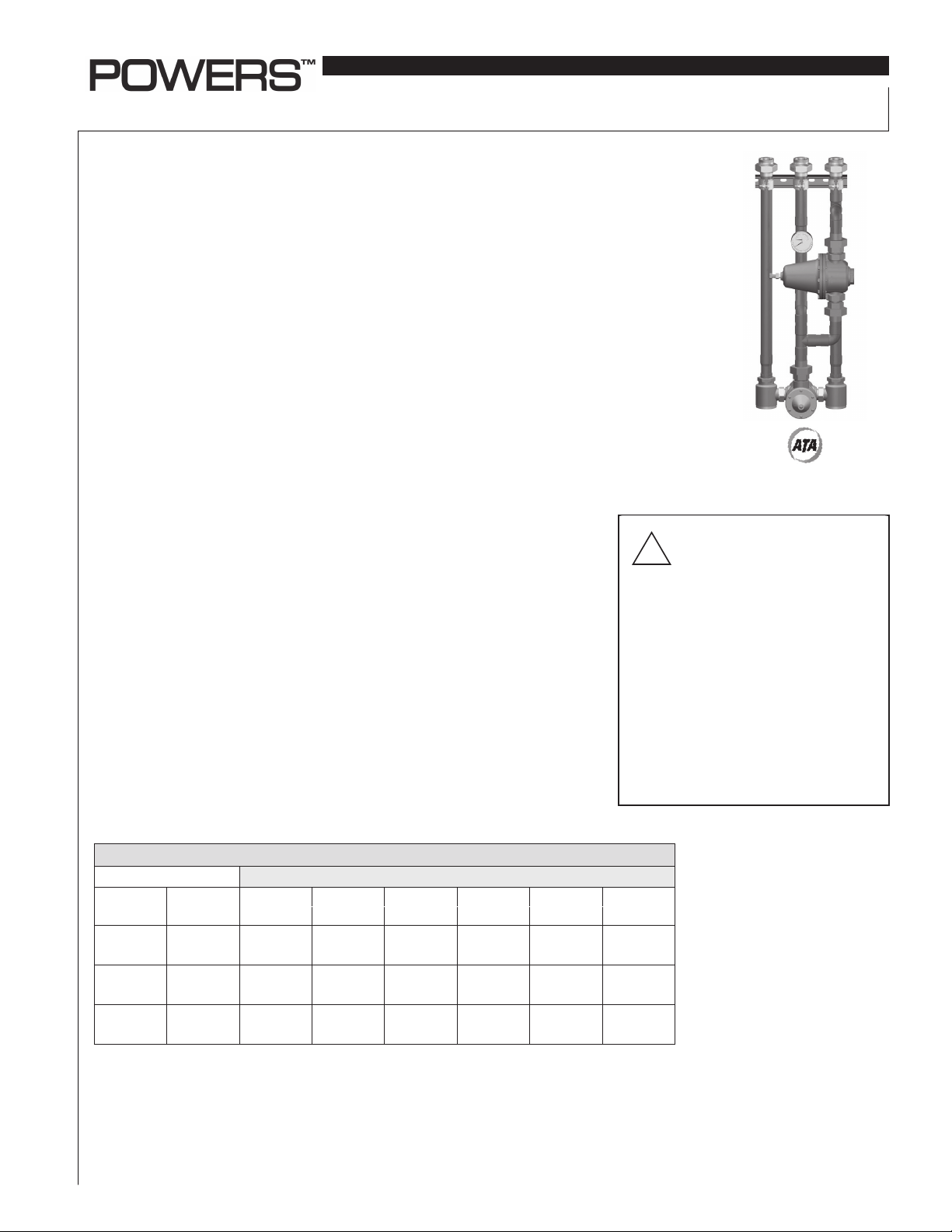
Powers external bypass emergency tempering valve system consists of Powers ES
Series emergency tempering valve and an independent external cold water bypass.
Under normal operation the valve will thermostatically blend hot and cold water to
deliver tepid water to emergency fi xtures, quickly compensating for temperature
variations due to changes in inlet temperature.
Powers ES Series valves have a dual internal cold water bypass that ensures cold
water fl ow in the event of valve failure or loss of hot water. In many applications,
the internal cold water bypass capacity is adequate to provide proper operation of
the emergency fi xtures.
The external cold water bypass system ensures an adequate supply of cold water
if the primary valve, under a hot water supply loss or other failure mode, lacks the
volume necessary for the proper operation of the emergency fi xture.
Powers external bypass emergency tempering valve system includes a pressure
regulating valve that will open when the outlet pressure decreases to a level that
indicates a lack of water caused by a failure mode.
Specifi cations ■
Maximum Operating Pressure . . . . . . . . . . . . . . 125psi (861 kPa)
Maximum Hot Water Temperature . . . . . . . . . . 180°F (82°C)
Approach Temperature . . . . . . . . . . . . . . . . . . . . 15°F (8°C) Above Set Point
Temperature Adjustment Range . . . . . . . . . . . . 60 - 95°F (15 - 35°C)
Factory Set Temperature . . . . . . . . . . . . . . . . . . 85°F (29°C)
Compliance . . . . . . . . . . . . . . . . . . . . . . . . . . . . . . ANSI Z 358-1 1998
Note: Set point cannot be less than the cold water temperature. For best operation, hot and
cold water should be at least 15°F (8°C) from desired set point.
IS-P-ES150-200-400XBY
®
Series Tempering Valve
Advanced Thermal Activation
WARNING: TO ENSURE THE
ACCURATE AND RELIABLE
!
OPERATION OF THIS PRODUCT, IT IS
ESSENTIAL TO:
• Properly size each valve based on the individual application.
• Properly design the recirculation system to
minimize pressure and temperature variations.
• Conduct an annual maintenance program to
ensure proper operation of all critical components.
FAILURE TO COMPLY WITH PROPER
INSTALLATION INSTRUCTIONS COULD
CONTRIBUTE TO VALVE FAILURE, RESULTING
IN IN JURY OR DEATH.
Capacity ■
Flow Capacity at 50-50 Mixed Ratio
Pressure Drop Across Valve
Model
ES150XBY
ES200XBY
ES400XBY
*Minimum fl ow when emergency bypass valve is installed at or near hot water source with recirculating tempered water with a properly sized continuously operating recirculating pump.
Min. Flow
Rate*
1.0 gpm 4.0 gpm 6.0 gpm 9.0 gpm 14.0 gpm 17.0 gpm 20.0 gpm
3.8 lpm 15.2 lpm 22.7 lpm 34.1 lpm 53.0 lpm 64.4 lpm 75.8 lpm
3.0 gpm 15.0 gpm 20.0 gpm 30.0 gpm 36.0 gpm 45.0 gpm 52.0 gpm
11.0 lpm 57.0 lpm 76.0 lpm 113.0 lpm 136.0 lpm 170.0 lpm 197.0 lpm
3.0 gpm 27.0 gpm 38.0 gpm 54.0 gpm 66.0 gpm 80.0 gpm 92.0 gpm
11.0 lpm 102.0 lpm 144.0 lpm 203.0 lpm 249.0 lpm 305.0 lpm 352.0 lpm
5psi 10psi 20psi 30psi 45psi 60psi
(34 kPa) (69 kPa) (138 kPa) (207 kPa) (310 kPa) (414 kPa)
Cold Water Bypass Capacity* ■
ES150XBY . . . . . . . . . . . . . . . . . . . . . . . . . 10.0 gpm (37.8 lpm) @ 30psi (207 kPa)
ES200XBY . . . . . . . . . . . . . . . . . . . . . . . . 36.0 gpm (136.3 lpm) @ 30psi (207 kPa)
ES400XBY . . . . . . . . . . . . . . . . . . . . . . . . 52.0 gpm (196.8 lpm) @ 30psi (207 kPa)
* Flow capacity measured with 60psi (414 kPa) cold water supply pressure.
Page 2
Prior to Installation ■
E
1. Flush all piping thoroughly before installing.
2. Locate HydroGuard
3. Consult proper medical/safety authorities for the optimum
temperature for your application. Before use, check for proper
discharge temperature. Reset if necessary. Valve is preset for
85°F (29°C)
®
as close as possible to the fi xture being supplied
Temperature Adjustment ■
1. Open emergency fi xture to allow fl ow through HydroGuard
2. Loosen adjustment locking setscrew on the side of the orange top
3. Use special wrench (provided with the valve) to adjust the discharge tempered water. Place wrench at temperature adjustment screw. Turn screw counterclockwise to full hot position
4. Turn clockwise to desired temperature. Allow valve temperature
to settle before making next adjustment.
5. When desired temperature is set, tighten the adjustment locking screw. Remove special wrench and keep in a safe place for
future use
6. Close emergency fi xtures
®
Adjustment of Cold Water Bypass ■
1. Open emergency fi xture
2. Close hot water checkstop
3. Verify there is adequate fl ow at the emergency fi xture
4. If there is less fl ow than required, adjust cold water bypass fl ow
as follows:
a) Loosen the locknut at the top of the cold water bypass. This
must be all the way out to allow full range of adjustment
b) To increase bypass fl ow, turn adjusting screw clockwise or
turn counterclockwise to reduce fl ow
NOTE: Improper setting of cold water bypass may lead to con-
tinuous cold water fl ow that will effect tempered water setting.
c) Once proper fl ow conditions are set, tighten the locknut
d) Open hot water checkstop
NOTE: For any problems, refer to Troubleshooting section of this
document or contact Powers' Technical Support Department at
1.800.669.5430 or info@powerscontrols.com.
PART LIST FOR VALVE ■
See TI ES150 or TI ES200/ES400
Troubleshooting ■
What to look for if:
• The fl ow of water is less then desired:
1. Checkstops are not fully open
2. Clogged checkstop strainer screen
3. Accumulation of lime deposits around the valve
4. Low supply pressure or unusual supply temperature
5. Bypass valve not open. Refer to adjustment of cold water
bypass instructions
• The fl ow of water is completely shut off:
1. Checkstops are not fully open
2. Fixtures downstream of HydroGuard
®
are fully closed
3. Loss of cold water supply
• The tempered water is too cold:
1. Refer to temperature adjustment instructions
2. Make sure hot and cold water are at least 15°F (8°C) from
desired set point
3. Cold water bypass incorrectly set
Preventative Maintenance ■
Emergency tempering valves are control devices which must be
cleaned and maintained on a regular basis.
1. Test HydroGuard
a) Open all fi xtures and verify tempered water is still at set point
b) Verify fl ow rate is adequate at fi xture
c) Shut cold water checkstop to verify that fl ow through mixing
valve shuts down immediately
e) Open cold water checkstop and shut hot water checkstop.
Verify adequate fl ow from fi xtures. If not, refer to adjustment
of cold water bypass instructions.
f) Open hot water checkstop. Verify temperature returns to set
point.
2) Before servicing checkstops or piping, turn off the water
upstream. At least every twelve (12) months open up the
checkstops and check for the free movement of the poppet.
3) Before servicing the valve, turn off the water supply upstream
or close the checkstops. To close the checkstops, turn the
adjusting screw clockwise.
4) When opening checkstops after servicing, turn adjusting screw
counterclockwise to fully open position then turn adjusting
screw 1/2 turn clockwise for fi nal setting
5) Every three (3) months, check the maximum temperature adjust-
ments.
6) Every twelve (12) months, remove the valve bonnets and check
the internal components for freedom of movement.
®
system every week:
CAUTION: Any changes in supply
condition could effect the outlet water
!
temperature. Check and adjust the
valves accordingly to prevent injury to the users.
Warranty ■
The Seller warrants that the equipment manufactured by it and covered by this order or contract is free from defects in material and workmanship and, without
charge, equipment found to be defective in material or workmanship will be repaired, or at Seller’s option replaced F.O.B. original point of shipment, if written
notice of failure is received by Seller within one (1) year after date of shipment (unless specifically noted elsewhere), provided said equipment has been properly
installed, operated in accordance with the Seller’s instructions, and provided such defects are not due to abuse or decomposition by chemical or galvanic action.
THIS EXPRESS WARRANTY IS IN LIEU OF AND EXCLUDES ALL OTHER WARRANTIES, GUARANTEES, OR REPRESENTATIONS, EXPRESS OF IMPLIED. THERE AR
NO IMPLIED WARRANTIES OF MERCHANTABILITY OR OF FITNESS FOR A PARTICULAR PURPOSE. The Seller assumes no responsibility for repairs made on the
Seller’s equipment unless done by the Seller’s authorized personnel, or by written authority from the Seller. The Seller makes no guarantee with respect to materia
not manufactured by it.
USA: Phone: 1.800.669.5430 • Fax 1.847. 229. 0526 • www.powerscontrols.com
Canada: Phone: 1.888.208.8927 • Fax 1.888.479.2887 • www.powerscontrols.ca
IS-P-ES150-200-400XBY 0826 EDP# 6512315 © 2008 Powers
 Loading...