

Page 1
The Series ES Hydroguard thermostatically blends hot and cold
water to deliver tepid water to emergency fixtures, quickly
compensating for temperature variations due to changes in inlet
temperature or pressure. Powers’ exclusive Dual Internal
By-Pass* ensures cold water flow in the event of a valve failure
or loss of hot water.
* US Patent 6,575,377
DESCRIPTION
WARNING: TO INSURE THE ACCURATE AND RELIABLE
OPERATION OF THIS PRODUCT, IT IS ESSENTIAL TO:
• Properly size each valve based on the individual application
• Properly design the recirculation system to minimize pressure
and temperature variations
• Conduct an weekly maintenance program to insure proper
operation of all critical components
FAILURE TO COMPLY WITH PROPER INSTALLATION
INSTRUCTIONS COULD CONTRIBUTE TO VALVE FAILURE,
RESULTING IN INJURY OR DEATH.
TECHNICAL INSTRUCTIONS
Hydroguard®ES Series Emergency Tempering Valves
with Dual Internal Cold Water By-Pass
ES200 and ES400
Form TI ES200/ES400 v2
Table 1, Capacity Tables, present the Hydroguard discharge capacity
in gpm and Ipm for various pressure differentials (the difference
between the lowest inlet pressure and the discharge pressure at the
Hydroguard).
SIZING
Operating
Maximum Pressure. . . . . . . . . . . . . . . . . . . . . . 125 psig (861.25 kPa)
Maximum Hot Water Temperature . . . . . . . . . . . . . . . . . 180°F (82°C)
Approach Temperature . . . . . . . . . . . . . . . . . . . . . . . . . . . . 15°F (8°C)
Temperature Adjustment Range . . . . . . . . 60°F (15°C) - 95°F (35°C)
Factory Set Temperature . . . . . . . . . . . . . . . . . . . . . . . . 85°F (29°C)
Compliance. . . . . . . . . . . . . . . . . . . . . . . . . . . . . ANSI Z358.1 1998
Note: Set point cannot be less than the cold water temperature. For best
operation, hot and cold water should be at least 15
°F (9.4°C) from desired set
point.
SPECIFICATIONS
Table 1- Capacity Tables
Flow Capacity in US gpm at 50-50 Mixed Ratio
Model Min. Flow Pressure Drop Across Valves in psi
Rate 5 10 20 30 45 60 75
ES200 3.0 gpm 15 20 30 36 45 52 58
ES400 3.0 gpm 27 38 54 66 80 93 104
Flow Capacity in lpm at 50-50 Mixed Ratio
Model Min. Flow Pressure Drop Across Valves in kP
A
Rate 34 69 138 207 310 414 517
ES200 11.0 lpm 57 76 113 136 170 197 220
ES400 11.0 lpm 102 144 203 249 305 352 393
By-Pass flows will vary depending on supply conditions and application.
Model ES400
Typical Flow
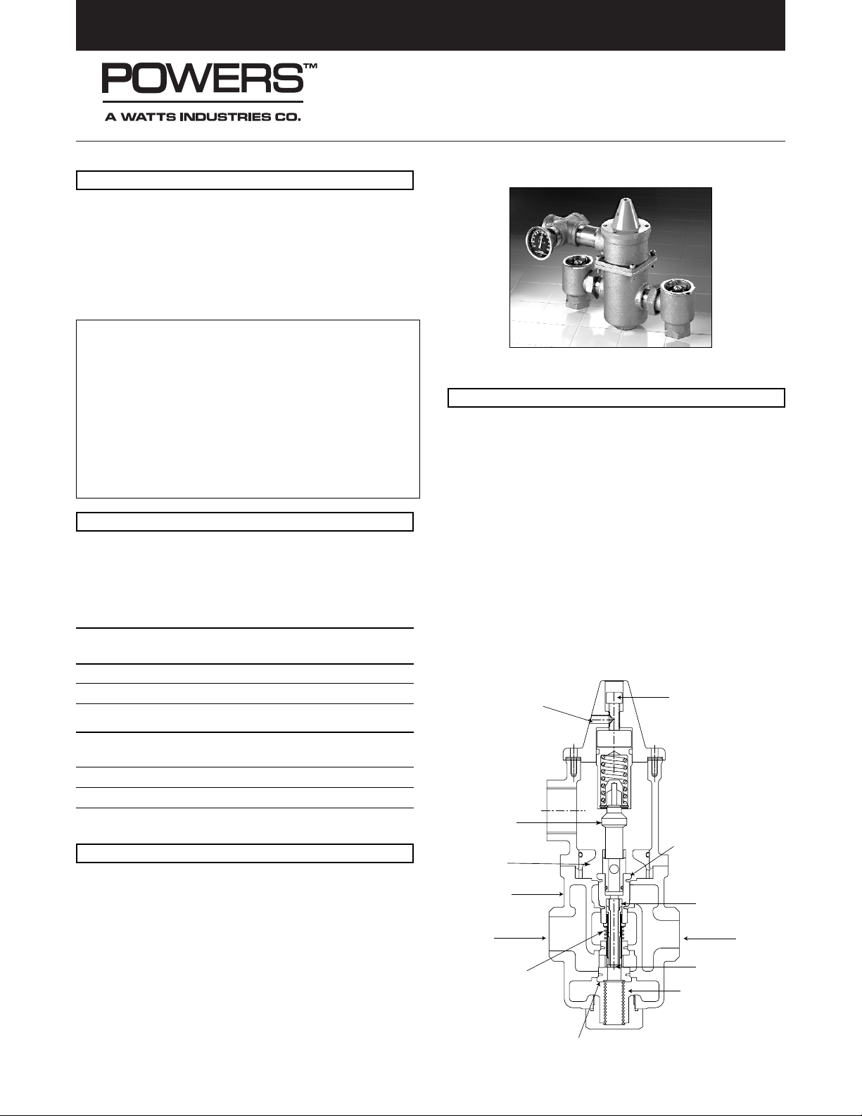
Hot and cold water supplies enter Hydroguard at indicated ports,
(see Figure 1) then flow past their respective balanced poppet plug
and seats. Next, hot and cold water flow is directed to the mixing
chamber where the thermostatic actuator is located.
Temperature adjustment screw moves the actuator/poppets to
determine the discharge temperature.
With a rise in discharge temperature due to pressure or temperature fluctuation on the inlet, the actuator expands, decreasing hot
water and increasing cold water flow to maintain the valve set
point. The reverse occurs with a drop in discharge temperature.
• Cold water supply failure – causes actuator to expand allowing
the motor to seat hot water poppet.
• Hot water supply pressure failure – causes actuator to contract
opening cold water bypass ports. Secondary bypass mechanism opens upon failure of actuator or hot water.
OPERATION
Mixing
Chamber
Body
Balanced Hot
Water Poppet
Hot Water
Primary
By-Pass
Spring
Secondary
By-Pass
Temperature
Adjustment
Screw
Adjustment
Locking
Screw
Thermostatic
Actuator
Cold Water
By-Pass Ports
Cold Water
Balanced Cold
Water Poppet
Motor
Return
Spring
Figure 1
Page 2
TI ES200/ES400 v2 Page 2
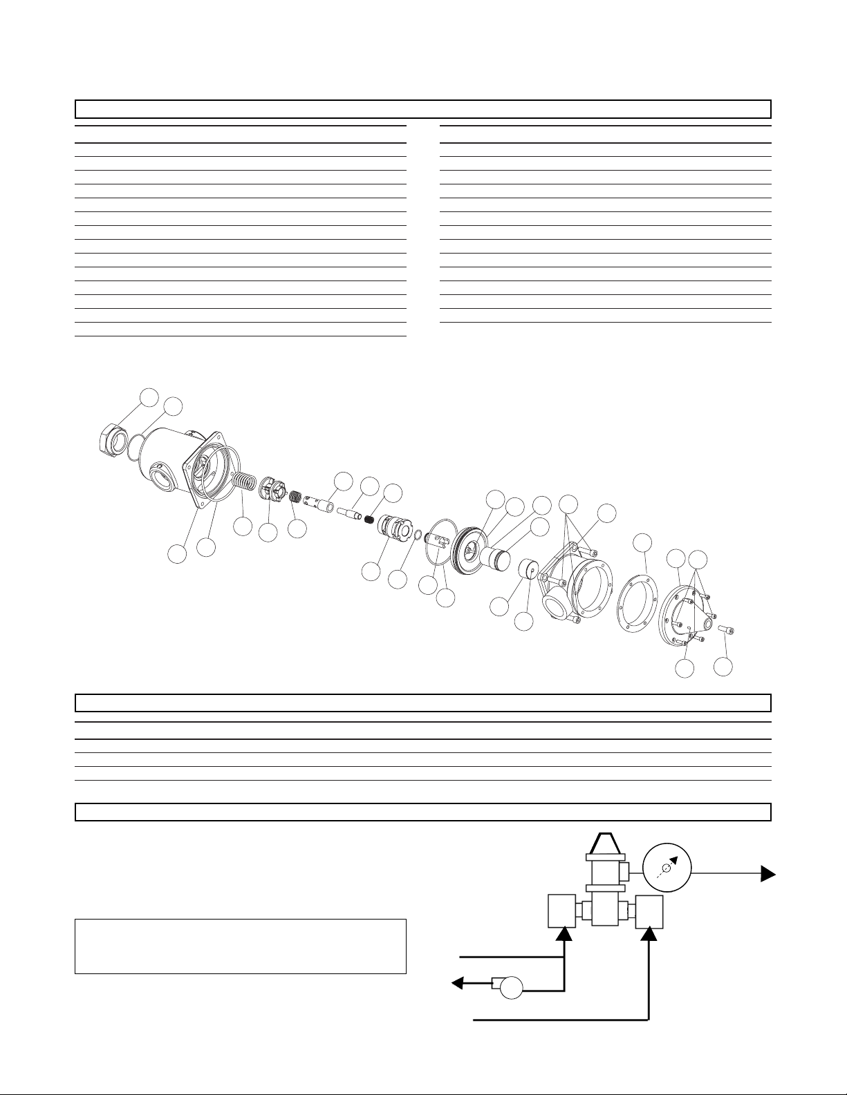
TAG DESCRIPTION
1 Etched Bonnet
2 Adjustment Screw
3 Bonnet Screw
4 Set Screw
5 Bonnet Gasket
6 Motor Housing
7 Housing Bolt
8 Temp Limit Spacer
9 Spacer Set Screw
10 Overload Assy
11 Overload “O” Ring
12 Funnel
13 Thermal Actuator
14 Funnel “O” Ring
TAG DESCRIPTION
15 Motor Adapter
16 Motor Adapter “O” Ring
17 Hot Water Poppet
18 Pressure Relief Spring
19 Pressure Relief Poppet
20 CW Bypass Plug
21 Bypass Spring
22 Cold Water Poppet
23 Return Spring
24 Body “O” Ring
25 Body
26 Body Cap “O” Ring
27 Body Cap
ES200 KIT NUMBER ES400 KIT NUMBER DESCRIPTION CONTAINS ITEMS:
390-573 390-574 Actuator Replacement Kit 5,13,15,16,24
390-575 390-576 Poppet Replacement Kit 15-24,26
390-577 390-578 Gasket and “O” Ring Kit 5,11,14,16,24,26
27
26
25
24
23
22
21
20
19
18
17
16
15
14
13
12
11
10
9
2
1
6
3
4
8
7
5
PARTS LIST
REPAIR KITS
RECIRCULATION
The mixing valve should be mounted as close as possible to
the fixture(s) that it serves.
If the valve is some distance from the hot water source, recirculation may be required to keep the hot water supply within
specified limits.
CAUTION: Use care in installing the cold water line such
that it does not pass through areas with high ambient
temperatures or become exposed to direct sunlight.
Powers ES Series
Tempering Valve
Hot Water Recirculation
Tempered Water
to Fixtures
Cold Water
Hot Water Return
Hot Water
H
C
Page 3

TI ES200/ES400 v2 Page 3
CALIFORNIA PROPOSITION 65 WARNING
WARNING: This product contains chemicals known to the State of
California to cause cancer and birth defects or other reproductive
harm.
(Installer: California law requires that this warning be given to the
consumer.)
For more information: www.wattsind.com/prop65
What to look for if:
• The flow of water is less than desired.
a. Stop valves or supply to Hydroguard not fully open.
b. Clogged checkstop strainer screens.
c. Accumulation of lime deposits around valve seats.
d. Low supply pressures or unusual supply temperatures.
• The flow of water is completely shut off.
a. Stop valves or supply valves are completely closed.
b. Valves downstream from Hydroguard fully closed.
c. Loss of cold water supply pressure.
MAINTENANCE AND TROUBLESHOOTING
5. Remove four (4) body screws and carefully remove lower
body.
6. Slide out hot water poppet and bypass assembly.
7. Loosen plug on bottom of lower body. Remove plug,
spring, and cold water poppet.
CAUTION: The plug is under spring pressure.
Use care when removing.
8. Remove the “O” rings from the body.
• Inspection:
1. Inspect the body for any damage, deposits, or pitting -
clean or replace as necessary.
2. Check the poppets, springs, and bypass assembly for any
damage, deposits, or pitting. If any component appears
stuck, worn, or damaged, replace all the internal
parts.
3. Check the actuator for proper operation. Measure and
note the entire length of the actuator at room temperature
or mark the stem with a piece of tape. Place the actuator
in hot water (105-115
°F) for one (1) minute. Measure the
length of the actuator. Actuator should be at least 1/8"
longer than when at room temperature.
DISASSEMBLY AND REPAIR INSTRUCTIONS
INSTALLATION INSTRUCTIONS
1. IMPORTANT: Flush all piping thoroughly before installing.
2. Locate the Hydroguard as close as possible to the fixture
being supplied.
Note: Remove body screws to turn outlet to any of four
positions. The Hydroguard body can be rotated to any
position due to the union inlets. Install thermometer in
discharge using supplied fittings.
Make certain the body screws and unions are tightened
securely to prevent leakage.
3. CAUTION: When the Hydroguard supplies tempered water to
self-closing and/or solenoid valves, provide a shock
absorber (Powers Part No. 460-353) on the discharge line.
This protects the Hydroguard thermostatic motor from damage by water shock waves generated by the quick closing
valves.
4. Consult proper medical/safety authorities for the opti-
mum temperature for your application. Before use, check
for proper discharge temperature. Reset if necessary.
Valve is preset for 85
°F (29.4°C).
ADJUSTMENT AND TESTING
1. Replace adjustment screw and set to proper
temperature. Open all fixtures and verify all outlet
temperature is adequate.*
2. Verify adequate flow rate from fixtures.
3. Close the cold water checkstop. Verify that flow shuts
down immediately.
4. Open cold water checkstop, and close hot water
checkstop. Verify adequate flow from fixture(s).
5. Open hot water checkstop, verify temperature returns to
set temperature.
6. Record test data on maintenance tag which should be
attached to the valve.
*Contact factory for high temperature readjustment
procedure.
Consult proper medical/safety authorities for optimum
temperature for your application. Before use, check
for proper discharge temperature. Reset if necessary.
Per ANSI Z358.1-1998, Emergency fixtures should
be tested weekly. Any unit failing any of the above
tests should be repaired or replaced immediately.
Due to the safety nature of this product, we recommend removal
of the valve and a full inspection of all components whenever the
valve is disassembled for any reason.
• Disassembly:
1. Close supply valves and/or checkstops. Take apart unions
between the valve and the checkstops.
2. Remove valve from its outlet piping. Work should be
performed on a clean table or workbench. Use caution
when disassembling the valve as there are several
small springs and parts inside.
3. Remove bonnet screws with a 3/15" hex wrench.
4. Remove bonnet and actuator.
Page 4

TI ES200/ES400 v2 Page 4
Insert the cold water poppet, spring,
and plug into the bottom of the
lower housing.
Carefully insert the bypass assembly into the body.
Install the hot water poppet using
care not to disturb the springs or
bypass assembly.
REASSEMBLY
Lubricate the body “O” ring, and
place in groove on body. Tighten
housing bolts.
Place actuator into motor adaptor
Install bonnet onto valve with 43/16” screws.
Form TIES200/ES400 v2 0335 EDP # 6508880 Printed in USA
© 2003 Powers, a Watts Industries Co.
USA Phone: 1.800.669.5430 • Fax 1.877.459.3440
Canada Phone: 1.888.208.8927 • Fax 1.888.882.1979
www.powerscontrols.com
 Loading...