

Powers HydroGuard T/P e705, e700 Series, HydroGuard T/P e707, HydroGuard T/P e710 Technical Instructions
Page 1

Technical Instructions
!
WARNING
Read this Manual BEFORE using this equipment.
Failure to read and follow all safety and use
information can result in death, serious personal
injury, property damage, or damage to the
equipment.
Keep this Manual for future reference.
Description n
The Series e700 HydroGuard T/P automatically mixes hot and
cold water to deliver blended water within a specified range.
Using an advanced thermal actuator, the Series e700 quickly
compensates for temperature fluctuations induced by water
temperature and pressure changes. In the event of cold
water failure, the thermostatic motor virtually shuts off the
flow of hot water. HydroGuard T/P meets the most stringest
performance criteria for temperature and pressure changes,
defined by ASSE 1016 (Type T/P).
Featuring heavy, cast-brass construction and an adjustable
brass to brass high limit temperature stop, self-contained
IS-P-e700
HydroGuard
®
T/P
Series e700
e705
e707
e710
cartridge, corrosion resistant internal component, integral
checks, and back to back shallow wall installation capability. All parts of the e700 Series valve are accessible from
the front of the valve. All Series e700 valves open in the cold
water position to ensure maximum bather safety and comfort.
The accuracy, reliability and water economy of the Series
e700 HydroGuard T/P make it preferable for applications that
require precise, consistent water
control: showers, baths, hospital hydrotherapy and
residential areas. All e700 valves meet the Americans with
Disabilities Act (ADA).
Specifications n
Valve Construction: Combination mixing valve, with heavy cast bronze body and brass stem. Concealed adjustable high
temperature limit stop. Available with ADA-compliant ABS or metal lever handle.
Connections . . . . . . . . . . . . . . . . . . . . . . . . . . . . . . . . . . . . . . . . . 1/2" Sweat Inlet/Outlet
Capacity . . . . . . . . . . . . . . . . . . . . . . . . . . . . . . . . . . . . . . . . . . . 4 gpm
Maximum Hot Water Supply Temperature . . . . . . . . . . . . . . . . . . . . . . . 190°F(88°C)
Minimum Hot Water Supply Temperature (Approach Temperature) . . . . . . . . 10°F (5.5°C) above set point
Maximum Operating Pressure . . . . . . . . . . . . . . . . . . . . . . . . . . . . . . 125 psig (862 kPa)
Temperature Ranges (for +/- 3°F performance) . . . . . . . . . . . . . . . . . . . . . ASSE 1016 Type T/P: 90 - 110°F (32 - 43°C)
ASSE 1016 Type T: 80 - 120°F (27 - 49°C)
High Temperature Limit Stop . . . . . . . . . . . . . . . . . . . . . . . . . . . . . . . . Adjustable (factory set at 110°F [43°C])
Maximum Static Pressure . . . . . . . . . . . . . . . . . . . . . . . . . . . . . . . . . 125 psig (862kPa)
Minimum Flow . . . . . . . . . . . . . . . . . . . . . . . . . . . . . . . . . . . . . . . . 1.0 gpm (3.781 L/min)
Approved Standards . . . . . . . . . . . . . . . . . . . . . . . . . . . . . . . . . . . . CSA B125.1, ASME 112.18.1 ASSE 1016 T/P
Listing . . . . . . . . . . . . . . . . . . . . . . . . . . . . . . . . . . . . . . . . . . . . . ASSE 1016, IAPMO cUPC
Shipping Weight . . . . . . . . . . . . . . . . . . . . . . . . . . . . . . . . . . . . . . . 3.5 lbs. (1.6 kg)
All HydroGuard T/P Series e700 combination mixing valves
meet above performance specifications based on typical
operating conditions as stated in ASSE 1016 (45 psi pressure
differential, hot water supply between 140°-180°F (60°-82°C),
cold water supply less than 70°F (21°C).
If your operating conditions vary from those stated in the
standard, performance may vary as well. Consult your local
sales representative or a Powers factory engineer to discuss
your specific application. All Powers thermostatic mixing
valves perform to the requirements of standards ASSE 1016
and CSA B125.
Page 2
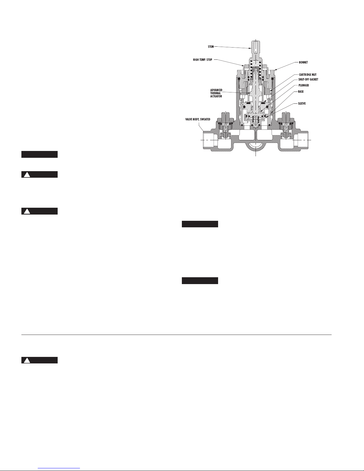
Operation n
Hot and cold water enter respective ports in the valve and mix
in a chamber containing an advanced thermal actuator (refer to
cutaway view). This actuator controls the position of the plunger
and temperature.
Rotating the adjustment handle repositions the plunger in the
cartridge assembly to produce the desired temperature. The
mixed water passes over the shut-off disc to the outlet. If the
hot or cold supply water temperature or pressure changes, the
thermal actuator will contract or expand. This movement repositions the plunger to maintain the desired temperature. With the
adjustment handle in full clockwise (OFF) position, the shut-off
disc closes the mixing chamber from the outlet.
A high temperature limit stop restricts the movement of the
control handle. All HydroGuard T/P e700 valves are factory set
to deliver tempered water up to 110°F [43°C] with equal supply
pressures, with hot water temperature 140°F [60°C], cold water
temperature 60°F [15.6°C].
NOTICE
The handle rotation stop must be adjusted by the installer.
!
WARNING
Maximum Temperature Setting/Handle Rotation Stop
The handle rotation setting must be adjusted to limit the distance
the user can rotate the handle towards the full hot water position.
!
CAUTION
Any repair or modification of the valve may affect the high temperature setting. The maximum
temperature setting must be checked by the installer before use.
1. Remove the valve handle and sleeve.
2. Adjust the valve to the desired maximum outlet temperature
[110°F (43°C) max]. Screw on the high temp. limit stop until it
touches the stem shoulder.
3. Turn the stem clockwise until the water stops.
Open valve to full hot position and verify maximum outlet
temperature setting.
4. Place sleeve "O" Ring on the bonnet shoulder.
Slide sleeve over the "O" Ring until it stops.
5. Replace handle.
Reversed Inlets
Valve is factory-set for standard inlets If reversed inlets are
required due to back-to-back installation (Cold water supply on
the left and Hot water supply on the right), follow instructions a
through d below:
a. Connect cold inlet to hot port (“H”) and hot inlet to cold port
(“C”).
NOTICE
Do not turn valve upside down. If valve is upside down, water
will not flow properly through tub spout or showerhead.
b. Turn water off with checkstops, remove bonnet and
cartridge.
c. Reinstall cartridge. “H” on the cold side of the valve body
and “C” should be on the hot side of the valve body.
d. Reinstall bonnet with high temperature limit stop on it.
NOTICE
Be certain that valve opens in full cold!
e. Hot and Cold inlets should be re-identified for reversed inlets
to avoid confusion during future maintenance.
Preventive Maintenance n
!
WARNING
Before servicing checkstops or piping, always turn off the
upstream water supply.
EVERY 12 MONTHS:
•Openupthecheckstopsandcheckforfreemovementofthe
poppet. To access the checkstops, remove the handle assembly and trim plate.
•Beforeservicingthevalve,turnoffthewatersupplyupstream
OR close the checkstops. To close the checkstops, turn the
adjustment screw fully clockwise on each checkstop.
•Removethevalvebonnetandrinseallgritandimpuritiesfrom
the cartridges.
•Winterizevalvesthatareusedoutdoors.Removeandstore
the internal components and drain all water from the valve.
Page 3

Safety Requirement - All Models n
!
WARNING
Need for Periodic Inspection: Periodic inspection by a licensed
contractor is recommended. Corrosive water conditions, temperatures over 200°F, unauthorized adjustments or repair could render
the valve ineffective for service intended. Regular checking and
cleaning of thermostat assembly helps to assure maximum life
and proper product function. Frequency of cleaning depends upon
local water conditions.
Adherence to these guidelines and recommendations promotes
safe product use and ensures proper valve performance.
Troubleshooting n
What to look for if:
• The maximum temperature cannot be obtained...
a. Lime deposits may have accumulated in the hot water pipes,
restricting the hot water supply.
b. The hot water supply temperature may be too low.
c. The handle rotation setting may be too low. Remove valve
handle, and readjust the high temperature limit stop (see
page 2).
• Flow of water is less than desired…
a. The upstream supply valves may not be fully open.
b. The inlet supply pressure(s) may be low.
c. The showerhead may be clogged. Remove and clean the
showerhead.
d. The checkstops may be clogged. Refer to Preventive
Maintenance section.
!
CAUTION
The high temperature limit stop setting must be adjusted to limit
the distance the user can rotate the handle towards the full hot
water position.
NOTICE
Position the e700 valve as close as possible to outlet fixture to
avoid waste of energy and water.
• The valve opens with hot water ow rather than cold water
ow...
a. The inlet water supplies are connected to the wrong ports
or cartridge is installed improperly. See section on “Reverse
Inlets”.
• The tempered water is too cold, although cartridge has been
replaced, 0R the hot water temperature is below 115°F...
a. Raise the temperature of the hot water supply.
• Flow of water is completely shut off...
a. The upstream supply valves may be completely closed.
b. The hot or cold water supply pressure may have failed. The
e700 valve is designed to close down upon cold water supply
pressure failure.
c. The checkstops may be closed. Access the checkstops and
open by turning the adjustment screw fully counterclockwise.
Dimensional Data n
A
"
Part # Dim "A"
e705 6.5" (165mm)
e707 8.5" (216mm)
e710 6.5" (165mm)
Page 4

Exploded View and Parts List - e700 n
Index Description Part #
1 Valve Body N/A
2 Cartridge Kit 220 060
3 Checkstop Replacement Kit 900 050
4 Sleeve Kit 220 054
5 Metal Trim Plate Kit 220 051
6 ABS Trim Plate Kit 220 053
7 Metal Handle Kit 220 050
8 ABS Handle Kit 220 052
9 Dome Handle Kit 220 079
10 Metal Flat Trim Plate Kit 220 078
10
9
Repair Kits n
Description Troubleshooting Repair Kit No.
Cartridge Kit •Waterleaksatvalvestemand/orbonnet.
•Waterleaksatvalveshutoff.
•Watertemperaturechangesduringshower.
Checkstop
•Checkstopleaksorwillnotshutoffcompletely 900 050
Replacement Kit
Warranty n
The Seller warrants that the equipment manufactured by it and covered by this order or contract is free from defects in material and workmanship and, without
charge, equipment found to be defective in material or workmanship will be repaired, or at Seller’s option replaced F.O.B. original point of shipment, if written
notice of failure is received by Seller within one (1) year after date of shipment (unless specifically noted elsewhere), provided said equipment has been properly
installed, operated in accordance with the Seller’s instructions, and provided such defects are not due to abuse or decomposition by chemical or galvanic action.
THIS EXPRESS WARRANTY IS IN LIEU OF AND EXCLUDES ALL OTHER WARRANTIES, GUARANTEES, OR REPRESENTATIONS, EXPRESS OF IMPLIED. THERE ARE
NO IMPLIED WARRANTIES OF MERCHANTABILITY OR OF FITNESS FOR A PARTICULAR PURPOSE. The Seller assumes no responsibility for repairs made on the
Seller’s equipment unless done by the Seller’s authorized personnel, or by written authority from the Seller. The Seller makes no guarantee with respect to material
not manufactured by it.
220 060
WARNING: This product contains chemicals known
to the State of California to cause cancer and birth
defects or other reproductive harm.
For more information: www.watts.com/prop65
A Watts Water Technologies Company
IS-P-e700 1515 EDP# 6512256 © 2015 Powers
USA: Tel: (800) 669-5430 • Fax: (847) 229-0526 • PowersControls.com
Canada: Tel: (905) 332-4090 • Fax: (905) 332-7068 • PowersControls.ca
Latin America: (52) 81-1001-8600 • Fax: (52) 81-8000-7091 • PowersControls.com
 Loading...