

Page 1
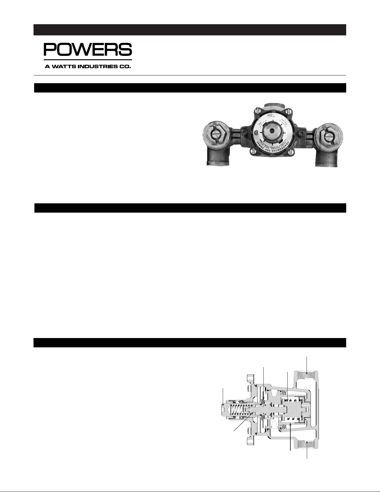
Hydroguard Series e420 Under-the-Counter thermostatic tempering valves are designed for all applications where the temperature of generated hot water must be controlled for safe,
economic use. A powerful advanced thermal actuator quickly
senses and compensates for temperature fluctuations induced
by water temperature and pressure changes in the supply line.
Rugged construction features cast brass body and corrosionresistant internal components for years of dependable, troublefree service. Stem makes temperature adjustment quick and
easy. Hex in with an allen wrench
For restricted access control, the Series e420 UTC valve can be
housed in a stainless-steel or white baked enamel steel cabinet
and can be packaged with solenoid valve(s) (for ESP electronic
faucets), checkstops or other accessories common to Powers’
cabinet supply offering (required to prevent crossflow).
TECHNICAL INSTRUCTIONS
Hydroguard T/P Series e420
Under-the-Counter Thermostatic Tempering Valve
DESCRIPTION
SPECIFICATIONS
Valve Construction:
Under-the-Counter thermostatic mixing valve, with heavy cast bronze body and brass stem with allen wrench adjustment
Connections . . . . . . . . . . . . . . . . . . . . . . . . . . . . . . . . . . . . . . . . . . . . . . . . . . . . . . . . . . . . . .1/2” NPT Inlets and 1/2” NPT Top Outlet
Capacity . . . . . . . . . . . . . . . . . . . . . . . . . . . . . . . . . . . . . . . . . . . . . . . . . . . . . . . . . . . .5.25 gpm [19.8 L/min]* (±0.25 gpm [0.94 L/min])
Maximum Hot Water Supply Temperature . . . . . . . . . . . . . . . . . . . . . . . . . . . . . . . . . . . . . . . . . . . . . . . . . . . . . . . . .190°F [88°C]
Minimum Hot Water Supply Temperature (not applicable to low temperature hot water valve) . . . .5°F [2.8°C] above set point
Maximum Operating Pressure . . . . . . . . . . . . . . . . . . . . . . . . . . . . . . . . . . . . . . . . . . . . . . . . . . . . . . . . . . . . . .125 psig [862 kPa]
Temperature Range . . . . . . . . . . . . . . . . . . . . . . . . . . . . . . . . . . . . . . . . . . . . . . 90°-110°F Type P/65°–115°F [18°–46°C] Type T
Maximum Static Pressure . . . . . . . . . . . . . . . . . . . . . . . . . . . . . . . . . . . . . . . . . . . . . . . . . . . . . . . . . . . . . . . . .125 psig [862 kPa]
Minimum Flow . . . . . . . . . . . . . . . . . . . . . . . . . . . . . . . . . . . . . . . . . . . . . . . . . . . . . . . . . . . . . . . . . . . . . . . . . .1.0 gpm [3.8 L/min]
Shipping Weight . . . . . . . . . . . . . . . . . . . . . . . . . . . . . . . . . . . . . . . . . . . . . . . . . . . . . . . . . . . . . . . . . . . . . . . . . . . . .5 lbs. [2.3 kg]
The Hydroguard Series e420 Under-the-Counter valves meet the above operating conditions as stated in ASSE 1016 T/P (45 psi pressure
differential, hot water supply between 140°–180°F [60°–82°C], cold water supply less than 70°F [21°C]).
If your operating conditions vary from those stated in the standard, performance may vary as well. Consult your local sales representative or
a Powers factory engineer to discuss your specific application. All Powers Under-the-Counter thermostatic mixing valves perform to the
requirements of standards ASSE 1016 and CSA B125.
* At 45 psi differential [310 kPa], with hot water supply between 140°–180°F [60–82°C] and 50/50 mix.
Shown above: Model e420-RB-E-S-S-O-O
OPERATION
Hot and cold water enter respective ports in the valve and mix
in a chamber containing an advanced thermal actuator (refer
to cutaway view). This actuator controls the valve assembly.
Rotating the adjustment handle repositions the shuttle in the
cartridge assembly to produce the desired temperature. If the
hot or cold supply water temperature or pressure changes, the
thermal actuator will contract or expand. This movement repositions the shuttle to maintain the desired temperature.
The standard Hydroguard e420 UTC valve is factory set to
deliver tempered water of 110°F [43°C] with equal supply
pressures, with hot water temperature 14O°F [60°C], cold
water temperature 6O°F [15.6°C].
Shutoff Disc
Shuttle
Hot Water Supply
Cold Water Supply
Cartridge
Advanced
Thermal
Actuator
Adjustment
Stem
Form TIE420U
Page 2
TIE420U Page 2
SAFETY AND PERFORMANCE GUIDELINES
Adherence to these guidelines and recommendations promotes
safe product use and ensures proper valve performance.
1. Thermostatic water mixing valves are control devices which
must be cleaned and maintained on a regular basis. Powers
specifies periodic maintenance at least once a year or immediately after any changes are made to the plumbing system.
Although annual cleaning is recommended, frequency of cleaning depends on quality of local water conditions. Refer to
Preventive Maintenance below for recommended cleaning procedure.
2. Quick closing valves may cause damage to the mixing valve by
creating shock waves. When the e420 Hydroguard supplies
tempered water to self-closing and/or solenoid valves, Powers
recommends use of a shock absorber (Powers Part No. 460-
353) on the discharge line. This protects the e420 Hydroguard
valve from damage.
3. Locate the valve as close as possible to outlet fixture to avoid
waste of energy and water except in applications where the
valve is used as a primary mixing valve to supply an entire building.
4. Correct valve sizing affects valve and system performance;
under or over-sizing of the mixing valve(s) can cause poor operation and possibly injury.
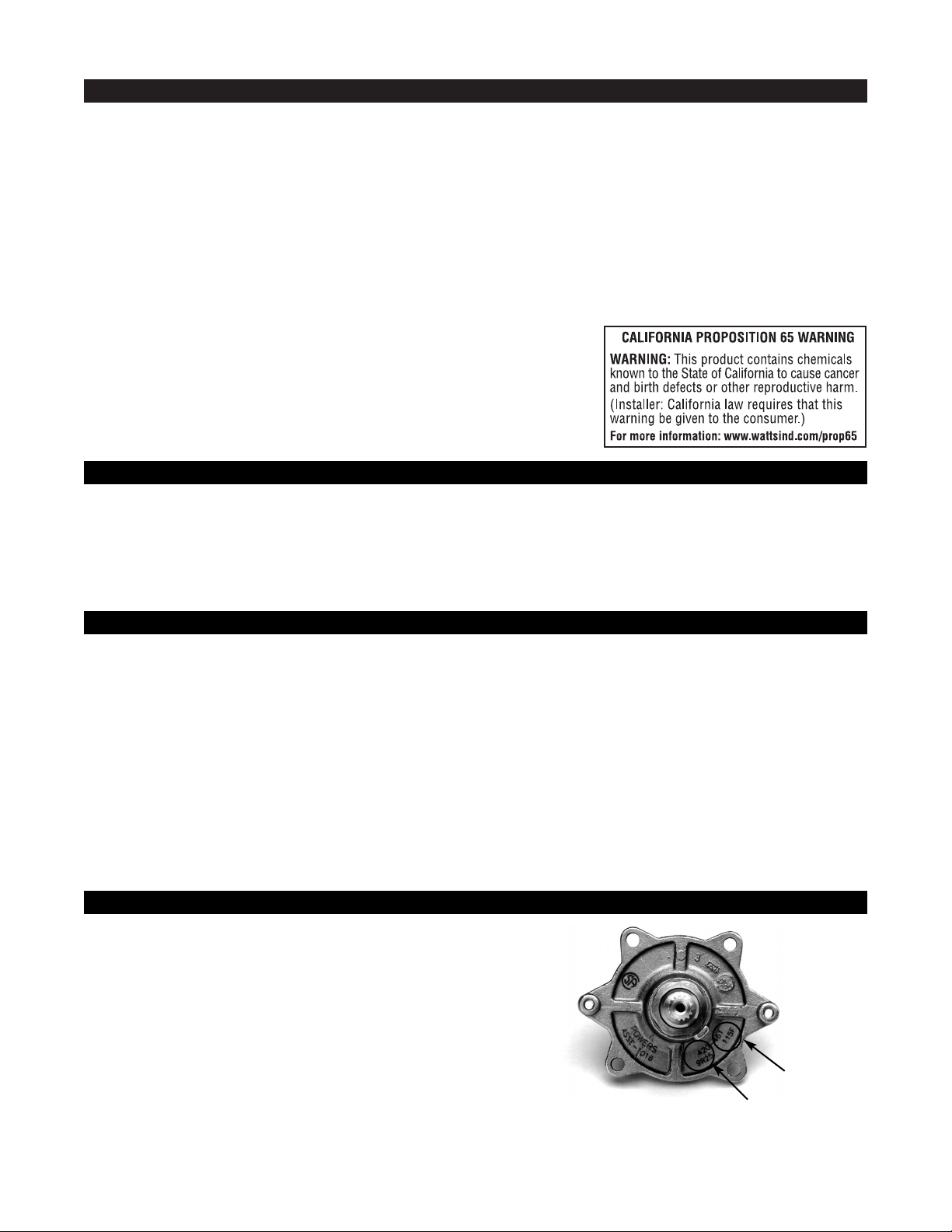
To be sure you are installing appropriate parts into your valve,
determine the model number. The easiest way to do that is to
look at the date code (found on the bonnet of the valve). The
date code (not to be confused with the product or part number) is a four-digit code. Its purpose is to record the
model/version number of the product itself and the date of
manufacture. (See circle "B" in the figure below for location of
date code.)
In the example below, the Date Code is labeled by circle "B".
The first digit, 8, indicates the model number. The bonnet also
indicates the maximum setting. In the figure below, circle "A"
shows the location of the temperature range: "115" (a standard valve).
Checkstops are required with this valve to prevent crossflow.
PREVENTIVE MAINTENANCE
TROUBLESHOOTING
MODEL IDENTIFICATION
Every Six Months: Check and adjust the temperature setting
(see instructions below).
Every Twelve Months:
1. Shut off water supply.
2. Open up checkstops (if any).
3. Clean strainers (if any) and check for free movement of
checkstop poppet.
4. Remove the bonnet and check for freedom of movement
of internal components.
5. Replace seals if cracked, cut, or worn.
6. Reassemble.
7. Adjust stem to desired temperature.
1. The flow of water is less than desired…
• valves upstream from supply not fully open
•low supply pressures
• accumulation of lime deposits in hot water pipes, restricting
the flow of hot water
• checkstops not fully open
• clogged strainer screens in the checkstops
• clogged cartridge
2. Flow of water is completely shut off…
• valves upstream from supply completely closed
•failure of cold water supply pressure (the e420 Hydroguard
is designed to shut off on a cold water supply failure)
• checkstops completely closed
3. Flow is untempered hot or cold water…
• accumulation of lime deposits in hot water pipes, restricting
the flow of hot water
• thermostatic actuator failure; replace with new thermostatic
actuator
• hot and cold water supplies are connected to the wrong
ports
4. Maximum temperature specified for the e420 Hydroguard cannot be obtained…
• accumulation of lime deposits in hot water pipes, -restricting
the flow of hot water
• hot water supply temperature is too low
5. Variable discharge temperature occurs…
• extreme pressure variations in supply lines
• valve operating below minimum capacity requirements
Nameplate Stamp
A
B
Page 3

TIE420U Page 3
PARTS LIST
REPAIR KIT PART NUMBERS
Problem Recommended Kit Type Repair Kit No. Includes Items
Variable or untempered Thermal Actuator 420-453 Thermal Motor, Bonnet O-Ring,
discharge temperature (21, 23)
Water leaks at bonnet/body Soft Parts Kit 420-456 Stem O-Ring, Bonnet O-Ring,
Shutoff Disc
Variable or untempered discharge temperature Cartridge Kit 420-452 Cartridge, O-Rings,
continues after motor replacement
Bonnet Kit 420-610 Bonnet O-Ring
Models 8-9 Upgrade Kit 420-611 All items except 27
227-258
047-129
047-029
420-140
420-024
420-139A
420-210
030-887
225-404
420-508
420-578
16
14
17
18
4
20
21
22
23
25
27
26
24
Item # Product # Description Material
4 420-214 Screw Kit (12 pcs.) Stainless Steel
4A 080-050 Vandal Resistant Screw Kit (12 pcs) Stainless Steel
14 084-014 Stem “O” Ring Buna N
16 420-578 Packing Gland Brass
17 225-404 Huva Cup Buna N
18 420-210 Packing Stop Ring Brass
20 * Bonnet (use 420-610 kit)
21 047-128 Bonnet “O” Ring
22 * Stem (use 420-610 bonnet kit) Brass
23 * Thermal Actuator (use 420-453 kit)
24 * Cartridge (use 420-452 kit)
25 * “O” Ring (use 420-610 bonnet kit) Buna N
26 * “O” Ring (use 420-610 bonnet kit) Buna N
27 N/A Body Brass
N/A = item not available as an individual commercial part.
Page 4

DIMENSIONAL DATA
CHECKSTOPS
© February 2001 Powers, a Watts Industries Co.
3400 Oakton Street, Skokie, IL 60076 Phone: 800.669.5430 • 847.673.6700 • Fax: 847.673.9044
www.powerscontrols.com
5435 North Service Road, Burlington, Ontario, L7L 5H7 Canada • Phone: 888.208.8927 • Fax: 888.882.1979
WARRANTY INFORMATION
Powers warrants that the equipment manufactured by it is free from defects in material and workmanship and, without charge, equipment
found to be defective in material and workmanship will be repaired, or at Seller’s option, replaced F.O.B. original point of shipment, if written notice of failure is received by Seller within one (2) years after date of shipment, provided said equipment has been properly installed,
operated in accordance with Seller’s instructions, and provided such defects are not due to abuse or chemical decomposition by chemical
or galvanic action. This express warranty is in lieu of and excludes all other warranties, guarantees, or representations, express or implied.
There are no implied warranties of merchantability or of fitness for a particular purpose. The Seller assumes no responsibility for repairs
made on Seller’s equipment unless done by Seller’s authorized personnel, or by written authority from the Seller. The Seller makes no guarantee with respect to material not manufactured by it.
SERVICING
1. Remove four bonnet screws (16) and pull out bonnet assembly. The motor should come out with the bonnet. If not, it
can easily be pulled out.
2. Remove the cartridge with tool (supplied) and a screwdriver
or pliers.
Before disassembling valve piping, turn off valve and the
supply water upstream.
TIE420U Page 4
3. Reassemble the valve in reverse order.
4.IMPORTANT: After completing any maintenance/repairs,
check maximum discharge temperature. Adjust if necessary.
Form TIE420U 0218 EDP# 6508935 Printed in U.S.A.
 Loading...