

Page 1
Series e420 Combination Tempering Valve Model 1
Technical Instructions
Description
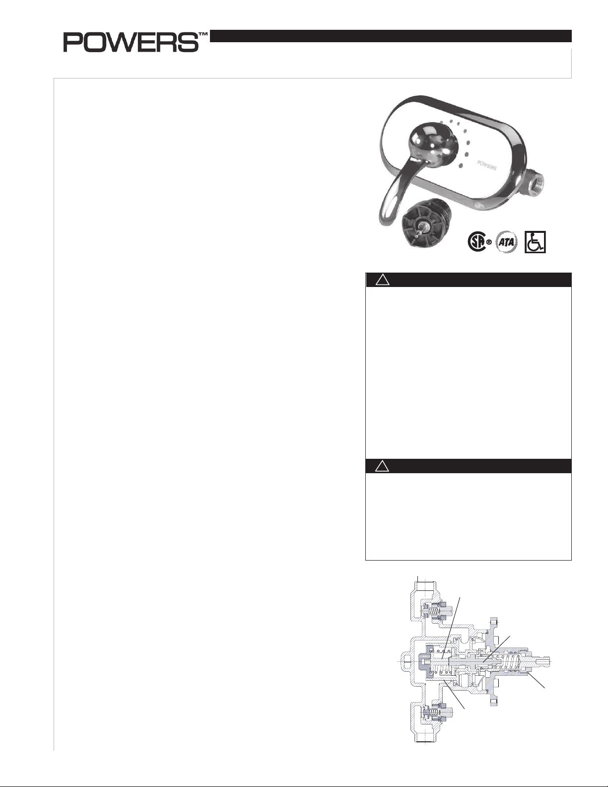
The Series e420 HydroGuard® T/P automatically mixes hot and cold water to
deliver blended water within a specified range. Using an advanced thermal actuator, the Series e420 quickly compensates for temperature fluctuations induced by
water temperature and pressure changes. In the event of cold water failure, the
thermostatic motor virtually shuts of the flow of hot water.
Featuring heavy, cast-brass construction and integral checkstops, all parts of
the e420 Series valve are accessible from the front of the valve and are corrosion resistant. The unit also features a metal to metal temperature limit stop, and
all Series e420 valves open in the cold water position to ensure maximum bather
safety and comfort.
The accuracy, reliability and water economy of the Series e420 HydroGuard
make it preferable for applications that require precise, consistent water control:
showers, baths, hospital hydrotherapy and residential areas.
Many HydroGuard
the Americans with Disabilities Act (ADA).
Specifications n
Valve Construction: Thermostatic mixing valve, with heavy cast bronze
body, metal to metal temperature limit stop, integral checkstops and brass stem.
Available with ADA-compliant lever handle.
Connections: ..................................................................... 1/2" NPT inlets/outlets
1/2" sweat inlets/outlets
Capacity ............................................................................. 5.0 gpm [19.0 L/min]
(±0.25 gpm [0.90 L/min])
Checkstops ....................................................................... Integral to casting
Maximum Hot Water Supply Temperature ................. 190°F (88°C)
Minimum Hot Water Supply Temperature .................. 10°F (6°C) above set point
Maximum Operating Pressure ...................................... 125 psig (862 kPa)
Temperature Ranges
ASSE 1016 Type T/P ........................................................ 90 - 110°F (32 - 43°C)
ASSE 1016 Type T ............................................................ 65 - 115°F (18 - 46°C)
Temperature Limit Stop . ................................................. Adjustable (factory set at
110°F [43°C])
Maximum Static Pressure .............................................. 125 psig (862 kPa)
Minimum Flow: ................................................................. 1 gpm (3.781 L/min)
Certification ...................................................................... CSA B125
Compliance ....................................................................... ASSE 1016 Type T/P
Shipping Weight ............................................................... 5 lbs. (2.3 kg)
All HydroGuard
specifications based on typical operating conditions as stated in ASSE 1016 [45 psi
pressure differential, hot water supply between 140°-180°F (60°-82°C), cold water
supply less than 70°F (21°C)].
If your operating conditions vary from those stated in the standard, performance
may vary as well. Consult your local sales representative or the Powers technical
support department @ 1.800.669.5430, Press "2" to discuss your specific application.
All Powers thermostatic mixing valves perform to the requirements of standards
ASSE 1016 Type T/P and CSA B125.
n
®
®
Series e420 valves and shower systems can be selected to meet
*
®
Series e420 thermostatic mixing valves meet above performance
IS-P-e420
HydroGuard® T/P
Advanced Thermal Activation
!
W A R N I N G
FAILURE TO COMPLY WITH PROPER INSTALLATION
AND MAINTENANCE INSTRUCTIONS COULD
CONTRIBUTE TO THE VALVE FAILURE, RESULTING
IN INJURY AND/OR DEATH.
TO ENSURE THE ACCURATE AND RELIABLE OPERATION OF THIS PRODUCT, IT IS ESSENTIAL TO:
• Properly design the system to minimize pressure and
temperature variations.
• Conduct an annual maintenance program to ensure
proper operation of all critical components.
• Check outlet temperature to ensure it does not
exceed 110°F (43°C). Make sure temperature limit
stop is properly re-set to maximum 110°F (43°C) following valve maintenance or repair. Tampering with
limit stop in any way may result in scalding temperature causing serious bodily harm and/or death.
!
W A R N I N G
Need for Periodic Inspection: Periodic inspection by a
licensed contractor is recommended. Corrosive water
conditions, and/or unauthorized adjustments or repair
could render the valve ineffective for service intended.
Regular checking and cleaning of the valve’s internal
components and check stops helps assure maximum
life and proper product function. Frequency of cleaning
and inspection depends upon local water conditions.
Cold Water Supply
Shuttle
Advance Thermal
Actuator
Operation n
Hot and cold water enter respective ports in the valve and mix in a chamber containing an advanced thermal actuator (refer to cutaway view). This actuator senses
and maintains the set point of the valve.
Rotating the adjustment handle repositions the shuttle in the cartridge assembly
to produce the desired temperature. The mixed water passes over the shutoff disc
* At 45 psi differential [310 kPa], with hot water supply between 140°–180°F [60–82°C].
Temperature
Limiting Stop
Cartridge
Assembly
Hot Water Supply
Page 2
Operation cont. n
to the outlet. If the hot or cold supply water temperature or pressure
changes, the thermal actuator will contract or expand. This movement
repositions the shuttle to maintain the desired temperature. With the
adjustment handle in full clockwise (OFF) position, the shutoff disc
closes the mixing chamber from the outlet.
Installation n
A temperature limit stop limits the movement of the control handle. The
standard HydroGuard
®
e420 valve is factory set to deliver tempered
water up to 110°F [43°C] with equal supply pressures, with hot water
temperature 140°F [60°C], cold water temperature 60°F [15.6°C]
NOTE: Installation should be in accordance with accepted plumbing
practices. Flush all piping thoroughly before installation. Failure to do
so can result in a valve malfunction.
TO INSTALL
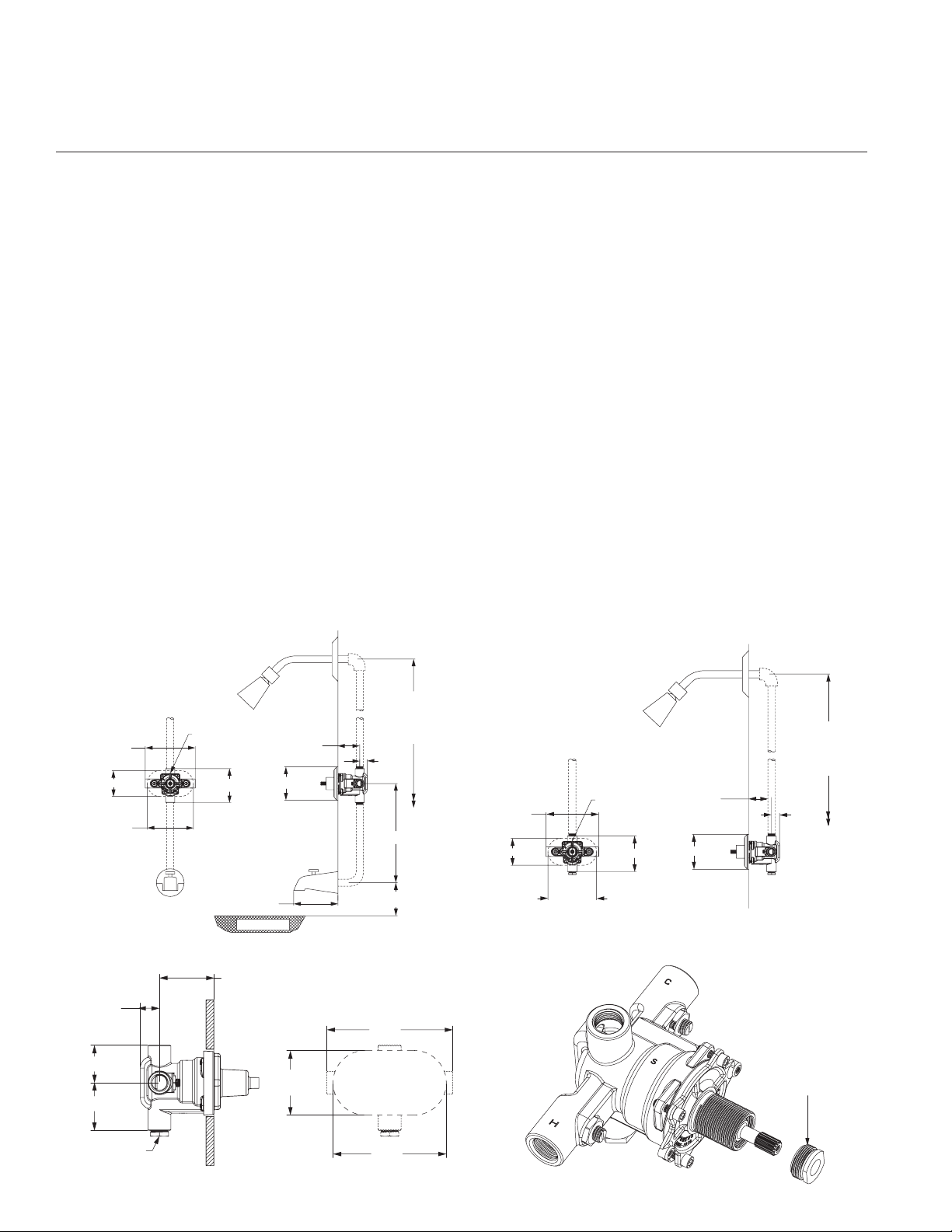
1 . Position mixing valve 2 3/4" ±3/8" (69mm ± 10mm) from inlet center
to finished wall surface. For reference a rough-in guide is provided,
ensure it is pushed on fully and the valve is closed when positioning
valve. The tub outlet port is marked TUB” and should face down.
Facing the front of the mixing valve, connect hot water to left side
and connect cold water to right side. The mixing valve has “C” and
“H” cast into the body near the appropriate ports. Inlets and outlet
connections must be piped correctly for proper operation of valve.
If hot and cold water connections are reversed, valve will not function properly.
2. For tub and shower installations, see Figure 1. Pipe bottom outlet
port “TUB” directly to the diverter tub spout. The mixing valve is
designed to operate without the use of a twin ell. Pipe top outlet port
“S” to the showerhead.
3. For shower only installation, see Figure 2. Pipe top outlet port “S”
directly to the showerhead and plug bottom port.
CAUTION: When soldering during the installation process, do not
heat the valve any higher than the temperature required to flow solder.
Excessive overheating of the valve may cause damage to the valve
internals. By following this recommendation, you will be able to solder
the valve without removing either the cartridge or the checkstops internals. If either brazing or resistance (electric) solder is used, all checkstop and valve internals must be removed.
Wall
Figure 1:
Rough-in Dimensions
– Tub and Shower
6 1/16"
(155mm)
3 1/8"(79mm)
5 1/2"
(139mm)
All Dotted Line Piping
Supplied By Others
"S" to Be
on Top
4 1/8"(105mm)
5 3/8"(137mm)
3 1/8"(79mm) max
2 3/8"(60mm) min
4"(101mm)
Tub Rim
78" (1981mm)
Approx.
To Finished
Floor
15/16"
(23mm)
12" (305mm)
4" (102mm) Approx
Figure 3:
Rough-in Guide
15/16"
(23mm)
1 13/16"(46mm)
2 5/16"(58mm)
3 1/8"(79mm) max
2 3/8"(60mm) min
6 1/16"
(155mm)
3 1/8"
(79mm)
4. Turn hot and cold water supplies on and verify there are no leaks.
5. Rough-in guide installation
a. Before strapping the pipes and before completing the finished
wall, slide rough-in guide onto the mixing valve stem and press
fit into place, see Figure 3. (valve stem must be rotated fully
clockwise).
b. The rough-in guide will insure the proper size opening and
location of the finish wall.
6. After finished wall is completed, remove rough-in guide to allow
installation of the trim.
7 . Peel off backing of dial gasket and attached it to the inside top edge
of dial plate. Make sure gasket is approximately 1/16" beyond the
plate edge.
8. Hold plate firmly against the wall. Thread sleeve on the bonnet making sure that the cut away on the sleeve is towards you and is in
the bottom position when tightened. Do not use any tool to tighten
which will scratch the sleeve surface.
9. Install handle with the screw provided.
10. Maximum temperature setting adjustment (Figure 4) must be set on
the job. The high temperature limit stop is threaded into the bonnet
and is turned counter clockwise for an increased setting and clockwise for a decreased setting. Powers recommends a maximum
setting of 110°F (43°C). To adjust temperature, rotate handle to the
maximum desired outlet temperature, screw temperature limit stop
until it touches stem’s shoulder. Close valve and open it to verify
setting.
WALL
Figure 2:
WALL
Rough-in Dimensions
– Shower Only
ALL DOTTED LINE
PIPING SUPPLIED
BY OTHERS.
6 1/16"
6 1/8" [155]
(155mm)
3 1/8" [79]
3 1/8"(79mm)
R1 5/8" [R40]
All Dotted Line Piping
Supplied By Others
"S" to Be
'S' TO BE
on Top
ON TOP
4 1/8"(105mm)
5 1/2"
5 5/8" [142]
(139mm)
4 1/8" [105]
1/2" NPTF
CONNECTIONS
1/2" NPT
MALE INLET
1 7/16" [37] MIN.
3 1/8"(79) max
2 7/16" [62] MAX.
2 3/8"(60) min
Ø4" [102]
4"(101mm)
78" (1981mm)
78" [1981]
Approx.
APPROX.
TO FINISHED
To Finished
FLOOR
Floor
15/16"
7/8" [23]
(23mm)
Figure 4:
Max Temperature
Setting
Clockwise for
cooler temperature.
Counter clockwise
for warmer temperature
Optional For
3 Port Valve
SIDE VIEW
5 1/2"
(139mm)
FRONT VIEW
2
Page 3

Preventative Maintenance n
NOTE: Before servicing checkstops or piping, always turn off the
upstream water supply.
EVERY 12 MONTHS:
Open up the checkstops and check for free movement of the poppet.
To access the checkstops, remove the valve handle assembly and dial
plate.
Before servicing, turn off the water supply upstream.
To close the checkstops, turn the adjustment screw fully clockwise on
each checkstop.
Remove the valve bonnet and rinse all grit and impurities from the
internal components.
Winterize valves that are used outdoors. Remove and store the internal
components and drain all water from the valve.
Safety Guidelines - All Models n
Adherence to these guidelines and recommendations promotes safe
product use and ensures proper valve performance.
1. Thermostatic water mixing valves are control devices which must be
cleaned and maintained on a regular basis. Powers specifies periodic maintenance at least once a year or immediately after any changes are made to the plumbing system. Annual cleaning and inspection
is recommended, however, frequency of cleaning depends on quality
of local water conditions. Refer to the Preventive Maintenance section for recommended cleaning procedure.
EVERY 3 MONTHS:
Every three months, check the maximum temperature
setting (handle rotation setting).
W A R N I N G
!
Always verify the maximum temperature setting of the valve
when any changes ar ance/safety program.
3. Quick closing valves may cause damage to the mixing valve by creating shock waves. When the HydroGuard
®
supplies tempered water
to self-closing and/or solenoid valves, Powers recommends installing a shock absorber (Powers Part #460-353) on the discharge line,
which will protect the HydroGuard
®
from damage.
4. Position the e420 valve as close as possible to outlet fixture to avoid
waste of energy and water (except in applications where the valve is
used as a primary mixing valve).
2. WARNING: To prevent injury to the user, it is important to periodi-
cally check the maximum temperature adjustment on the valve.
Servicing n
To Disassemble:
1. Turn off hot & cold water supply-stops
2. Remove the handle and trim plate
3. Remove 4 bonnet screws and bonnet assembly
4. Remove all internal components from valve body
5. At this point you should have an empty valve body.
WARNING: After completing any maintenance/repairs, reset the high
temperature limit stop.
To Reassemble:
1. Ensure the inside of the valve body is free of deposits and debris.
Clean as necessary.
2. Push the cartridge into the body without the “O” rings installed. The
cartridge should slide in easily, and bottom out with its large fins just
inside the front surface of the casting. If the cartridge is difficult to
install, or does not go in all the way, remove the cartridge and clean
the body or remove any obstructions. Repeat this step until the cartridge installs easily.
3. Remove the cartridge and install the 2 “O” rings. Lubricate the “O”
rings with silicon lubricant.
4. Install the cartridge back into the body. The cartridge should go in
until the large fins are just inside the front surface of the casting
(same position as in step 2).If you cannot push it in all the way due to
O-rings, use bonnet and two (2) screws to force in.
5. Place the wax element into the stem assembly, stem
side first, and place this bonnet-stem-motor assembly
into/onto the valve body. Rotate the bonnet assembly to line up the
bonnet screw holes and reinstall and tighten
the four bonnet screws.
6. With handle, rotate the stem assembly clockwise, until
it bottoms out on the cartridge. At this point your valve is in the off
position.
7. Turn the hot and cold water supplies back on and verify
there is no leakage.
8. Verify proper operation by rotating the stem from the
off position, counterclockwise, to the high temperature position.
Verify the temperature does not exceed your desired maximum temperature. Rotate stem back to the
off position.
9. Leave the adjusting stem in the full hot position
to determine the high temperature limit stop is set
properly. If not, rotate clockwise or counterclockwise, decrease or
increase the high temperature limit stop respectively. Powers recommends a maximum setting
of 110°F (43°C).
10. Install handle with the screw provided onto the stem and tighten in
place. Ensure that the set screw lines up with the groove on the
adjustment stem.
3
Page 4

Troubleshooting n
What to look for if:
The maximum temperature cannot be obtained...
a. Lime deposits may have accumulated in the hot water pipes, restrict-
ing the hot water supply.
b. The hot water supply temperature may be too low.
c. The temperature limit stop setting may be too low. Remove valve
handle, and readjust the temperature limit stop.
Flow of water is less than desired…
a. The upstream supply valves may not be fully open.
b. The inlet supply pressure(s) may be low.
c. Lime deposits may have accumulated in cartridge, restricting water
flow.
d. The showerhead may be clogged. Remove and clean.
e. The checkstops may be clogged. Clean check stops.
Parts List - E420 Model 1 n
The valve opens with hot water flow rather than cold water flow...
a. The inlet water supplies are connected to the wrong ports. Remove
the valve and reinstall.
Flow of water is completely shut off...
a. The upstream supply valves may be completely closed.
b. The hot or cold water supply pressure may have failed. The
HydroGuard
®
420 valve is designed to reduce the flow of water upon
either supply failure.
c. The checkstops may be closed. Access the checkstops and open by
turning the adjustment screw fully counterclockwise.
Index Part # Description
1 N/A Body Machined
2 200 046 1/2" Plug, Threaded
3 900 050 Kit, Check Stop
4 420 452 Kit, Cartridge
5 420 453 Wax Element Kit
6 420 457 Kit, Bonnet
7 420 046 Kit, Trim Plate, Color Coded
8 420 047 Kit, Trim Plate, Etched
9 420 049 Handle Kit, Dome
10 473 024
1/2" Plug, Sweat
ATTENTION INSTALLER: After installation, please leave this
Instruction Sheet for occupant’s information.
IMPORTANT: Inquire with governing authorities for local
installation requirements.
Warranty n
The Seller warrants that the equipment manufactured by it and covered by this order or contract is free from defects in material and workmanship and, without
charge, equipment found to be defective in material or workmanship will be repaired, or at Seller’s option replaced F.O.B. original point of shipment, if written
notice of failure is received by Seller within one (1) year after date of shipment (unless specifically noted elsewhere), provided said equipment has been properly
installed, operated in accordance with the Seller’s instructions, and provided such defects are not due to abuse or decomposition by chemical or galvanic action.
THIS EXPRESS WARRANTY IS IN LIEU OF AND EXCLUDES ALL OTHER WARRANTIES, GUARANTEES, OR REPRESENTATIONS, EXPRESS OF IMPLIED. THERE ARE
NO IMPLIED WARRANTIES OF MERCHANTABILITY OR OF FITNESS FOR A PARTICULAR PURPOSE. The Seller assumes no responsibility for repairs made on the
Seller’s equipment unless done by the Seller’s authorized personnel, or by written authority from the Seller. The Seller makes no guarantee with respect to material
not manufactured by it.
A Watts Water Technologies Company
IS-P-e420 1045 EDP# 6511214 © 2010 Powers
USA: Phone: 1.800.669.5430 • Fax 1.847. 229.0526 • www.powerscontrols.com
Canada: Phone: 1.888.208.8927 • Fax 1.888. 479. 2887 • www.powerscontrols.ca
 Loading...