

Page 1

Technical Instructions
Features
• Low cost
• Built-in volume booster
• Small size
• Field reversible
• Low air consumption
• Mounts at any angle
• Convenient external Span and Zero adjusts
• Light Weight
• Wide supply pressure range
• Low supply pressure sensitivity
Operating Characteristics n
Supply Pressure Range: ........................................ Min: 3 psig (21 kPa) above
max output
Max: 100 psig (700 kPa)
Supply Pressure Sensitivity: ................................. <±0.15% of span per 10 kPa
at midrange
(<±0.1% of span per psig)
Terminal Based Linearity: ..................................... <±1.0% of span
Repeatability: ........................................................... <0.5% of span
Hysteresis: ............................................................... <1.0% of span
Air consumption (Maximum): ............................... 0.1 SCFM (0.2m3/hr)
at midrange
Flow Rate at Midrange (Minimum): ..................... 4.5 SCFM (7.6m3/hr ANR) at
25 psig (175 kPa) supply;
12 SCFM (20.0 m3/hr ANR) at
100 psig (700 kPa) supply
Port Sizes: ................................................................ 1/4 NPT (pneumatic);
1/2 NPT (electric)
Size: ........................................................................... 2-1/8 in. x 2-1/8 in. x 4 in.
(54 mm x 54 mm x 102 mm)
Weight: ..................................................................... 2.1 lb (0.94 kg)
Impedance (nominal):
512-117 ... 180
512-015 ... 180
512-027 ... 220
Description n
This transducer is an electropneumatic device that reduces a supply
pressure to a regulated output pressure that is directly proportional to an
electrical input signal. It uses a supply pressure between 18 and 100 psig
(125-700 kPa). An integral pneumatic volume booster is included in the
design to provide high flow capacity (up to 12 SCFM).
Three versions of the compact transducers are available. Listed below
are their model numbers, the current input accepted by each, and output
signal emitted by each.
• 512-117...4-20 mA Input/1-17 psi Output
• 512-015...4-20 mA Input/3-15 psi Output
• 512-027...4-20 mA Input/3-27 psi Output
n
IS-P-IP
IP Transducers
Series 512
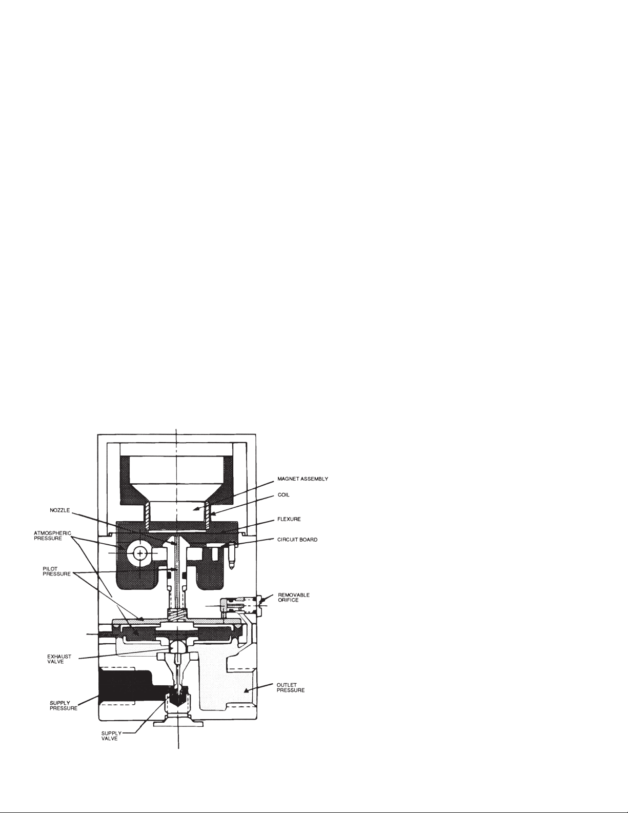
Operating Principle n
The I/P transducer is a force balance device
in which a coil (see figure 1 on page 2) is
suspended in the field of a magnet by a flexure. Current flowing through the coil generates axial movement of the coil and flexure.
The flexure moves against the end of a
nozzle and creates a back pressure in the
nozzle by restricting air flow through it. This
back pressure acts as a pilot pressure to
an integral booster replay. Consequently, as
the input signal increases (or decreases, for
reverse acting), output pressure increases
proportionally. Zero and span are calibrated
by turning easily accessible adjusting
screws on the front face of the unit. The zero
adjusting screw causes the nozzle to move
relative to the flexure. The span adjusting
screw is a potentiometer that limits the current through the coil. A thermistor in series
with the coil provides temperature compensation.
Page 2
Mounting
Installation n
The 512 series transducers can be pipe, panel, or bracket
mounted in any position. Positions other than vertical will require
recalibration of the zero adjustment. For maximum output pressure stability, the transducer should be mounted in a vibrationfree location or such that vibration is isolated to the X and Z axis
shown on the dimensional drawing (see Figure 2 on page 3).
Field Reversible
All transducers are calibrated at the factory for direct acting
operation but may be used in the reverse acting mode by reversing the polarity of the signal leads and recalibrating. When calibrated for reverse acting applications, the transducers provide a
minimum of their full rated output pressure (i.e., 15, 17, or 27 psig)
upon input signal failure.
Mounting
Pipe:
Due to its light weight, the transducer may be supported using its
own plumbing on pipes used for air supply and output.
Panel (with access to rear of panel):
Attach transducer to panel using two 10-32 screws (supplied)
into the threaded holes on the back of the transducer.
Panel (with no access to rear of panel):
Attach bracket using tow 10-32 screws (supplied) into the
threaded holes on the back of the transducer. Use 10-32 screws
through holes in the bracket to mount transducer to panel.
Flowrite II Valve:
For mounting in the field, use mounting kit (optional accessory,
#512-005), which contains an adapator bracket (AB). First, attach
this AB to the yoke, then attach the mounting bracket (shown in
Figure 2-supplied with transducer) to the AB.
Mounting Notes:
1. Transducer may be mounted at any angle. See "Calibration."
2. Effect of external vibration can be kept at a minimum if unit
is mounted so that vibration is restricted to being along the X
and Z axes shown on the Dimensional Drawing, see figure 2.
Figure 1
Air Connections:
Supply
Connect air supply to 1/4 NPT port marked "IN" on base of unit.
Avoid getting pipe compound in air line and transducer.
Supply air must be instrument quality (filtered and dried).
2
Page 3

Output:
Connect output to 1/4 NPT port marked "OUT" on base of unit.
The two unmarked 1/4 NPT ports may be used as alternate output ports or for a gauge to measure output pressure. Unused
ports must be plugged.
Electrical Connections:
Connect electrical signal to leads exiting side of unit through 1/2
NPT conduit fitting. For direct acting (where increasing signal
increases output pressure), connect positive signal to black
lead and negative to white. For reverse acting (increasing signal
decreases output pressure), connect positive signal to white
lead and negative to black.
Calibration n
Transducer should be calibrated after mounting. If transducer is
calibrated in an upright position, then mounted at an angle, readjustment of the "ZERO" is necessary.
1. Remove plastic cap from "ZERO" and "SPAN" adjustment
screw access holes.
2. Set signal to low end of the signal scale. (For reverse acting,
set to high end of the signal scale).
3. Adjust "ZERO" screw until output pressure is set to the low
end of the output scale. Turn counterclockwise to increase
pressure, clockwise to decrease pressure. If output pressure
does not change when screw is turned, turn screw counterclockwise until pressure starts to rise.
4. Set signal to high end of the signal scale. (For reverse acting,
set to low end of the signal scale).
5. Adjust "SPAN" screw until output pressure is set to the high
end of the output scale.
6. Repeat steps 2, 3, 4, and 5 until no further readjustment is
necessary.
7. Replace protective caps.
Maintenance n
If internal clogging occurs due to improper filtering of the supply
air, the orifice can be cleaned without removing the unit from
its mounting or plumbing. Turn off the supply air. Unscrew and
remove the orifice assembly. Clean the orifice through the side
of the orifice assembly using a wire that has a smaller diameter
than 0.015 in. (0.38 mm). Shake out any loose particles inside of
the orifice assembly. Screw orifice assembly back into unit.
Figure 2
3
Page 4

ATTENTION INSTALLER: After installation, please leave this
Instruction Sheet for occupant’s information.
IMPORTANT: Inquire with governing authorities for local
installation requirements.
A Watts Water Technologies Company
USA: Phone: 1.800.669.5430 • Fax 1.847. 229.0526 • www.powerscontrols.com
Canada: Phone: 1.888.208.8927 • Fax 1.888. 479. 2887 • www.powerscontrols.ca
IS-P-IP 1028 EDP# 6512235 © 2010 Powers
 Loading...