

Page 1
1. Attach checkstops to valve body. Screwed checkstops:
teflon tape is recommended to provide seal. Sweat check-
stops: to lessen potential for overheating of rubber sealing
discs during sweating in process, you must leave checkstop in full open position, or remove all internal parts to prevent melting of the rubber sealing discs.
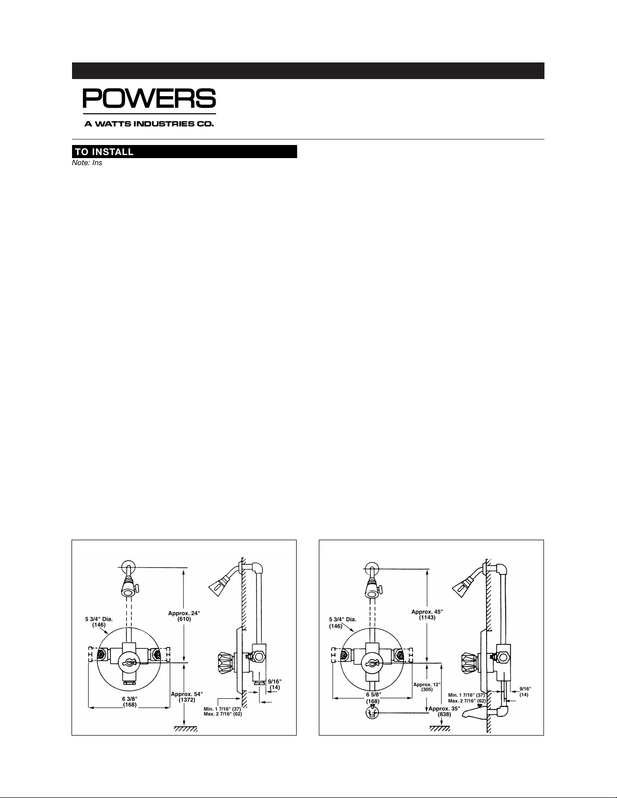
2. Position mixer 2" ± 1/2" (51mm ± 13mm) from inlet center
to finished wall surface. Facing front of mixer, connect hot
water to left side and connect cold water to right side. The
valve has ‘C’ and ‘H’ cast into the body near the appropriate inlet ports.
3. When copper tubing is used, flared fittings are recommended. If flared fittings cannot be used, then the balance cartridge must be removed before soldering near the mixer
body. To remove the balance cartridge: remove the o-ring,
limit stop and sleeve, unscrew bonnet retainer and pull
bonnet out of the mixer body. Pull balance cartridge out
with either pliers or cartridge puller #401-202.
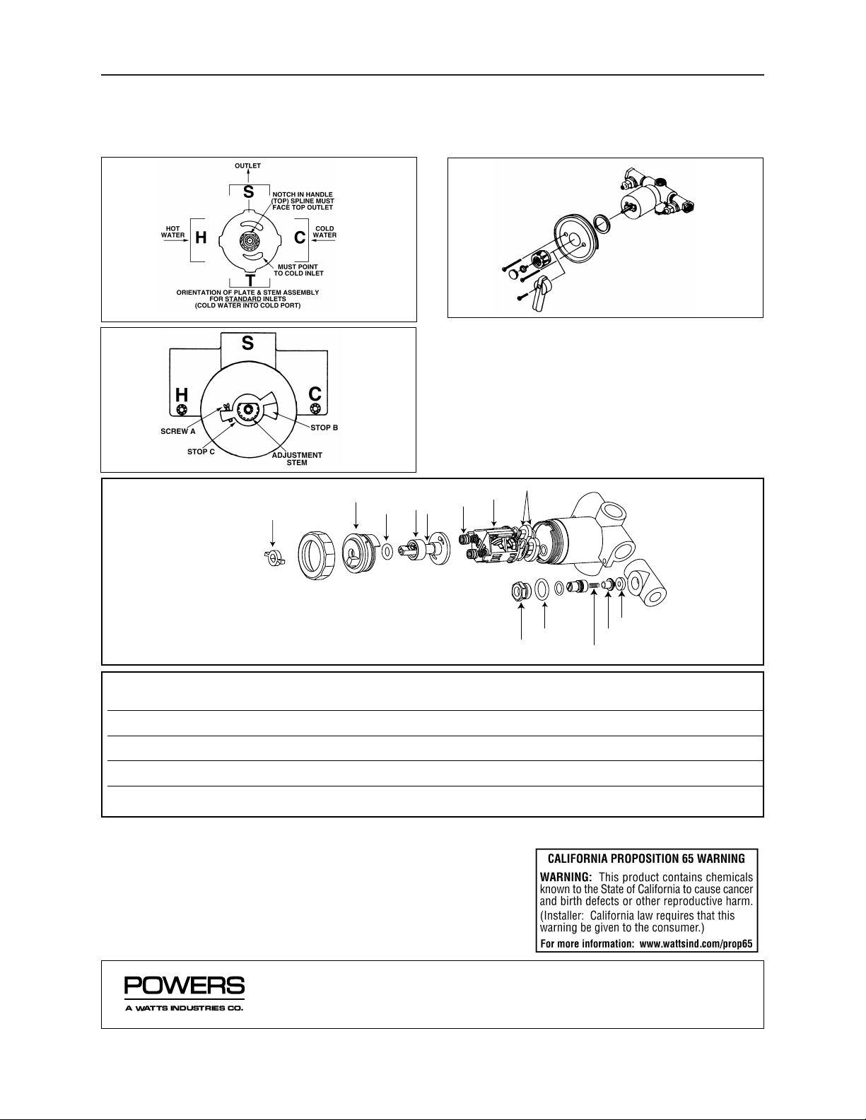
4. Biltmore is factory assembled for top outlet installation, see
Figure 1. For shower only installation, pipe top outlet directly to showerhead and plug bottom port. If reversed inlets
are required, place mixer stem in closed (full clockwise)
position, remove o-ring, limit stop and sleeve, unscrew and
remove bonnet retainer. Pull bonnet, stem and mixing plate
out of mixer body and rotate 180° making certain the alignment tabs on the bonnet are secure in the notches on the
mixer body. Replace bonnet retainer (limit torque to 20 ft.lbs.), slide sleeve over retainer, install limit stop over stem,
replace o-ring. With mixer in closed position, the notch in
the spline on the stem (Figure 3) must face top outlet for
standard inlet installation (cold water to cold port on right
side). For reversed inlets (cold water to hot port on left
side), the notch in the spline on the stem must face bottom
outlet.
Note: hot and cold inlets should be re-identified for
reversed inlets to avoid confusion during future mixer
maintenance.
5. For tub and shower installations, see Figure 2. Pipe bottom
outlet port ‘T’ directly to a diverter tub spout. The Biltmore
is equipped with a built-in diverter fitting in the mixer body,
so it is not necessary to use a twin ell. Pipe top outlet port
‘S’ to the showerhead. For tub installation only, plug top
outlet port ‘S’. Be certain that bottom outlet port ‘T’ is
piped to the tub. If outlet connections are reversed, the
mixer will not function properly.
6. Rough-in procedure: a cardboard sleeve protector is furnished with each Biltmore to protect the chrome plated
sleeve from damage during piping installation. When piping
installation is completed, the installer should remove the
cardboard sleeve protector and slide rough-in guide onto
mixer stem (guide stem is same notched shape as mixer
stem) and snap into place. The rough-in guide will not fit
over the cardboard sleeve protector.
The rough-in guide will insure proper size opening for mixer
and checkstop shut-off and repair accessibility, as well as
protect the chrome plated sleeve from damage during drywall and tile installation.
Position mixer so finished wall surface will be within the 1"
(25mm) dimension on rough-in guide (Figure 6). This
insures the center line of the mixer connections will be
2"±1/2" (51mm ± 13mm) from the finished wall surface.
After wall is completed, remove rough-in guide and attach
dial to mixer body with the screws furnished (Figure 4). To
install dial gasket, peel backing off gasket and attach gasket to inside dial plate.
INSTALLATION INSTRUCTIONS
BILTMORE SERIES 800
Pressure Balancing Valves
Figure 1: Rough-in Dimensions
- inches (millimeters)
A Watts Industries Co.
TO INSTALL
Note: Installation should be in accordance with accepted plumbing
practices. Flush all piping thoroughly before installation. If thin wall
installation is required, refer to Installation Instruction #129-075.
Figure 2: Rough-in Dimensions
- inches (millimeters)
Form II800 v3
Page 2
II800 v3 Page 2
7. MAXIMUM TEMPERATURE SETTING (refer to Figure 5). This
must be set at the jobsite. Mixer will pass full HOT water.
Rotate stem to desired maximum temperature. Adjust screw
A until it touches stop B.
CAUTION: Adjustable stop C must be utilized for proper
operation.
Figure 3
Figure 5
Figure 4
13
1
14
6
7
8
15
3
2
9
10
11
12
TROUBLESHOOTING RECOMMENDED REPAIR KIT
GASKET AND DISC 1) Water leak at stem and/or bonnet 800-030
REPLACEMENT 2) Flow of water continues after mixer is turned off Includes items: 2,3,7(2),9(2),10(2),13(2),15(2)
BALANCING CARTRIDGE 1) Variable or untempered discharge temperature 900-259
Includes items: 2, 3 7(2), 8,15(2)
STEM AND PLATE 1) Flow continues after mixer is turned off 800-032A
REPLACEMENT 2) Handle splines on stem damaged, not grasping Includes items: 1,2,3,6,7(2)
INTERNAL REBUILD KIT Note: Required if both Balancing Cartridge and Stem and Plate 800-163
replacement kits needed Includes items: 2,3,6,7(2),8,15
CHECKSTOP REBUILD KIT 1) Checkstop will not shut-off or allow full flow 900-049
2) Crossover Includes items: 9(2),10(2),11(2),12(2),3(2)
REPAIR KITS: for further
information on repair and
maintenance, see TI800-1.
Form II800v3 0311 EDP# 6512222 Printed in U.S.A.
USA office: Phone: 800.669.5430 • Fax: 847.824.0627
www.powerscontrols.com
Canadian office: Phone: 888.208.8927 • Fax: 888.882.1979
© 2002 Powers, a Watts Industries Co.
A Watts Industries Co.
 Loading...