

Page 1
Technical Instructions
!
WARNING
Read this Manual BEFORE using this equipment.
Failure to read and follow all safety and use information can result in death, serious personal injury,
property damage, or damage to the equipment.
Keep this Manual for future reference.
WARNING
!
FAILURE TO COMPLY WITH PROPER INSTALLATION AND
MAINTENANCE INSTRUCTIONS COULD CONTRIBUTE TO THE
VALVE FAILURE.
This Hot Water Master Tempering Valves cannot be used for
tempering water temperature at fixtures. Severe bodily injury
(i.e., scalding or chilling) and/or death may result depending
upon system water pressure changes and/or supply water
temperature changes. ASSE standard 1016, 1069 or 1070 listed
devices should be used at fixtures to prevent possible injury.
These Hot Water Tempering Valves are designed to be
installed at or near the boiler or water heater. They are not
designed to compensate for system pressure fluctuations and
should not be used where ASSE standard 1016, 1069 or 1070
devices are required. These valves should never be used to
provide “anti-scald” or “anti-chill” service.
The components of the system must be of materials with a
construction capable of withstanding the high limit output temperatures of the water heating source.
AIR OPERATED:
Rigid Stainless Bulb
Direct Action 744-1270
Reverse Action 744-1271
Rigid Copper Bulb
Direct Action 744-1213
Reverse Action 744-1214
Specifications n
IS-P-TC744-1
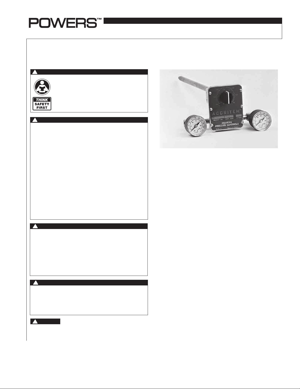
Accritem Controller
Model 3
WATER OPERATED:
Rigid Stainless Bulb
Direct Action 744-1217
Reverse Action 744-1218
!
WARNING
Need for Periodic Inspection and Yearly Maintenance:
Periodic inspection and yearly maintenance by a licensed contractor is required. Corrosive water conditions and/or unauthorized adjustments or repair could render the valve ineffective for
service intended. Regular checking and cleaning of the valve’s
internal components and check stops helps assure maximum
life and proper product function. Frequency of cleaning and
inspection depends upon local water conditions.
!
WARNING
You are required to consult the local building and plumbing
codes prior to installation. If the information in this manual is
not consistent with local building or plumbing codes, the local
codes should be followed. Inquire with governing authorities for
additional local requirements.
!
WARNING
Flush all pipes thoroughly before installation. Installation and
field adjustment are the responsibility of the installer.
Operation .................................... Direct or Reverse Acting
Adjustment Dial Range—Standard 50 to 350°F (10 to 177°C)
Maximum Supply Pressure (air or water)
at Room Temperature
Air Consumption (max.)
Maximum Operating Pressure
Maximum Operating Temperature
Temperature Response
Mounting
....................................................... 1/2" NPT
Air or Water Connections
Drain Connection (water only)
Shipping Weight
.......................................... 4 lbs. (1.8 kg)
Sensitivity (adjustable)
..........................35 psi (241.3 kPa)
......................... 218 cm 3/s (800 SCIM)
...................... 1724 kPa (250 psi)
........................400°F(204°C)
................................... 0.5°F(0.3°C )
..................................... 1/8" NPT
................................ 1/4" NPT
................................3.1 to 27.9 kPa/C
(1/4 to 2-1/4 psi/F)
Maximum Pressure on Wells
Stainless Steel no. 744-082
Copper no. 744-111
Well Dimensions
............................................ See page 6
.................. 1125 psi (7756 kPa)
............................ 525 psi (3619 kPa)
Page 2
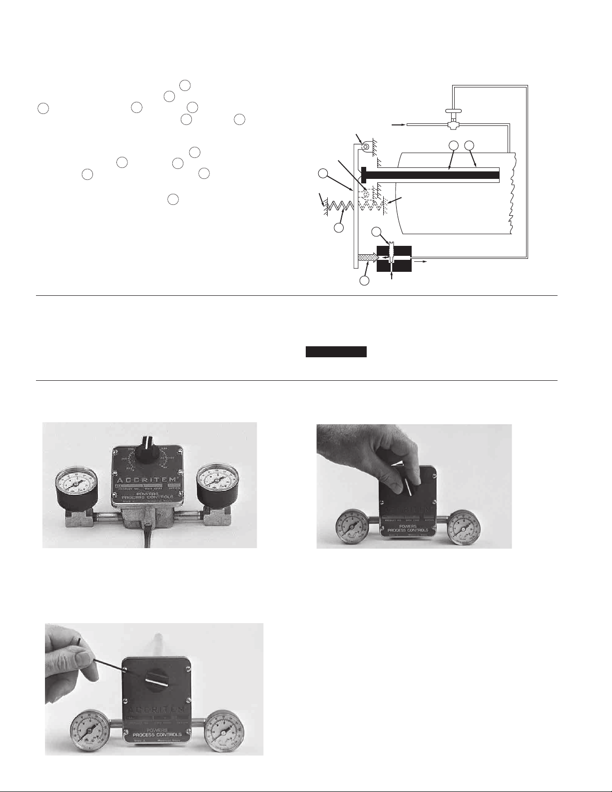
Operation Instructions n
Direct Action Controller
A temperature change in the medium being controlled creates a
change in length of the sensitive tube
ture lengthens the sensitive tube
away from the lever
2
3.
The lever
A, is moved to open the exhaust valve
1
. An increase in tempera-
1
and moves the Invar rod
3
, which pivots at Point
4
by spring
5
. This
permits the supply (air or water) (S) to increase the pressure in the
control line (R) and close the normally-open valve. A decrease in
temperature shortens the sensitive tube
rod against the lever
sure spring
to open the exhaust valve
5,
3.
The lever
3
nd moves the Invar
1 a
moves against the pres-
This exhausts the
4.
pressure in the control line and opens the valve.
The sensitivity adjustment screw
regulates the rate of flow
6
of the supply air (or water) to the controller to a change in temperature. Turning the screw clockwise increases the sensitivity
by reducing the flow and increasing the response time. Turning
the screw counterclockwise decreases the sensitivity by
increasing the flow and reducing the response time.
Also see Figure 8 on page 7.
Sensitivity n
The sensitivity of the Accritem controller is adjusted by turning the restriction screw (Figure 2). (The restriction screw is
factory-set for air operation.) For water operation, the restriction
screw should be opened a minimum of 1/2 turn and controller
recalibrated. Restriction screw must never be fully closed. Make
Figure 1
Positions “B” and “D” (dotted) show
pivot point (“B”) and spring when
controller is REVERSE acting.
Positions “A” and “C” (solid) show pivot
point (“A”) and spring when controller is
DIRECT acting.
3
C
Exhaust Air
A
B
D
5
6
R
4
S
Flowrite Valve
(Normally Open)
2 1
Tank
adjustments slowly, allowing about two (2) minutes after each
adjustment for the controller to balance.
NOTICE
If sensitivity is changed, controller must be recalibrated.
Calibration n
Figure 2
Loosen set screw and turn adjusting knob to indicate
temperature at bulb. Tighten set screw. Set controller for
desired control temperature.
Figure 4
Figure 3
Turn adjusting knob until 52 kPa (7-1/2 psi) control pressure shows on gauge. Read temperature at bulb with
an accurate thermometer.
Set restriction screw for desired sensitivity. Air: 1/8 turn
from closed (minimum). Water: 1/2 turn from closed
(minimum).
2
Page 3
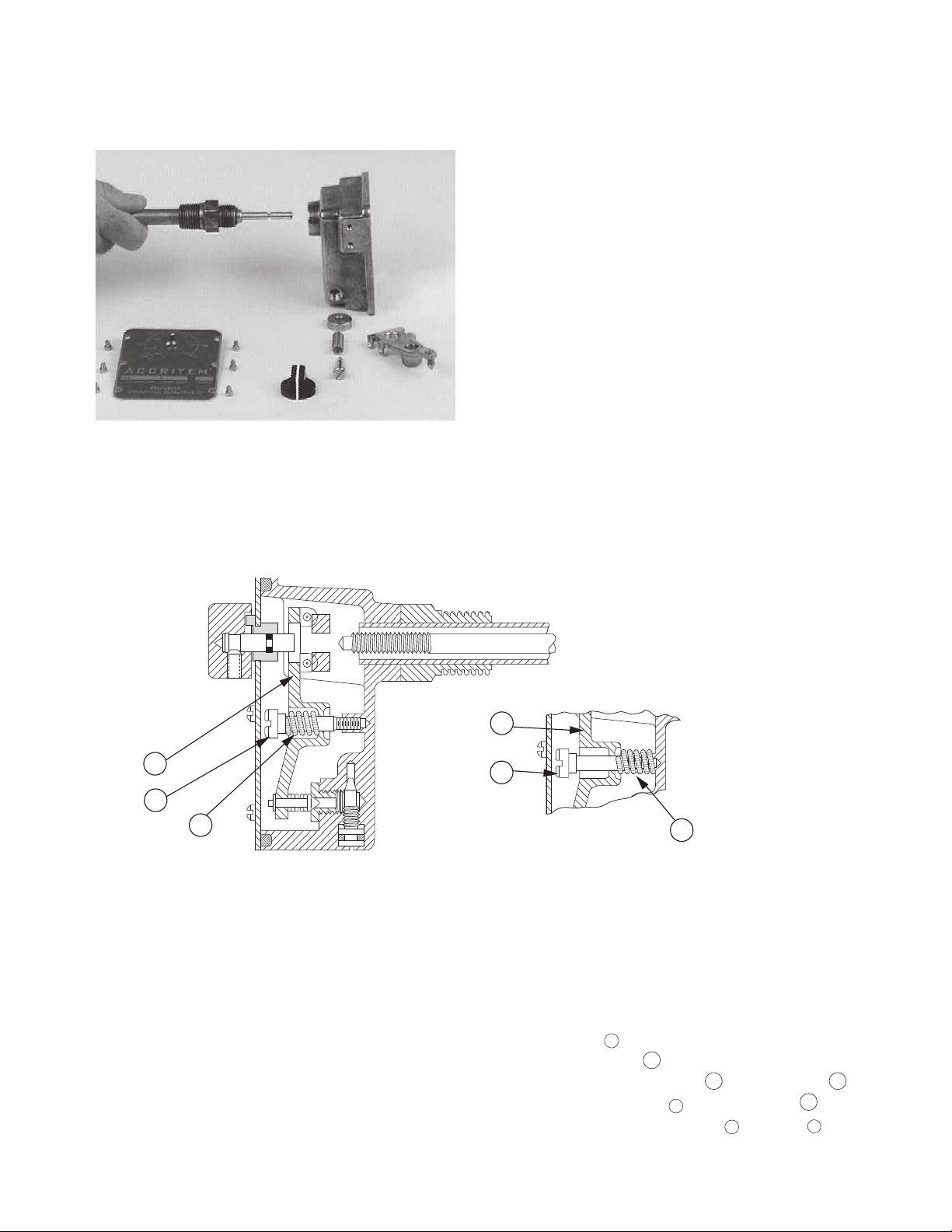
Installation Instructions n
General Instructions
Figure 5.
To disassemble and replace sensitive tube assembly:
The Accritem Controller requires a clean, reliable supply
of compressed air or cold water at room temperature and
15 tgo 20 pounds of pressure. Other fluids may be used,
such as gas, oil, etc., providing provision is made for safe
disposal.
Select sensitive element location with care to insure satisfactory results. Bulb must project entirely into the liquid or air being
controlled.
Flush or blow out all lines before making final connections. Put
supply pressure through all control lines and check for leaks.
INSTALLATION FOR AIR OPERATION
Controller should normally be installed in horizontal position;
however, other positions may be used if the supply and control
connections are parallel with the ground and calibration is
checked after installation.
INSTALLATION FOR WATER OPERATION
Controller should normally be installed in horizontal position with
drain connection at bottom. For positive drainage at all times,
drain piping should be 3/8" minimum.
TO CHANGE CONTROLLER ACTION
(See Figures 6 and 7)
1. Turn adjusting knob clockwise to remove tension.
2. Remove adjusting knob and cover.
3. Remover lever spring retainer (D) and spring (E).
4. Relocate lever pivots (F).
5. Turn lever pivots to be snug without binding.
6. Replace lever spring retainer (D) and spring (E).
7. Replace cover and adjusting knob.
8. Recalibrate.
Figure 6
Lever
Lever
Spring
Retainer
Screw
7
8
9
DIRECT ACTING
SPRING LOCATION (in front of lever)
Spring
Retainer
Screw
The parts in Figure 7 are identified by letter in order of disassembly. For item number reference, see Parts Drawing: A (item
3) adjusting knob with set screw, B (item 10) cover screws, C
(item 2) cover plate, D (item 8) spring retainer screw, E (item 9)
lever spring, F (item 21) lever pivot, G (item 7) lever.
Always locate the controller as close as possible to the
controlled device. The piping between the controller and
controlled device (valve or damper motor) should be 1/8"
NPT brass pipe or 6.4 mm (1/4") OD copper tubing.
Difference in height between Accritem controller and controlled device should be kept to a minimum. When controller
is below controlled device, elevation cannot exceed 3 m (10")
with 104 kPa (15 psi) supply pressure. If controller is above
controlled device, adjust springs on valve or damper motor to
compensate for static head pressure.
7
8
9
REVERSE ACTING
SPRING LOCATION (behind lever)
Pressure Controller for Use with Water
Set pressure at 104–138 kPa (15–20 psi) when water is flowing.
Clean strainer at regular intervals.
Both Air and Water Controllers
To disassemble (Refer to Parts Drawing and Figure 5):
1. Remove knob 3after loosening its set screw.
2. Remove cover plate
2
.
3. Remove spring retainer screw 8and lever spring 9.
4. Back out one lever pivot 20and remove lever 7.
5. Unscrew sensitive tube assembly 20from body1.
3
Page 4

Figure 7
1/4" NPT to Drain (Water Operated Only)
B (6 screws)
E
G
C
F
(2 pivots)
A
To reassemble:
1. Install new sensitive tube assembly 19to body
2. Install lever 7. Tighten the lever pivot screws
1
.
21
required. The lever must be in the exact center of the
body and must move freely but without side play.
3. Install screws
31
and gaskets 32on water-operated
controller.
4. Install parts 8and 9 . (Note relationship for direct
and reverse acting. See Figure 6.)
5. Back out adjustment screw 5until collar
19
touches
the pivots on the lever 7.
D
as
2
6. Install cover plate
7. Install adjustment knob with set screw
.
3
. The knob
indicator (white line on side of knob) should be opposite
the dial marking corresponding to the room temperature.
Tighten the knob set screw very firmly.
8. Turn the adjusting knob to the desired control temperature
for approximate calibration.
9. Recalibrate as required after the controller is installed and
connected to the supply and control lines.
NOTICE
On units with a date code of 3L48 and later: When replacing a
knob (744-036) or cover plate (744-170), a new knob (744-234)
and cover plate (744-170D) must be ordered.
Parts n
Direct-Acting
Pivot
21
Reverse-Acting
Pivot
21
1/8" NPT
Return
AA
1/8" NPT
Air Supply
Air Operated
Water Operated
Section “A–A”
21
73 (2-7/8")
250
100
130
300
160
180
C
350
PRODUCT NO.
Skokie, Il.
F
POWERS
PROCESS CONTROLS
92
(3-5/8")
31
32
150
70
40
10
DATE CODE
Mississauga, Ontario
100
50
R
ACTION
Front View of Cover
4
Page 5

350
300
250
150
100
50
180
10
40
70
100
130
160
C
F
POWERS
PROCESS CONTROLS
Skokie, Il.
Mississauga, Ontario
PRODUCT NO.
DATE CODE
ACTION
R
21
21
21
31
32
Front View of Cover
Air Operated
Water Operated
Section “A–A”
1/4" NPT to Drain (Water Operated Only)
1/8" NPT
Air Supply
1/8" NPT
Return
Reverse-Acting
Pivot
Direct-Acting
Pivot
AA
92
(3-5/8")
73 (2-7/8")
Parts n
1
2
292 (11-1/2")40 (1-19/32")57 (2-1/4")
6
5
13 (1/2")
3
20
4
19
7
8
Direct-Acting
Spring Location
9
10
18
17
11* 12 13 15 16
*Used in Water-Operated Controllers Only
Parts List n
Part Numbers
No.
Item Part Name Air or Gas Water Req’d Material
1 Body — — 1 Brass
2 Cover Plate 744-170D 744-170D 1 —
3 Adjusting Knob
w/ Set Screw 744-234 744-234 1 —
4 Quad Ring — 047-043 1 —
5 Adjustment Screw 744-175 744-175 1 Brass
6 Stop Pin 744-061 744-061 1 Brass
7 Lever — — 1 Brass
8 Spring Retainer
Screw 744-124 744-124 1 Brass
9 Lever Spring 225-073 430-021
1 Stainless Steel
u
10 Cover Screw 030-041 030-041 6 Brass
11 O-Ring Not used 047-050 1 Silicone Rubber
30
18
8
9
Reverse Acting Spring Location
Water Operated
17
Basic Accessory Kit No. 744-102 is included with each Accritem Controller but is not
shown. Parts included in Kit No. 744-102 are (two of each item are included):
1/8" NPT x 1-1/2" (38mm) lg. brass nipple
1-1/2" (38mm) pressure gauge 0–30 psi
1/8" NPT brass tee
.................................................Part No. 043-351
.......................Part No. 042-513
........................Part No. 142-0373
Part Numbers
No.
Item Part Name Air or Gas Water Req’d Material
12 Retaining Ring 100-124* 100-124** 1 Phos. Bronze
13 Valve 744-155* 744-163** 1 Phos. Bronze
15 Valve Spring 744-075* 744-075** 1 Phos. Bronze
16 Valve Seat 744-063* 744-131**
17 Restriction Screw
†
744-072 744-134s Brass
18 O-Ring 047-049
l
047-045 1 Buna-N
s
1 Phos. Bronze
19 Thrust Collar — — 1 Brass
20 Sensitive Tube 744-191 744-191 Stainless Steel
Assembly 744-172 744-172 1 Sensitivity Tube
21 Lever Pivot 744-154 744-154 2 Stainless Steel
30 Insert — — 1 Stainless Steel
31 Sealing Screw — 030-895 4 Stainless Steel
32 Gasket — 744-083 4 Rubber
(Pkg. of 10)
u
†
Also order O-ring (see item 18).
Material is Stainless Steel
s
Material is Silicone Rubber
l
* Included in Valve and Seat Kit for Model 3 (Air-Operated Accritem)
No. 744-168—parts are not available separately.
** Included in Valve and Seat Kit for Model 3 (Water-Operated Accritem)
No. 744-169—parts are not available separately.
Valve and Seat Kit for Model 3 (Air-Operated Accritem)
Valve and Seat Kit for Model 3 (Water-Operated Accritem)
..........744-168
......744-169
5
Page 6

Accessories n
Dimensions: Millimeters (Inches)
AIR
Accessory Kit No. 744-107
(Dotted line item not included)
Provides materials necessary to reduce the
incoming air supply pressure to within the
supply pressure range of the Accritem
Accritem Controller
Pressure-Reducing
Valve
1/8" Nipple
INOUT
1/4 x 1/8 Reducing Bushing
WATER
Accessory Kit No. 744-180
(Dotted line items not included)
Kit provides materials necessary to convert
the Accritem from air operation to water
operation.
To Controlled
Device
1/4" IPT
1/8" Nipple
Drip plug
Supply gauge may also be installed in extra outlet of PRV.
Place 1/4" Pipe Plug here
Brass Union Assembly No. 744-106
Provides pressure-tight connection for
installing Accritem in pipe or tank
where space does not permit rotation
of Accritem body.
3–50 psi
Pressure-Reducing Valve
(with integral strainer)
1/2" NPT
1/4" IPT
Water Inlet
Strainer
1/4 x 1/8 Reducing Bushing
Well Dimensions
mm (inches)
68
(2-11/16")
(3/4")
1-3/8" Hex
19
Set Screw (holds Accritem in well)
13
(1/2")
22 (7/8")
3/4" NPT
Accritem Well
281
(11-1/16")
6
16
(5/8")
Page 7

Operation n
Continued
Figure 8. Additional information on controller action and applications.
APPLICATION
HEATING COOLING MIXING
ACTION:
DIRECT Acting Normally OPEN valve Normally CLOSED valve Hot piped to Normally OPEN
port of valve
Valve OPENS on air failure Valve CLOSES on air failure Valve opens to HOT flow
on air failure
REVERSE Acting Normally CLOSED valve Normally OPEN valve Hot piped to Normally CLOSED
port of valve
Valve CLOSES on air failure Valve OPENS on air failure Valve opens to COLD flow
on air failure
7
Page 8

WARNING: This product contains chemicals known to the
State of California to cause cancer and birth defects or
other reproductive harm.
For more information: www.watts.com/prop65
Warranty n
The Seller warrants that the equipment manufactured by it and covered by this order or contract is free from defects in material and workmanship and, without
charge, equipment found to be defective in material or workmanship will be repaired, or at Seller’s option replaced F.O.B. original point of shipment, if written
notice of failure is received by Seller within one (1) year after date of shipment (unless specifically noted elsewhere), provided said equipment has been properly
installed, operated in accordance with the Seller’s instructions, and provided such defects are not due to abuse or decomposition by chemical or galvanic action.
THIS EXPRESS WARRANTY IS IN LIEU OF AND EXCLUDES ALL OTHER WARRANTIES, GUARANTEES, OR REPRESENTATIONS, EXPRESS OF IMPLIED. THERE ARE
NO IMPLIED WARRANTIES OF MERCHANTABILITY OR OF FITNESS FOR A PARTICULAR PURPOSE. The Seller assumes no responsibility for repairs made on the
Seller’s equipment unless done by the Seller’s authorized personnel, or by written authority from the Seller. The Seller makes no guarantee with respect to material
not manufactured by it.
A Watts Water Technologies Company
USA: Phone: 1.800.669.5430 • Fax 1.847. 229. 0526 • www.powerscontrols.com
Canada: Phone: 1.888.208.8927 • Fax 1. 888 . 479. 2887 • www.powerscontrols.ca
IS-P-TC744-1 1307 6512229 © 2013 Powers
 Loading...