

Page 1
F727/C727 VisuGuard LCD T/P
Technical Instructions
!
WARNING
Read this Manual BEFORE using this equipment.
Failure to read and follow all safety and use information can result in death,
serious personal injury, property damage, or damage to the equipment.
Keep this Manual for future reference.
Description n
The VisuGuard LCD T/P series automatically mixes hot and cold water to deliver blended
water within a specified range. Powerful advanced thermal actuator quickly compensates
for both temperature and pressure fluctuation. In the event of cold water failure, the thermostatic actuator virtually shuts off the flow of hot water. The VisuGuard LCD T/P meets the
most stringent performance defined in ASSE 1016 Type T/P standard. The VisuGuard LCD
T/P comes complete with battery operated LCD temperature display in Farenheit or Celsius
for use in bath & shower applications.
Battery and temperature display are housed in an easy-access, watertight enclosure. The
accuracy and reliability of the F727 & C727 VisuGuard LCD T/P make it preferable for applications that require precise, consistent water control for showers, baths, hospital hydrotherapy and residential areas. Both the F727 & C727 VisuGuard LCD T/P meet the American
with Disabilities Act (ADA).
IS-P-F727_C727
Combination Valve
Advanced Thermal Activation
Specifications n
Valve Construction ....................................................................................................................................... Heavy cast bronze body and brass stem
Connections ................................................................................................................................................... 1/2" (15mm) Sweat inlets and outlets
Capacity ........................................................................................................................................................... 4.0 gpm (15.0 lpm) @ 50/50 mix
High Temperature Limit Stop ....................................................................................................................... Adjustable (factory set at 110°F (43°C)
Maximum Operating Pressure ..................................................................................................................... 125psi (861 kPa)
Max. Hot Water Temperature ..................................................................................................................... 190°F (88°C)
Minimum Hot Water Supply Temperature (Approach Temperature) ................................................... 10°F (5.5°C) above set point
Temperature Adjustment Range (for +/- 3°F performance) ................................................................... ASSE 1016 Type T/P 90 - 110°F (32 - 43°C)
ASSE 1016 Type T 80 - 120°F (27 - 49°C))
Maximum Static Pressure ............................................................................................................................ 125psi (861 kPa)
Minimum Flow ................................................................................................................................................ 1.0 gpm (3.78 lpm)
Temperature Display ..................................................................................................................................... 1/2" (13 mm) LCD Display accurate to
1/10 of a degree
Temperature Range ...................................................................................................................................... 58 to 158°F (14 to 70°C)
Battery ............................................................................................................................................................. AAA alkaline
Approval Standards ...................................................................................................................................... CSA B125.1, ASSE 1016 T/P, ASME A112.18.1
Listing ............................................................................................................................................................... ASSE 1016 T/P, IAPMO-
NOTICE
1) Set point cannot be less than the cold water temperature. For best operation, hot and cold water should be at least 10°F (5.5°C) from
2) All F727 and C727 VisuGuard LCD T/P combination mixing valves meet above performance specifications based on typical operating
3) If your operating conditions vary from the standard, performance may vary as well. Consult your sales representative or Powers'
desired set point.
conditions as stated in ASSE 1016 standard.
Technical Support @ 800.669.5430 to discuss your specific application.
CUPC
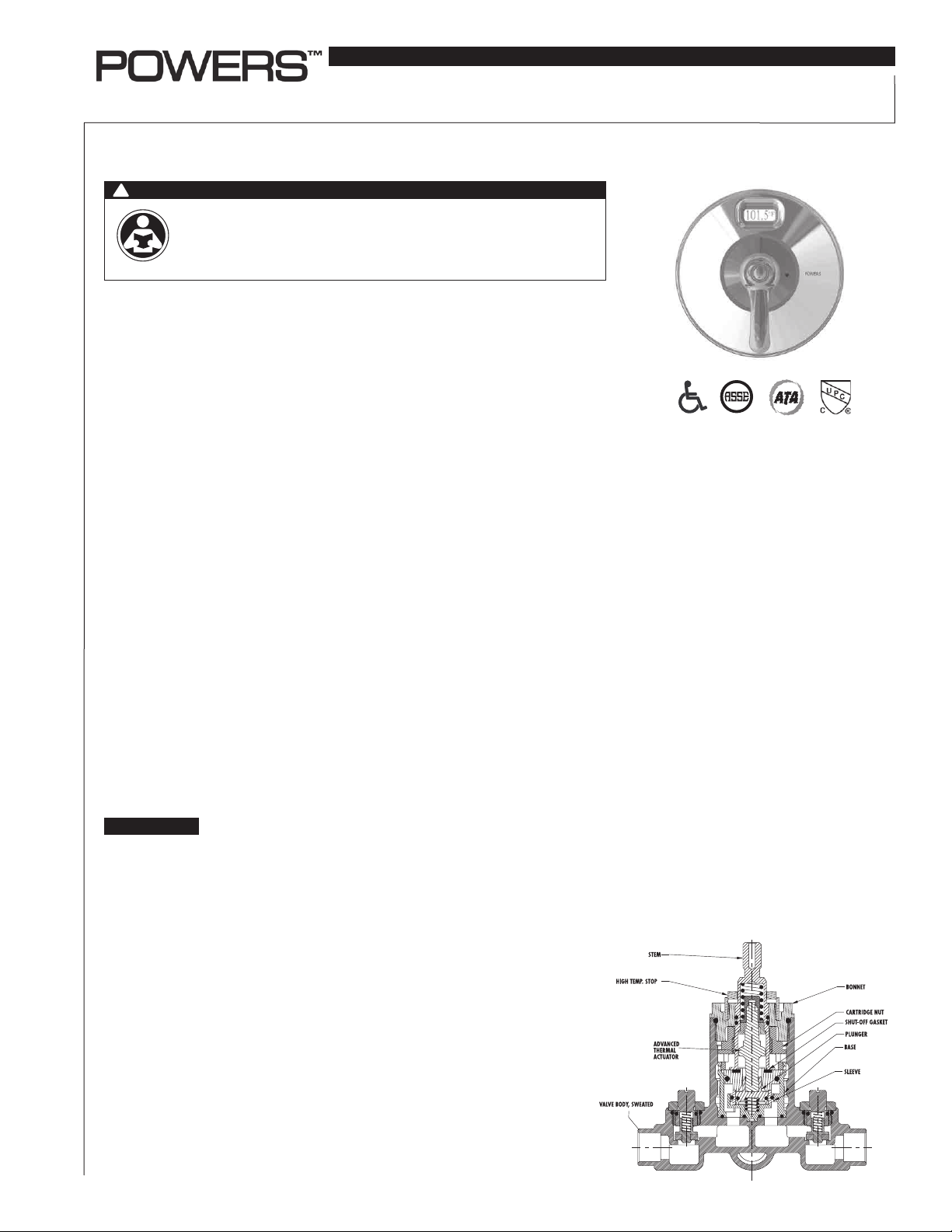
Figure 1
Operation n
Hot and cold water enter respective ports in the valve and mix in a chamber containing
an advanced thermal actuator (see Figure 1). This actuator controls the position of the
plunger and temperature. Rotating the handle repositions the plunger in the cartridge
assembly to produce the desired temperature. The mixed water passes over the shutoff
disc to the outlet. If the hot or cold supply water pressure or temperature changes,
the thermal actuator will contract or expand. The movement repositions the plunger to
maintain the desired temperature.
A high temperature limit stop restricts the movement of the handle. All F727 & C727
VisuGuard LCD T/P valves are factory set to deliver tempered water up to 110°F (43°C)
with equal pressure, with hot water temperature 140°F (60°C) and cold water temperature 60°F (16°C).
Page 2

T
!
WARNING
Figure 2
FAILURE TO COMPLY WITH PROPER INSTALLATION AND
MAINTENANCE INSTRUCTIONS COULD CONTRIBUTE TO
THE VALVE FAILURE, RESULTING IN INJURY AND/OR DEATH.
TO ENSURE THE ACCURATE AND RELIABLE OPERATION OF
THIS PRODUCT, IT IS ESSENTIAL TO:
• Properly size each valve based on the individual application.
• Properly design the recirculation system to minimize pres-
sure and temperature variations.
• Conduct an annual maintenance program to ensure proper
operation of all critical components.
• Check outlet temperature to ensure it does not exceed 110°F
(43°C). Make sure temperature limit stop is properly re-set
to maximum 110°F (43°C) following valve maintenance or
repair. Tampering with limit stop in any way may result in
scalding temperature causing serious bodily harm and/or
death.
Periodic Inspection: Corrosive water conditions, temperatures over 210°F, unauthorized adjustments or repair could
render the valve ineffective for the service intended. Regular
checking and cleaning of the valve's internal components
and checkstops helps assure maximum life and proper
product function.
Installation Instructions n
3 1/8"
3-1/8
[79]
(79)
WALL
WALL
30"
[761]
(761)
30
78" (198)
78 [1981]
APPROX. TO
APPROX. TO
FINISHED FLOOR
FINISHED
FLOOR
3 1/8"
3-1/8
[79]
(79)
WALL
WALL
12
12"
[305]
(305)
36
36"
[915]
(915)
1 5/8" (41)±
1-5/8 [41]±.25[6]
78" (1981)
78 [1981]
APPROX. TO
APPROX. TO
FINISH FLOOR
FINISHED
FLOOR
25 (6)
1. Flush all piping before installation
2. Installation and field adjustment are the responsibility of the installer
and shall be carried out in accordance to the following steps.
3. Position mixer 1-5/8" +/- 1/4" (41mm +/- 6mm) from inlet center of fin-
8 1/2 (216)
8-1/2 [216]
5 1/2 (140)
5-1/2 [140]
ish valve surface. The tub outlet port is marked "TUB" and should
face down. Facing front of the mixer, connect hot water to left side
and cold water to right side. The valve has "C" and "H" cast into the
body at the appropriate inlets ports.
!
CAUTION
When soldering during installation process, do not heat the valve any
higher than the temperature required to flow solder. Excessive overheating of the valve may cause damage to the cartridge and the checkstop internals. If either brazing or resistance (electric) solder is to be
used, all valve and checkstop internals must be removed.
!
WARNING
Figure 3
Use caution when soldering. Protect yourself and others. FUMES
AND GASES can be hazardous to your health. HEAT RAYS (INFRARED RADIATION) from flame or hot metal can injure eyes.
4. Valve is factory-set for standard inlets. If reversed inlets are required
due to back-to-back installation (cold water supply on the left and hot
water supply on the right), follow instructions 1 to 5 below:
1) Connect cold inlet to hot port (H) and hot inlet to cold port (C).
Note: Do not turn valve upside down, water will not flow properly
through tub spout or showerhead.
emperature
probe
2) Turn water off with checkstops, remove bonnet and cartridge.
3) Reinstall cartridge. "H" on the cold side of the valve body and "C"
should be on the hot side of the valve body.
5/16’’ 1/16’’
4) Reinstall bonnet with the high temperature limit stop on it.
Note: Be certain that valve opens in full cold.
5) Hot and cold inlets should be re-identified for reversed inlets to
avoid confusion during future maintenance.
5. See Figure 2, for proper piping arrangement.
6. For both shower only and shower/tub arrangements, top outlet "S" is
plugged.
2
Page 3

Installation Instructions (Cont.) n
HIGH TEMP. STOP
Thermistor Assembly
7. Locate and insert the thermistor (temperature probe) into the supplied compression outlet. See Figure 3 for the probe depth. Improper
installation of depth probe can result in imprecise temperature readings. Firmly tighten to prevent leakage. Do not hang trim plate on
wall using temperature probe wire as this could cause damage to
probe. Pressurize and test the system to verify zero leakage.
8. When piping installation is completed and before doing the finished
wall, slide rough-in guide on to the valve stem and press fit into place
(Figure 4). The rough-in guide will ensure the proper size opening for
valve, shutting off checkstops and and repair accessibility.
9. Attach indicator gasket to the back of the trim plate making sure
diagonal holes on the gasket matches diagonal holes on the trim
plate and locator hole matches the top hole on the trim plate. Peel
off backing of the trim plate gasket and attach to the inside top edge
of the trim plate.
10. Install trim plate.
Figure 4
3-3/4 [95]
3 3/4 (95)
11. Maximum Temperature Setting
Maximum temperature setting adjustment (see Figure 5) must be set
on the job and in no case it should be greater than 110°F (43°C). The
high temperature limit stop is located on the bonnet. Rotate handle
to the maximum desired outlet temperature. With an open-end
wrench, screw high temperature limit stop into the bonnet until it
touches stem's shoulder. Close valve and open it to full hot position
to verify setting.
12. Snap on the indicator plate. Guide on the back of the plate goes into
the locator hole.
13. Install sleeve O-ring on the bonnet. Slide sleeve on the bonnet.
!
CAUTION
Indicator plate must be installed before sleeve.
14. Install handle and tighten the setscrew.
Figure 5
5 [127]
5 (127)
1-5/8 ±.25"
1 5/8 (25)
Preventative Maintenance n
!
WARNING
Before servicing checkstops, always turn off the upstream water supply. When servicing valve, turn off water supply upstream or close the
checkstops.
Every Three Months:
1. Check the maximum temperature setting. Refer to Step 11 of installation instruction section.
Every Twelve Months
1. Open up the checkstops and check for the free movement of the
poppet. To access the checkstop, remove the handle and trim
plate.
2. Remove the valve bonnet and rinse all grit and impurities from the
cartridge.
Winterize valves that are used outdoors. Remove and store the internal
components and drain all water from the valve.
STEM
Safety Guidelines n
Adherence to these guidelines and recommendations promotes safe
product use and ensures proper valve performance.
1. Thermostatic valves are control devices which must be cleaned
and maintained on a regular basis. Powers specifies periodic maintenance at least once a year or immediately after any changes are
made to the plumbing system. Annual cleaning is recommended,
however, frequency of cleaning depends on quality of local water
conditions.
2. The high temperature limit stop setting must be adjusted to limit the
distance the user can rotate the handle towards the full hot water
position.
3
Page 4

Troubleshooting n
What to look for if:
• The maximum temperature cannot be obtained:
1) Lime deposits may have accumulated in the hot water pipes,
restricting the hot water supply.
2) The hot water supply temperature may be too low.
3) The temperature limit stop may be set too low. Remove handle
and re-adjust temperature limit stop (refer to step 9 of installation
instruction section).
• Flow of water is less than desired:
1) The upstream supply valves may not be fully open.
2) The inlet supply pressure(s) may be low.
3) The showerhead may be clogged.
• The valve opens with hot water ow rather than cold water ow:
1) The inlet water supplies are connected to the wrong ports or cartridge is installed improperly (see section on reversed inlets).
Parts List n
4
The tempered water is too cold, although cartridge has been replaced,
or the hot water temperature is below 115°F:
1) Raise the temperature of the hot water supply.
Flow of water is completely shut off:
1) The upstream supply valve may be completely closed.
2) The hot or cold water pressure may be failed. The valve is
designed to close down upon cold water supply pressure failure.
3) The checkstops may be closed. Open checkstops by turning the
adjustment screw fully counterclockwise.
Temperature does not display:
1) Replace battery
5, 6
2
Index Description Part #
1
3
7
8
1 Checkstop Kit 900 050
2 Cartridge Kit 220 060
3 Sleeve Kit 220 054
4 LCD Kit 727 013
5 Trim Plate & LCD Kit, Fahrenheit 727 014
6 Trim Plate & LCD Kit, Celsius 727014C
7 Trim Plate Cover 220 076
8 Handle Kit 220 079
WARNING: This product contains chemicals known to the
State of California to cause cancer and birth defects or
other reproductive harm.
For more information: www.watts.com/prop65
Warranty n
The Seller warrants that the equipment manufactured by it and covered by this order or contract is free from defects in material and workmanship and, without
charge, equipment found to be defective in material or workmanship will be repaired, or at Seller’s option replaced F.O.B. original point of shipment, if written
notice of failure is received by Seller within one (1) year after date of shipment (unless specifically noted elsewhere), provided said equipment has been properly
installed, operated in accordance with the Seller’s instructions, and provided such defects are not due to abuse or decomposition by chemical or galvanic action.
THIS EXPRESS WARRANTY IS IN LIEU OF AND EXCLUDES ALL OTHER WARRANTIES, GUARANTEES, OR REPRESENTATIONS, EXPRESS OF IMPLIED. THERE ARE
NO IMPLIED WARRANTIES OF MERCHANTABILITY OR OF FITNESS FOR A PARTICULAR PURPOSE. The Seller assumes no responsibility for repairs made on the
Seller’s equipment unless done by the Seller’s authorized personnel, or by written authority from the Seller. The Seller makes no guarantee with respect to material
not manufactured by it.
A Watts Water Technologies Company
IS-P-F727_C727 1329 EDP# 6512318 © Powers 2013
USA: Phone: 1.800.669.5430 • Fax 1.847. 229.0526 • www.powerscontrols.com
Canada: Phone: 1.888.208.8927 • Fax 1. 888.479.2887 • www.powerscontrols.ca
 Loading...