

Page 1
Technical Instructions
Description n
Powers Flowrite II Water Mix (MI) Valves combine hot and
cold water proportionally to satisfy the demands of the controlling instrument.
The valve's linear inherent characteristic produces equal
changes in flow per unit of valve stroke regardless of plug
position. The valve is air operated and can be used in a variety of mixing applications.
Specifications n
VALVE
Body Sizes: ................................ 2 1/2" – 6"
Body Material: .......................... Cast Iron
(per ASTM A126-93 Class B)
End Connectors: ....................... 125 # Flanged
(per ASNI B16.1-1993)
Trim: ........................................... Bronze
Packing: ..................................... Spring loaded TFE packing
Seat Leakage: ........................... ANSI Class III; <0.1% leakage
Cv Range: .................................. 74-390
Rangeability: ............................. 100:1
Characteristics: ........................ Linear/Mixing
Maximum Pressure: ................ 200 psi @ Temp. <150°F
Max. Differential Press.: ......... 50 psi
Temperature Range: ................ 40 – 281° F
ACTUATOR
Housing Construction: ............. Die cast aluminum
Diaphragm Construction: ........ Replaceable molded neoprene
Diaphragm Area: ...................... 46 in2, 100 in
Maximum Press. and Temp: .. 35 psi and 200°F
Ambient Shipping Limits: ........ -40 to 220° F
Ambient Operating Limits: ...... -20 to 220° F
Air Connection: ......................... 46 in2 1/4" NPT
100 in2 1/8" FNPT
Position Indication: .................. 1/8" increments
Mounting: .................................. In any upright position with
actuator head above 45° of the
center line of the valve body.
Actuator head may be swiveled
to any convenient position.
Table of Contents n
Description ..................................................... 1
Specifications ................................................ 1
Application Information ............................... 2
Theory of Operation ..................................... 2
Valve Sizing and Selection ...................... 3-4
Close Off Data ................................................ 5
Temperature/Pressure Ratings ................. 5
Dimensional Data ......................................... 6
Installation ...................................................... 7
Maintenance ................................................. 7
Ordering Information .................................... 8
2
IS-P-596MI
Flowrite II
Iron Body Series 596 MI
596 MI with 46 in2 actuator shown
Sizes Actuators Available
2 1/2" 46 in 2 or 100 in 2 Diaphragm
3" 46 in 2 or 100 in 2 Diaphragm
4" 46 in
5" 100 in 2 Diaphragm
6" 100 in 2 Diaphragm
!
WA R N I N G
FAILURE TO COMPLY WITH PROPER INSTALLATION AND
MAINTENANCE INSTRUCTIONS COULD CONTRIBUTE TO
THE VALVE FAILURE.
Watts Hot Water Master Tempering Valves cannot be used
for tempering water temperature at fixtures. Severe bodily
injury (i.e., scalding or chilling) and/or death may result
depending upon system water pressure changes and/or
supply water temperature changes. ASSE standard 1016,
1069 or 1070 listed devices should be used at fixtures to
prevent possible injury.
The Watts Hot Water Tempering Valves are designed to be
installed at or near the boiler or water heater. They are not
designed to compensate for system pressure fluctuations
and should not be used where ASSE standard 1016, 1069 or
1070 devices are required. These Watts valves should never
be used to provide “anti-scald” or “anti-chill” service.
The components of the system must be of materials with a
construction capable of withstanding the high limit output
temperatures of the water heating source.
!
WA R N I N G
Need for Periodic Inspection: Periodic inspection by a
licensed contractor is recommended. Corrosive water
conditions, temperatures over 210°F, and or unauthorized
adjustments or repair could render the valve ineffective
for service intended. Regular checking and cleaning of the
valve’s internal components and check stops helps assure
maximum life and proper product function. Frequency of
cleaning and inspection depends upon local water conditions and water temperature.
2
or 100 in 2 Diaphragm
Page 2
Application Information n
Flowrite II 596MI Valves are used for mixing hot and cold-water
streams or bypassing flow with the valve in the return line. The
controlling instrument positions the mixing valve to obtain the
approximate mixture temperature.
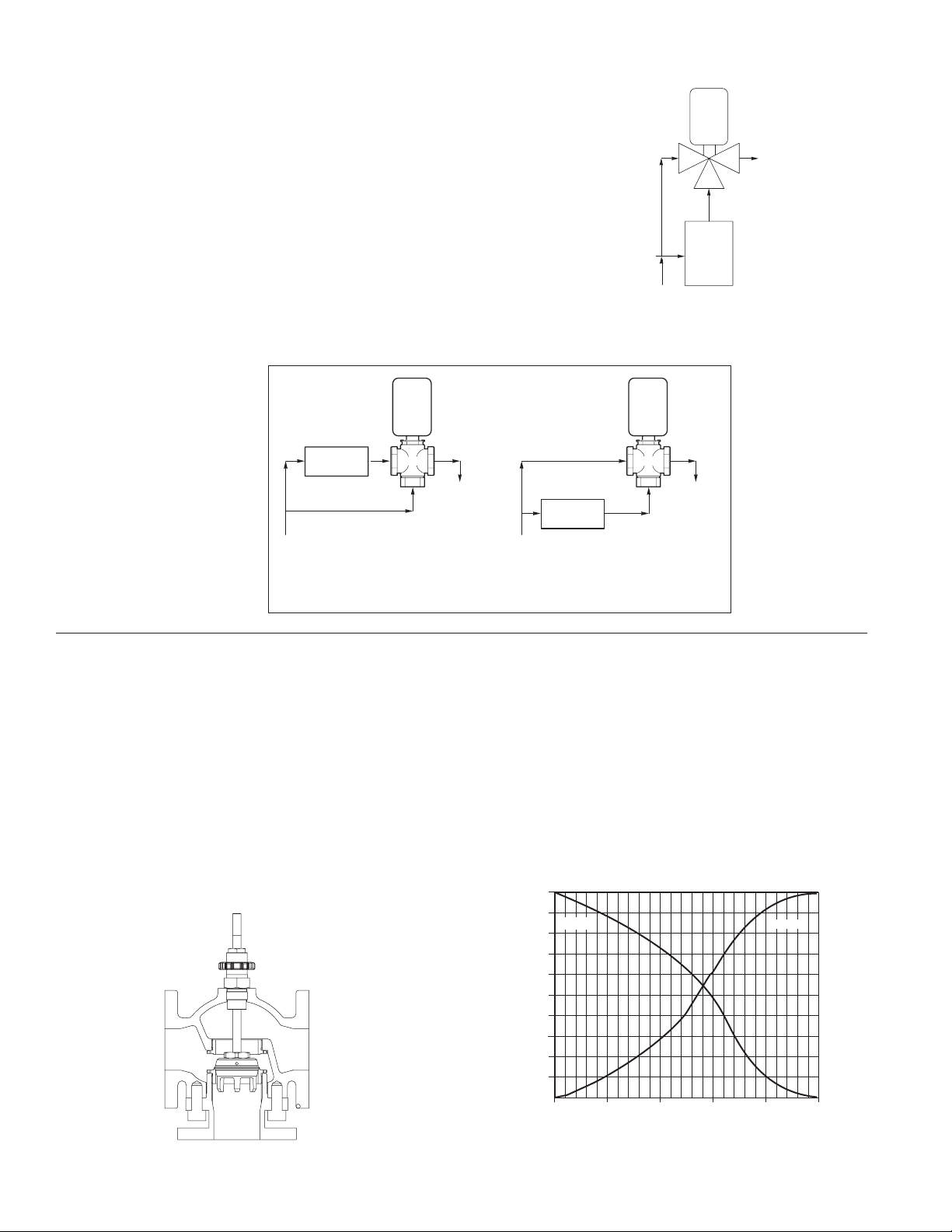
Figure 1 shows an example of a mixing application, a typical
boiler hot water control system. The cold inlet supply is fed to
the upper inlet port (A port) of the valve as well as through the
boiler for production of hot water to be fed into the bottom port
(B port).
Figure 2 shows an example of a bypass application, piping for
control of a heating or cooling coil, with the valve in the return
line. The controlling instrument positions the valve so that the
hot water will bypass the coil when the air is at the proper temperature. A pump is recommended in the coil loop to improve
the heat transfer characteristics of the coil.
Coil
Bypass
Supply Supply
Stem down flow through coil.
Stem up flow through coil bypass.
Valve
Return
Figure 1
Cold Water
Supply
Boiler Hot Water Control System
Figure 2
Bypass
Coil
Stem up flow through coil.
Stem down flow through coil bypass.
Control
Valve
Return
A AB
B
Hot Water Inlet
Boiler
Valve
Return
Bypass Piping for Control of a Heating or Cooling Coil
Theory of Operation n
Air pressure from the controlling instrument enters the pressure
tight chamber of the actuator between the diaphragm and the
upper housing. An increase in control air pressure causes the
diaphragm to press down on the thrust plate, compressing the
springs and moving the valve stem downward. In the valve, this
reduces the flow through the "B" port and increases the flow
through the "A" port.
Conversely, A decrease in control air pressure reduces the
downward force on the actuator diaphragm, moving the
thrust plate and stem upward. The flow through the "B" port is
increased, and the flow through the "A" port is decreased.
Figure 3
A
B
Three-way valve
AB
In temperature mixing applications the hot inlet is usually
plumbed to the "A" side port, which will close on loss of signal.
Otherwise, the "B" lower port is used for hot, "A" upper side port
for cold, and the "AB" outlet for the mixed combination (see
Figure 3).
Three-way mixing valves are designed so that the flow from
either of the inlet ports to the outlet is approximately linear,
which means the total flow from the outlet is almost constant
over the stroke of the valve stem. See Figure-4 for typical flow
characteristics of 596 MI.
Figure 4
100%
90%
"A" Port
80%
70%
60%
50%
40%
Rated Flow
30%
20%
10%
0%
0%
20%
40%
StrokeStem In
60%
Rated Flow vs Stroke Diagram
2
"B" Port
80%
Stem Out
100%
Page 3

Valve Sizing and Selection n
NOTE: Supply pressures (inlet) are affected by piping sched-
ule, internal surface conditions, and vertical runs (back pressure) so the actual flowing pressure is best measured at the
point of valve use.
Proportional to Mix Supply Flows
Proportional valves when used to blend two water flows control the output by varying the water temperature to the heat
exchanger at constant flow. These valves require high pressure drops for good control results. They can be sized for a
pressure drop of 20% of the flowing pressure or equal to 25% of
the pressure drop through the heat exchanger at full flow.
Table - 1 Water Capacity in Gallons Per Minute
Valve Cv
Size Rating Differential Pressure (∆ in psi)
5 10 15 20 25 30 35 40 45 50
2.5 74 165 234 287 331 370 405 438 468 496 523
3 101 226 319 391 452 505 553 598 638 678 714
4 170 380 538 658 760 850 931 1006 1075 1140 1202
5 290 648 917 1123 1297 1450 1588 1716 1834 1945 2051
6 390 872 1233 1510 1744 1950 2136 2307 2467 2616 2758
Proportional to Bypass Flow
Proportional mixing valves when used to bypass flow are piped
on the outlet side of the hot water source to throttle the water
flow and thereby control heat output. These valves are usually
selected to take a pressure drop up to 50% of the flowing pressure through the valve.
3
Page 4

Valve Sizing and Selection cont. n
Cavitation, Flashing and Choked Flow:
Limitations on Valve Pressure Drop
A concern in high temperature water systems is the potential
for cavitation, which is caused by the downstream pressure
being lower than that of the vapor pressure of the fluid. This
basically causes the water to "boil" and can result in reduced
flow/capacity, excessive noise, vibration, wear and should be
avoided if possible. If the pressure downstream of the area
restriction rises rapidly above the vapor pressure, the vapor
bubbles will collapse violently (implode). The bubble collapse is
an affirmation of cavitation. Use the following equation below
to estimate the maximum allowable pressure drop across the
valve.
Pmax = 0.5 (P1 – Pv)
Where:
Pmax = Maximum allowable pressure drop
P1 = Absolute inlet pressure (psia)
Pv = Absolute vapor pressure (refer to psia - Table 2)
Absolute pressure = gage pressure + 14.7
Table-2 Vapor Pressure of Water
Flashing is a phenomenon where the flowing high temperature
water inlet experiences a significant pressure drop, with the
outlet pressure below the vapor pressure of the water (as in
cavitation) and is converted to a vapor within the control region
of the valve.
This can also produce a choked flow condition where the rapidly expanding vapor prohibits any increase in flow, even though
P1 (inlet) pressure is increased.
Water Vapor Water Vapor
Temp. Pressure Temp. Pressure
(°F) (psia) (°F) (psia)
40 0.12 140 2.89
50 0.18 150 3.72
60 0.26 160 4.74
70 0.36 170 5.99
80 0.51 180 7.51
90 0.70 190 9.34
100 0.95 200 11.53
110 1.28 210 14.12
120 1.69 220 17.19
130 2.22 230 20.78
4
Page 5

Close Off Data n
Varying the preload is possible to adjust close offs between the upper and lower ports.
Table 3 - Close Off Data
Close Off ( ∆ P in psi)
Signal-to-Actuator
Valve Size Actuator (Positioner)
(in) Size (in2) 3-15 PSI 1-17 PSI 0-30 PSI
Upper Port Lower Port Upper Port Lower Port Upper Port Lower Port
2.5 46 8 8 27 27 73 73
100 (1M) 13 98 55 125 55 125
3 46 3 3 16 16 48 48
100 (1M) 6 66 35 94 35 125
4 46 0 0 6 6 24 24
100 (1M) 1 34 17 50 17 125
5 100 (1M) 0 21 9 31 9 97
6 100 (1M) 0 13 5 20 5 66
Temperature/Pressure Ratings n
Never exceed the temperature/pressure ratings of the valve (see figure 5). The shaded
area shows the acceptable region.
Figure 5
596MI
Temperature — F
Pressure — psig
Temperature and Pressure Ratings
5
Page 6

Dimensional Data n
Table-4 Dimensions for 596MI Series Valves
Nominal Pipe Size 2-1/2" 3" 4" 5" 6"
A 8.500 9.500 11.500 13.000 14.000
STROKE 0.875 0.875 0.875 1.750 1.750
B 5.375 6.375 8.500 8.750 9.750
C 3.500 3.750 4.500 5.000 5.875
D 10.375 10.375 10.375 N/A N/A
E 10.000 10.000 10.000 N/A N/A
F 16.625 16.625 16.625 19.000 19.000
G 10.313 10.313 10.313 10.313 10.313
Valve Weight (lbs) 62.00 82.00 115.00 180.00 264.00
Weight w/46" 75.00 95.00 128.00 N/A N/A
Weight w/100" 87.00 107.00 140.00 205.00 289.00
Figure 6
100" Actuator
G
E
F
C
B
46" Actuator
D
A
2-1/2" to 6" Valve Bodies
Table - 5 Flange Detail for American Standard 125 lb. Cast Iron Pipe Flanges
Flanges Drilling Bolting Length of
Valve Flange Flange Diameter of Diameter of Number Diameter Machine
Size Diameter Thickness Bolt Circle Bolt Holes of Bolts of Bolts Bolts
A B C D E
2-1/2" 7" 11/16" 5-1/2" 3/4" 4 5/8" 2-1/2"
3" 7-1/2" 3/4" 6" 3/4" 4 5/8" 2-1/2"
4" 9" 15/16" 7-1/2" 3/4" 8 5/8" 3"
5" 10" 15/16" 8-1/2" 7/8" 8 3/4" 3"
6" 11" 1" 9-1/2" 7/8" 8 3/4" 3-1/4"
Figure 7
E
D
B
C
A
6
Page 7

Installation n
Inspection
Inspect the package and contents for damage. If damaged,
notify the appropriate carrier immediately.
If consultation is necessary, please contact Powers Customer
Service for assistance.
Requirements
• Pipe wrenches
• Flange gaskets, bolts / nuts
• Installer must be a qualified, experienced technician
Mounting / Orientation
1. The valve should be mounted in a location that is within the
ambient limits of the actuator. When selecting a location,
allow sufficient room for valve linkage, actuator, and other
accessories and for service of the product.
2. The preferred mounting position for the valve is with the valve
stem vertical above the valve body. Avoid mounting the valve
so that the valve stem is below horizontal.
3. The valves must be piped with two inlets ("A" and "B" ports)
and one outlet ("AB" port).
CAUTION!
• Install the valve with the flow in the direction of the flow
arrows ("A" and "B" ports are inlets and "AB" port is the outlet).
• Do not exceed the ratings of the device.
• Avoid locations where excessive moisture, corrosive fumes, or
vibration are present.
Flanged Connection
The 596 series flanged valve bodies conform to ANSI Standard
125 Lb. Cast Iron Pipe Flanges. The companion flanges (not
provided) should be the same specification as the valve. The
125 Lb. Flanges have plain flat faces and should not be bolted to
a raised faced flange.
1. All parts should be clean to assure the best results.
Figure 8 - Installation of Flanged End Valves
2. The pipe with the companion flanges installed should be
properly supported and aligned. Be sure the companion
flange is flush with the face of the valve body flange and lined
up squarely.
3. Use a gasket material (not provided) that is recommended
for the medium being handled. CAUTION! Do not apply pipe
dope to the valve flange, gasket, or companion flange.
4. See Figure-7 for flange and flange bolt details. Figure-8
Valve
Body
Gasket:
Supplied by Others
Companion
Flange
shows the proper way a flanged valve should be mounted.
Maintenance n
Regular maintenance of the total system is recommended to assure sustained performance. See Table-6 for maintenance kit part numbers.
Table - 6 Maintenance Kits for 596MI Valves
Valve Description Replacement Replacement Valve Repair Kit*
Pack Assembly Gaskets
2.5 596 Pack 596250G MIGOBMTK
3 596300G MIHOBMTK
4 596400G MIJOBMTK
5 596500G MIKOBMTK
6 596600G MILOBMTK
* Kit includes replacement packing and stem & plug assembly.
Water System Maintenance
All systems are susceptible to valve and system problems caused
by improper water treatment and system storage procedures.
These guidelines are provided to help avoid valve and water system problems resulting from improperly treated water or storage
procedures and to obtain maximum life from the valves.
To maintain non-damaging conditions, follow these guidelines:
• Clean the system prior to start up.
• Use filtration equipment where needed.
• Properly store off-line systems and monitor water treatment
results.
• Follow the advice of a water treatment professional.
Durability of valve stems and packings is dependent on maintaining non-damaging water conditions. Inadequate water treatment
or filtration can result in corrosion, scale, and abrasive particle
formation. Scale and particulates can result in stem and packing
scratches and can adversely affect packing life and other parts
of the hydronic system.
7
Page 8

Ordering Information n
M I
596-
Size Order Code
2 1/2" 250
3" 300
4" 400
5" 500
6" 600
End Connections
125# Flange F
Valve Trim
Bronze B
Action
Mixing M
Packing
Teflon T
Actuator Select Code n
Code Pneumatic Diaphragm Actuators
46 46 Sq. in, 1" Max Valve Stroke with Stainless Steel Springs,
adjustable start w/ 7 ~ 12 lb. Fixed span
4X 46 Sq. in, 1" Max Valve Stroke with Extended Springs
(requires positioner), adjustable start w/22 lb. span.
1M 100 Sq. in, 5-10 psi Spring Range (Mixing Valves)
Accessories Select Code n
Code Description
Bellofram 1000 I/P’S
IS 3–15 psi
TS 1–17 psi
US 3–27 psi
Control/Air Type 900X I/P
ES 0–30 psi
Utility Positioner and I/P
BS 4–20 mA
Utility Positioner
PS 3–15 psi
RS 3–9 psi
SS 9–15 psi
No Accessories
OS No Accessories
Accessories
Select Code
(see below)
Actuator
Select Code
(see below)
I/P Transducers n
The "standard" 3-15 psi signal was originally designed as a transmission signal, not a valve actuation signal. The Fluid Controls
Institute (in Standard 87-2) has recommended that a 1–17 psi
air signal range be used when directly actuating a control valve
without a positioner. Powers concurs with this recommendation, and therefore, offers a 1–17 psi I/P transducer and a 0–30
psi I/P transducer and the Accritem pneumatic controller for
maximum close-off. 3-15 psi I/P transducers should be used in
conjunction with positioners.
Positioners n
Positioners are used for one or more of the following reasons:
1) To split range valves.
2) To eliminate unwanted valve movement caused by line pressure variations
3) To minimize the effects of "stick-slip"
4) To speed response time and/or
5) To increase close-off rating when I/Ps are used.
Warranty n
The Seller warrants that the equipment manufactured by it and covered by this order or contract is free from defects in material and workmanship and, without
charge, equipment found to be defective in material or workmanship will be repaired, or at Seller’s option replaced F.O.B. original point of shipment, if written
notice of failure is received by Seller within one (1) year after date of shipment (unless specifically noted elsewhere), provided said equipment has been properly
installed, operated in accordance with the Seller’s instructions, and provided such defects are not due to abuse or decomposition by chemical or galvanic action.
THIS EXPRESS WARRANTY IS IN LIEU OF AND EXCLUDES ALL OTHER WARRANTIES, GUARANTEES, OR REPRESENTATIONS, EXPRESS OF IMPLIED. THERE ARE
NO IMPLIED WARRANTIES OF MERCHANTABILITY OR OF FITNESS FOR A PARTICULAR PURPOSE. The Seller assumes no responsibility for repairs made on the
Seller’s equipment unless done by the Seller’s authorized personnel, or by written authority from the Seller. The Seller makes no guarantee with respect to material
not manufactured by it.
A Watts Wat er Technologies Company
IS-P-596MI 1043 EDP# 6512249 © 2010 Powers
USA: Phone: 1.800.669.5430 • Fax 1.847. 229 . 0526 • www.powerscontrols.com
Canada: Phone: 1.888.208.8927 • Fax 1. 888 .479. 2887 • www.powerscontrols.ca
 Loading...