

Page 1

• Up to 1380 lbs. of
force
• Excellent range
control
• Accurate repetitive
positioning
• Dual NAMUR
Accessory Mounts
• Field Reversible
• “Long-life” design
lasts over one
million cycles
46” Actuator
Powers’ most popular actuator is
powerful, durable, and versatile.
TABLE OF CONTENTS
Features . . . . . . . . . . . . . . . . . . . . . . . .2
Description . . . . . . . . . . . . . . . . . . . . .3
Guide to Applications . . . . . . . . . . . . .3
Operation . . . . . . . . . . . . . . . . . . . . . .3
Installing an Actuator . . . . . . . . . . . . .4
Changing Springs . . . . . . . . . . . . . .4-5
Changing Action . . . . . . . . . . . . . . .6-7
Preload . . . . . . . . . . . . . . . . . . . . . . . .8
Replacing a Diaphragm . . . . . . . . .9-10
Parts List . . . . . . . . . . . . . . . . . . .11-13
Spring Range Matrix . . . . . . . . . . . . .13
Modification Data Table . . . . . . .14-16
TI-593-672
Page 2
2
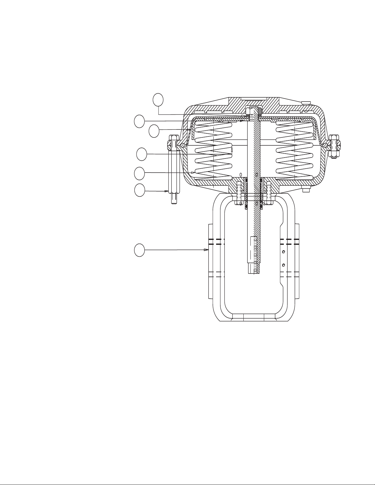
1. Optional stainless steel springs
extend operating life to over
one million cycles.
2. Nested spring design creates a
uniform stroke by eliminating
spring side flex.
3. 316 Stainless steel thrust
plate is corrosion resistant.
4. All stainless steel hardware
used in combination with SS
spring makes long-life
standard.
5. Molded fiber and reinforced
diaphragm greatly reduces the
risk of stress cracks.
6. Rolling diaphragm design
allows for even pressure
during the stroke cycle
making for more precise
control.
7. Field reversible design makes
changing the fail-safe mode
possible.
8. With *extended nut hardware,
preload can be safely released
for inspection.
9. Dual NAMUR mounts can be
used to quickly add or
reorient accessories.
FEATURES
*
5
3
6
2
1
8
9
Page 3

DESCRIPTION
Powers’ most popular actuator, the ‘46’, is a versatile, field reversible
design that is available on most Flowrite II valves. This actuator
provides:
• large effective area (1380 lbs of force at 30 psi) for powerful
valve close control
• excellent narrow range control signal performance
• accurate repetitive positioning due to large diameter
diaphragm, low friction actuator stem and bronze bearings, and
• dual NAMUR accessory mounts.
The 46 actuator and Flowrite II valves are designed to integrate intro a
highly flexible system. It is possible through the Flowrite II 46”
actuation system to adapt to changing application requirements by
reconfiguring the actuator through simple spring changes, stem
changes, etc. The purpose of these instructions is to suggest solutions
to meet your applications needs.
OPERATION
The actuator springs provide the necessary force to hold the stem in
the lowered or raised position.
On a Normally Open valve (ATC, D/A) assembly, the stem will
start its downward stroke whenever the control air pressure applied
against the actuator diaphragm area and upper housing exceeds the
holding force of the springs.
A further increase in control air pressure will initiate a continued
downward travel of the valve stem until the valve has completed its
stroke.
On a Normally Closed valve (ATO) assembly, the valve stem will
start its upward stroke whenever the control air pressure applied
against the actuator diaphragm area and the lower housing exceeds
the holding force of the springs.
A further increase in control air pressure will initiate a continued
upward travel of the valve stem until the valve has completed its
stroke.
The air pressure change to initiate full stem travel is known as the
throttling range or spring span. Standard spring span is equal to 8
psi (55 kPa) with no drop across the valve.
This throttling range is based on typical system pressure and will
vary slightly as the pressure drop across the valve changes. A
decrease in pressure at the diaphragm will initiate an upward
movement on a normally open valve assembly and a downward
movement on a normally closed valve assembly.
When the valve is at its wide open position, the disc and throttling
plug are farthest from the seat and there is maximum flow through
the valve.
Valve actuators equipped with a pilot positioner can utilize full
control air pressure at any point in the stem travel to initiate stem
movement or to maintain stem position.
However, the actuator springs still provide the necessary force to
move the stem in the opposite direction.
Use of a positioner will tend to provide faster response and to ensure
repeatability of stem position regardless of the load on the actuator.
However, in a system where available pressure and flow
requirements are relatively consistent, control valves can usually
perform adequately without a positioner.
GUIDE TO APPLICATIONS
To reverse actuator action, i.e., change an NO to an NC valve,
or an NC to an NO valve:
1. Refer to the Modification Tables for correct replacement parts.
2. Follow instructions for Reversing Actuator Action.
3. Follow instructions for Preload Adjustment.
To attempt valve sequencing with a 3-15 psi air signal OR to set
a NC valve assembly at a higher preload to maintain closeoff or
to increase the throttling range:
1. Refer to the Modification Tables for correct replacement parts.
2. Refer to Changing Springs.
3. Follow instructions for Preload Adjustment.
4. Use dimensions in the Spring Range Matrix.
To modify the actuator action, i.e., using the same actuator on a
different valve body or size:
1. Refer to Modification Tables for correct replacement parts.
2. Refer to Changing Springs.
3. Refer to Changing Action (changing stems).
4. Follow instructions for Preload Adjustment.
5. Use dimensions in the Spring Range Matrix.
To install an actuator on a valve and set the preload adjustment:
1. Follow Installing Actuator instructions.
2. Refer to Modification Tables for correct replacement parts.
3. Follow instructions in Preload Adjustment.
To replace a ruptured diaphragm:
1. Refer to Replacing the Diaphragm instructions.
3
Page 4
4
CHANGING SPRINGS (DIRECT ACTING ACTUATORS)
Springs can be changed or added if a higher shutoff rating is
required. This may become necessary under the following
conditions:
1. If the pressure of the medium passing through the valve increases,
2. If the valve size increases due to an increase in process demand, or
3. If valve body type is changed.
The Modification Data Tables (page 13-15) provide dimensional
data including part numbers, and number of springs required to
reconfigure an actuator.
Springs may be changed with the actuator assembled or removed
from the valve. For ease of instruction, pictures are shown with
actuators removed.
To change or add springs on a Direct Acting (DA, NO, ATC)
actuator assembled to the valve, follow steps 1, 2, 3, 4A, 5-10.
To change or add springs on a Direct Acting (DA, NO, ATC)
actuator removed to the bench, follow steps: 1-4A, 5-9.
To change or add springs on a Direct Acting (DA, NO, ATC)
actuator assembled to the valve and under preload, follow steps:
1, 3, 4B, 5-10.
1. Shut off controlled medium supply (steam, water, or other
liquid).
2. Reduce preload on the springs (refer to Decreasing Preload
on DA Actuators pg. 7).
3. Remove the control signal to the actuator.
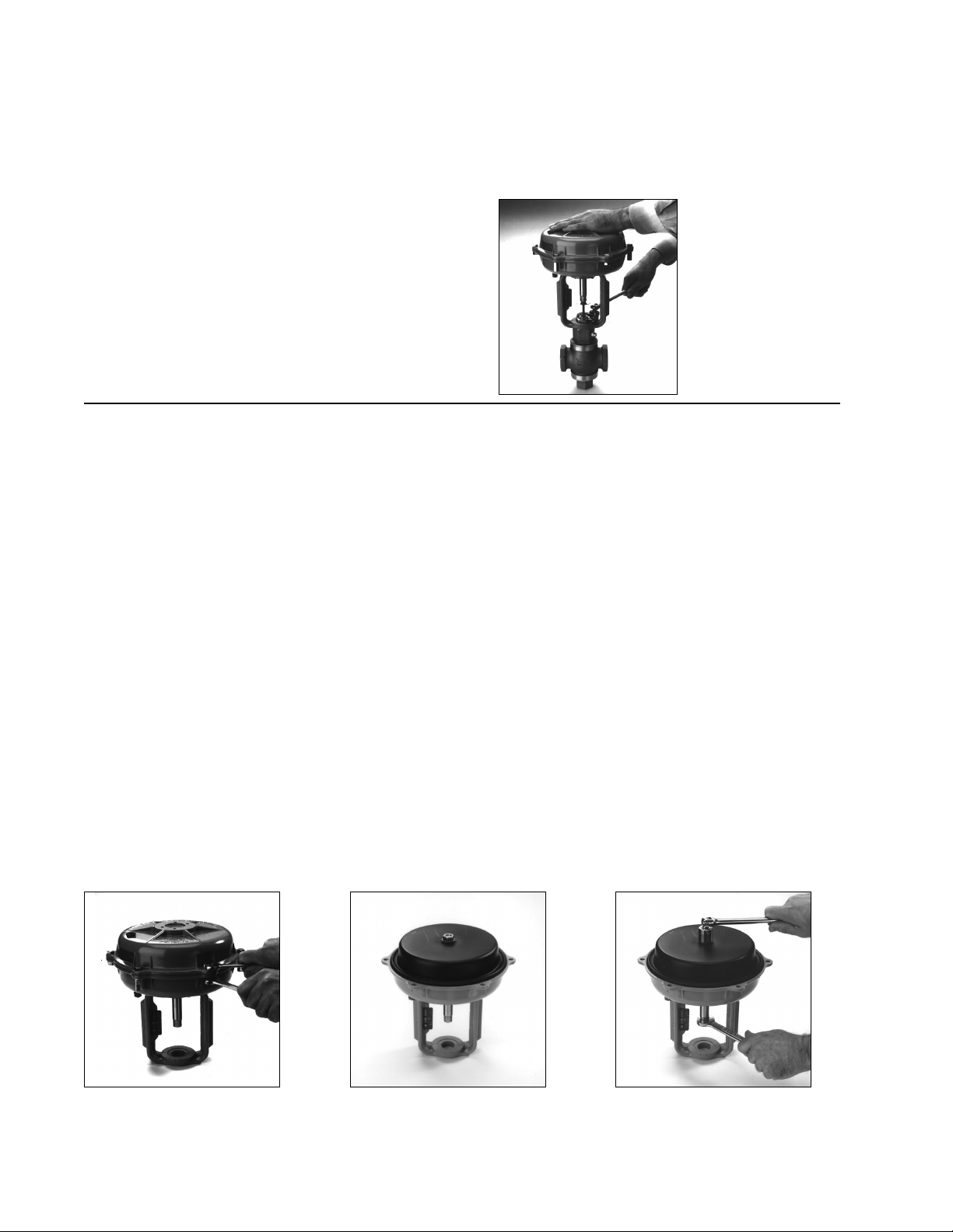
4A. (Fig. 1) Remove top housing nuts and bolts or (see above)
4B. (Fig. 1) Remove the three bolts attached to the short nuts,
then equally release the bolts attached to the long nuts.
CAUTION: Springs under tension.
5. (Fig. 2A) Remove upper housing.
6. Remove stem nut, silver and black washers (Fig. 2B).
7. Remove diaphragm, and thrust plate (Fig. 2C).
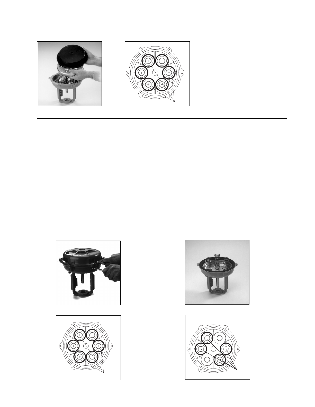
8. Change or add springs as needed (Fig. 3A & 3B). Make sure
the springs are properly placed over the spring guides
and their configuration is symmetrical.
9. Reassemble parts in reverse order, then attach upper housing.
10. Adjust preload ref.
NOTE: Some actuator models have small springs nested inside
the larger springs. The small springs also fit over spring guides
and must also be placed symmetrically.
Fig 1 - Remove Housing Bolts
*(extended versions last and gradually)
Fig 2A - Remove Upper Housing
Fig 2B - Remove Stem Nut, & Washers
INSTALLING AN ACTUATOR
1. Place actuator assembly over valve stem. With actuator stem and
valve stem separated, place bonnet lock nut over valve stem onto
bonnet.
2. Apply air pressure to the actuator approximately 9 psi for a
Normally Closed valve assembly, and 3 psi for a Normally Open
Assembly.
3. Tighten the valve stem to the actuator stem by rotating the valve
stem (NOT THE ACTUATOR STEM).
4. Tighten the two locknuts together and rotate them clockwise.
Tighten the nuts to achieve the proper PRELOAD (as explained in
the Preload Section).
5. Remove air pressure.
6. Tighten the bonnet locknut on the bonnet (Fig.1).
Fig 1 - Tighten the Bonnet
Lock Nut on the Bonnet
Page 5
CHANGING SPRINGS (REVERSE ACTING ACTUATORS)
Springs may be changed with the actuator assembled or removed
from the valve. For ease of instruction, pictures are shown with
actuators removed.
To change or add springs on a Reverse Acting (RA, NC, ATO)
actuator assembled to the valve, follow steps 1-4A, 5-8.
To change or add springs on a Reverse Acting (RA, NC, ATO)
actuator removed to the bench, follow steps: 1-4A, 5-7.
To change or add springs on a Reverse Acting (RA, NC, ATO)
actuator assembled to the valve and under preload, follow steps:
1, 3, 4B, 5-8.
1. Shut off controlled medium supply (steam, water, or
other liquid).
2. Reduce preload on the springs (refer to Decreasing Preload
on DA Actuators pg. 7).
3. Remove the control signal to the actuator.
4A. (Fig. 1) Remove top housing nuts and bolts or (see above).
4B. (Fig. 1) Remove the three bolts attached to the short nuts,
then equally release the bolts attached to the long nuts.
CAUTION: Springs under tension.
5. (Fig. 2A) Remove upper housing.
6. Add or remove springs as needed for new configuration
(Fig 3A &Fig. 3B). Make sure the springs are properly placed
over the spring guides and their configuration is symmetrical.
NOTE: Some actuator models have small springs nested
inside the larger springs. The small springs also fit over
spring guides and must also be placed symmetrically.
7. Reassemble upper housing.
NOTE: Assemble bolts with long nuts first.
8. Adjust preload ref pg. 7.
Fig 1 - Remove Housing Bolts
Fig 2- Remove Upper Housing
Fig 3A - Typical 3-Spring Installation
NOTE: *Number required may vary. Refer
to page 14-15.
Fig 3A - Typical 4-Spring Installation
Fig 2C - Remove Diaphragm,
Thrust Plate
Fig 3A - Typical-Spring Installation
5
Springs
Springs
Springs
Page 6

6
CHANGING ACTION (DIRECT ACTING ACTUATORS)
All valve bodies used with Flowrite II Actuators are push-to-close.
Directing Acting actuators make the valve action Normally Open
(NO, DA, ATC); Reverse Acting actuators make the valve action
Normally Closed (NC, RA, ATO).
Changing the action of the actuator (DA to RA or RA to DA) will
therefore reverse the valve action from NO to NC, or NC to NO.
To change the actuator action, you change the stem and reverse the
order of the spring, diaphragm and thrust plate assembly.
Change Actuator Action from DA to RA or NO to ATC or NC
to ATO:
1. Shut off controlled medium supply (steam, water, or other
liquid).
2. Reduce preload on the springs (refer to Decreasing Preload
on DA Actuators).
3. Remove the control signal to the actuator.
4. Remove top housing nuts and bolts.
5. Remove upper housing. Remove stem nut, silver and black
washer. (Fig 2A).
6 Remove diaphragm, thrust plate and springs (Fig. 2B).
7. Hold the actuator stem in place and loosen the valve stem
locknuts (turn locknuts counterclockwise a number of times).
8. Hold actuator stem and tighten the two lock nuts together.
Turn the locknuts counterclockwise to rotate the valve stem
until the two stems are separated. (Fig. 3)
9. Pull actuator stem upward and remove from assembly
(Fig. 4).
10. Replace with RA actuator stem. Position stem with flats
pointing downward.
11. Thread valve stem into actuator stem by turning the locknuts
clockwise. Tighten by hand.
12. Place black washer on actuator stem. Invert diaphragm and
place inside of lower housing over the black washer. Invert
thrust plate and place on top of diaphragm. (Fig. 5)
13. Replace silver washer and tighten stem nut.
14. Place springs on thrust plate in same orientation as found in
lower housing. Properly seat springs over spring guides
(Fig. 6).
15. Replace upper housing assembly and tighten housing nuts
and bolts. (Fig. 1)
16. Connect control signal to 1/4" NPT fitting located on
bottom of actuator housing.
17. Adjust the preload per instructions on pg. 7.
Fig 1 - Remove Housing Bolts Fig 2A - Remove Upper Housing,
Stem, Nut and Washers
Fig 2B - Remove Diaphragm
and Thrust Plate
Fig 3 - Loosen Stem Locknuts
Fig 4 - Remove Stem Fig 5 - Reverse Replacement of
Diaphragm and Thrust Plate
Fig 5 - Reverse Replacement of
Diaphragm and Thrust Plate.
Four (4) springs shown. See
note on page 5.
Page 7

CHANGING ACTION (REVERSE ACTING ACTUATORS)
Change Actuator Action from RA to DA:
1. Shut off controlled medium supply (steam, water, or other
liquid).
2. Reduce preload on the springs (refer to Decreasing Preload
on RA Actuators).
3. Remove the control signal to the actuator.
4. (Fig. 1) Use a 1/2" wrench on the top housing bolts and hold
the bottom housing nuts with a 9/16" wrench.
5. (Fig. 2A) Remove upper housing.
6. Remember the orientation of springs on the thrust plate.
Remove springs, stem nut (Fig. 2B)...
7. …silver washer, thrust plate, diaphragm, & black washer
(Fig. 2C).
8. Hold the actuator stem in place and loosen the valve stem
locknuts (turn locknut counterclockwise a number of times).
9. Hold actuator stem and tighten the two lock nuts together.
Turn the locknuts counterclockwise to rotate the valve stem
until the two stems are separated. (Fig. 3)
10. Pull actuator stem upward and remove from assembly.
(Fig. 4).
11. Replace with DA actuator stem. Position stem with flats
pointing downward.
12. Thread valve stem into actuator stem by turning the locknut
clockwise. Tighten by hand.
13. Place springs in lower housing in same orientation as found
on thrust plate. Properly seat springs over the spring guides
14. Invert thrust plate and place on top of springs. Invert
diaphragm and place on top of thrust plate (Fig. 5).
15. Replace black washer, place silver washer on top of black
washer, and tighten stem nut (Fig. 6).
16. Replace upper housing assembly and tighten housing nuts
and bolts (Fig. 1).
17. Connect control signal to 1/4" NPT fitting located on the
top of the actuator housing.
18. Adjust the preload per instructions on pg. 7.
Fig 1 - Remove Housing Bolts Fig 2A - Remove Upper
Housing to Expose Springs
(4 Shown)
Fig 2B - Remove Springs,
Stem Nut
Fig 3 - Loosen Stem Locknuts Fig 4 - Remove and Replace
Stem
Fig 5 - Replace Springs,
Reversed Thrust Plate and
Diaphragm
Fig 2C - Remove Washers,
Thrust Plate, Diaphragm
Fig 6 - Replace Washers,
Tighten Stem Nut
7
Page 8

8
PRELOAD
The Normally Closed (NC, RC, ATO) valve assembly uses the
springs to hold the valve shut, against the upstream pressure
attempting to push the plug open.
1. All Normally Closed valve assemblies are factory set to a nominal
preload depending on size of 7-10 psi.
2. If your process requires a high air pressure signal (>7 psi) to start
the valve moving, it is necessary to decrease the actuator preload.
Adjust the preload so that the valve is fully closed with the
minimum air signal and fully open with the maximum air signal.
3. It is a characteristic of an unbalanced valve that as the pressure
drop across the valve increases, the effective spring range
increases. Consult one of our application engineers if you have
any questions about your particular application.
The Normally Open (NO, DA, ATC) valve assembly uses the
actuator springs to hold the valve open, and the upstream
pressure helps to hold the valve open.
1.If the maximum air signal applied to the valve does not allow the
valve to shut off tightly, decrease the preload.
2.If the valve starts closing at too low of an air signal, increase the
preload. The preload should be adjusted so that control air
pressure closes the valve tightly, and stem movement starts at an
acceptable point.
3. In some applications where a wide range of flow conditions are
encountered, it is desirable to install two valves in parallel and
sequence them.
Preload adjustment (also called spring tension adjustment) is
required under the following conditions:
1. The valve and actuator stem have been disengaged. (for packing
changes, stem changes, maintenance of valve assembly, etc.)
2. The action of the valve assembly has been reversed.
3. Valve sequencing is required. (Use of a positioner is
recommended if using a 3–15 psi control signal.)
4. Line pressure force exceeds the spring holding force on a
normally closed (NC) valve assembly, which causes the valve to
open with less than 7 psi signal preload.
5. Line pressure force adds to the spring holding force on a
normally open (NO) valve assembly, which causes the valve to
start closing at a preload greater than 3 psi signal
Deviation from this recommended preload setting will affect your
process. A higher preload setting requires a higher air signal at the
diaphragm to start stroking the valve. If the preload is too high,
with a given air signal a Normally Open valve will not close
completely, and a Normally Closed valve will not open completely
to overcome the initial preload setting.
To decrease preload on RA actuators or increase preload on DA
actuators:
1. To prevent the plug and seat from scoring, lift the valve plug off
the seat before adjusting the preload by applying air pressure to
the actuator, approximately 9 psi for a Normally Closed valve
assembly, and 5 psi for a Normally Open Assembly.
2. Hold the actuator stem in place (DO NOT turn actuator stem
during this process) and loosen the valve stem locknut by turning
the locknuts counterclockwise a number of times.Press the two
locknuts together.
3. Hold the actuator stem in place (DO NOT turn the actuator
stem), turn the valve stem clockwise and retighten the locknut.
(Fig. 1).
To increase preload on R.A. actuators or decrease preload on
D.A. actuators:
1. To prevent the plug and seat from scoring, lift the valve plug off
the seat before adjusting the preload by applying air pressure to
the actuator, approximately 10 psi for a Normally Closed valve
assembly, and 5 psi for a Normally Open Assembly.
2. Hold the actuator stem in place (DO NOT turn actuator stem
during this process) and loosen the valve stem locknuts by
turning the locknuts counterclockwise a number of times. Press
the two locknuts together.
3. Hold the actuator stem in place (DO NOT turn the actuator
stem), turn the valve stem locknuts counter-clockwise and
retighten the locknut (Fig. 1).
Fig 1 - Rotate Lock Nuts to
Adust Preload
Page 9

9
REPLACING A DIAPHRAGM (DIRECT ACTING ACTUATORS)
The diaphragm can be changed with the actuator assembled or
removed from the valve. For ease of instruction pictures are shown
with actuators removed.
To change a diaphragm on a Direct Acting (DA, NO, ATC)
actuator assemble to the valve follow steps: 1-4A, 5-9.
To change a diaphragm on a Direct Acting (DA, NO, ATC)
actuator removed to the bench follow steps: 1-4A, 5-8.
To change a diaphragm of a Direct Acting (DA, NO, ATC)
actuator assemble to the valve and under preload follow steps:
1-3, 4B, 5-9.
1. Shut off controlled medium supply (steam, water, or other
liquid) and remove the control signal to the actuator.
2. Reduce preload on the springs (refer to Decreasing Preload on
DA Actuators), see pg. 7.
3. Remove the control signal from the actuator.
4A. (Fig. 1) Remove top housing nuts and bolts or (see above)
4B. (Fig. 1) Remove the three bolts attached to the short nuts, then
equally release the bolts attached to the long nuts.
CAUTION: Springs under tension.
5. Remove upper housing (Fig. 2)
6. Remove stem nut, washer and diaphragm. (Fig. 3)
7. Place new diaphragm over thrust plate. Make sure that the lip of
the diaphragm is seated properly in the groove of the actuator
housing.
8. Reassemble in reverse order.
NOTE: Assemble bolts with long nuts first.
9. Adjust preload, refer to pg. 7.
Fig 1 - Remove Housing Bolts Fig 2 - Remove Stem Nut, and
Washers
Fig 3 - Remove Diaphragm (Leave
Thrust Plate On).
Page 10

10
REPLACING A DIAPHRAGM (REVERSE ACTING ACTUATORS)
The diaphragm can be changed with the actuator assembled or
removed from the valve. For ease of instruction pictures are shown
with actuators removed.
To change a diaphragm on a Reverse Acting (RA, NC, ATO)
actuator assemble to the valve follow steps: 1-4A, 5-10.
To change a diaphragm on a Reverse Acting (RA, NC, ATO)
actuator removed to the bench follow steps: 1-4A, 5-9.
To change a diaphragm of a Reverse Acting (RA, NC, ATO)
actuator assemble to the valve and under preload follow steps:
1-3, 4B, 5-10.
1. Shut off controlled medium supply (steam, water, or other
liquid) and remove the control signal to the actuator.
2. Reduce preload on the springs. Follow procedures for
Decreasing Preload on DA Actuators on pg. 7.
3. Remove the control signal to the actuator.
4A. (Fig 1) Remove top housing nuts and bolts or see above
4B. (Fig 1) Remove the three bolts attached to the short nuts, then
equally release the bolts attached to the long nuts.
CAUTION: Springs under tension.
5. Remove upper housing (Fig 2).
6. Remember the orientation of the springs. Remove springs, stem
nut...(Fig. 3).
7. ...silver washer, thrust plate, diaphragm, & black washer
(Fig. 4).
8. Replace with new diaphragm. Make sure the lip of the
diaphragm is seated properly in the groove of the actuator
housing.
8. Reassemble in reverse order.
NOTE: Assemble bolts with long nuts first.
10. Adjust preload, refer to pg. 7.
Fig 1 - Remove Housing Bolts Fig 2 - Remove Upper Housing, Remove
Springs (4 Shown)
Fig 3 - Remove Stem Nut...
Fig 4 - Remove Thrust Plate and Old
Diaphragm
Page 11

11
PARTS LIST - DA ACTUATOR
ITEM PART NUMBER QUANTITY PART DESCRIPTION
1 See Chart 1 Yoke (Cast Iron)
2 672-632A 1 Top Housing Machined
3 672-633A 1 Bottom Housing Machined
4 See Chart 1 Stem, D.A.
5 081-008 3 Nut, Housing
6 080-033 3 Bolt, Housing
7 672-646 See Chart Spring, Small
8 672-645 See Chart Spring, Large
9 672-626 1 Diaphragm
10 672-627 1 Thrust Plate, Steaming
11 672-618E 1 Bushing, Stem
12 084-015 2 “O” Ring
13 672-470A 1 Label Warning
14 043-009C 1 Cap Plug, 1/4”
15 082-005R 1 Washer, Stem
16 081-011 1 Nut, Stem
17 080-034 4 Bolt, Yoke
18 082-005 1 Washer, Stem
19 087-128 1 Vent Plug, 1/4” NPT
20 672-641 1 Bearing, Stem
22 672-620 1 Nameplate
23 See Chart 1 Locknut
24 900-326 3 Nut, Coupling 5/16 -18x2
25 900-327 3 Bolt, 5/16-18 x 3LG
CURRENT STD. SPRINGS STD. SPRINGS SS. SPRINGS SS. SPRINGS
ACTUATORS 672-642 672-615 672-645 672-646 STEM YOKE LOCK NUT
672022D 2 2 0 0 672-636 672-724 625-008
672033D 6 0 0 0 672-636 672-724 625-008
672044D 4 4 0 0 672-636 672-724 625-008
672601D 6 6 0 0 672-636 672-724 625-008
672602D 0 3 0 0 672-636 672-724 625-008
672603D 3 0 0 0 672-636 672-724 625-008
672604D 4 0 0 0 672-636 672-724 625-008
672605D 0 4 0 0 672-636 672-724 625-008
672606D 6 0 0 0 672-636 672-724 625-008
672607D 0 6 0 0 672-636 672-724 625-008
672651D 6 6 0 0 672-614 672-725 625-008
672653D 3 0 0 0 672-614 672-725 625-008
672654D 4 0 0 0 672-614 672-725 625-008
672655D 0 4 0 0 672-614 672-725 625-008
672656D 6 0 0 0 672-614 672-725 625-008
672657D 0 6 0 0 672-614 672-725 625-008
672666D 0 4 0 0 672-636B 672-725 625-008
672670D 0 6 0 0 672-636B 672-725 625-008
672671D 0 6 0 0 672-614B 672-725 625-008
672672D 0 4 0 0 672-614B 672-725 625-008
672726D 0 6 0 0 672-634 672-725 625-008
672727D 0 4 0 0 672-634 672-725 625-008
672728D 0 6 0 0 672-634 672-725 625-008
672-460D 0 0 0 3 672-636 672-724 625-008
672-474D 0 0 0 4 672-636 672-724 625-008
672-647D 0 0 0 6 672-636 672-724 625-008
672-474D 0 0 0 4 672-636 672-724 625-008
672-457D 0 0 0 6 672-636 672-724 625-008
672-461D 0 0 0 4 672-636 672-724 625-008
672-462D 0 0 0 6 672-636 672-724 625-008
672-463D 0 0 0 6 672-636 672-724 625-008
672-464D 0 0 0 6 672-636 672-724 625-008
672-648D 0 0 6 6 672-636 672-724 625-008
672-647D 0 0 6 0 672-636 672-724 625-008
672-474D 0 0 4 0 672-636 672-724 625-008
672-467D 0 0 4 4 672-636 672-724 625-008
672-465D 0 0 6 0 672-614B 672-725 625-008
672-466D 0 0 6 0 672-618E 672-725 625-008
672-469D 0 0 6 0 672-634 672-725 625-008
672-468D 0 0 6 0 672-634 672-725 625-008
15
18
9
2
25
24
3
10
11
1
4
Notes:
1. For other spring replacements, make sure that springs are
arranged symemtrically to ensure proper balance for the actuator.
2. Soak "O" rings in silicone oil prior to assembly.
Assemble and test per Eng. Spec. Y-672-1.
**
Apply Removable
16
Loctite Threadlocker #242
(10-12 ft.-lbs.)
"X"
13
NOT SHOWN
NOT SHOWN
22
23
NOT SHOWN
14
6
5
8
7
19
(10-12 ft.-lbs.)
17
20
**
12
Page 12

12
PARTS LIST - RA ACTUATOR
"X"
ITEM PART NUMBER QUANTITY PART DESCRIPTION
1 See Chart 1 Yoke (Cast Iron)
2 672-632A 1 Top Housing Machined
3 672-633A 1 Bottom Housing Machined
4 See Chart 1 Stem, D.A.
5 081-009 3 Nut, Housing
6 080-033 3 Bolt, Housing
7 672-645 See Chart Spring, Large
8 672-646 See Chart Spring, Small
9 672-626 1 Diaphragm
10 672-627 1 Thrust Plate, Steaming
11 672-618E 1 Bushing, Stem
12 084-015 2 “O” Ring
13 672-471 1 Label Warning
14 043-009C 1 Cap Plug, 1/4”
15 082-005R 1 Washer, Stem
16 081-011 1 Nut, Stem
17 080-034 4 Bolt, Yoke
18 082-005 1 Washer, Stem
19 087-128 1 Vent Plug, 1/4” NPT
20 672-641 1 Bearing, Stem
22 672-620 1 Nameplate
23 See Chart 1 Locknut
24 900-326 3 Nut, Coupling 5/16 -18x2
25 900-327 3 Bolt, 5/16-18 x 3LG
CURRENT STD. SPRINGS STD. SPRINGS SS. SPRINGS SS. SPRINGS
ACTUATORS 672-642 672-615 672-645 672-646 STEM YOKE LOCK NUT
672024R 2 4 0 0 672-636A 672-724 628-008
672033R 3 3 0 0 672-636A 672-724 628-008
672044R 4 4 0 0 672-636A 672-724 628-008
672601R 6 6 0 0 672-636A 672-724 628-008
672602R 0 3 0 0 672-636A 672-724 628-008
672603R 3 0 0 0 672-636A 672-724 628-008
672604R 4 0 0 0 672-636A 672-724 628-008
672605R 0 4 0 0 672-636A 672-724 628-008
672606R 6 0 0 0 672-636A 672-724 628-008
672607R 0 6 0 0 672-636A 672-724 628-008
672645R ? 0 0 672-636A 672-724 628-008
672651R 6 6 0 0 672-614A 672-725 628-008
672653R 3 0 0 0 672-614A 672-725 628-008
672654R 4 0 0 0 672-614A 672-725 628-008
672655R 0 4 0 0 672-614A 672-725 628-008
672656R 6 0 0 0 672-614A 672-725 628-008
672657R 0 6 0 0 672-614A 672-725 628-008
672666R 0 4 0 0 672-636D 672-725 628-008
672668R 0 4 0 0 672-634B 672-724 628-008
672669R 0 6 0 0 672-634B 672-724 628-008
672670R 0 6 0 0 672-636C 672-725 628-008
672671R 0 6 0 0 672-634C 672-725 628-008
672672R 0 4 0 0 672-634C 672-725 628-008
672726R 0 6 0 0 672-634A 672-725 628-008
672727R 0 4 0 0 672-634A 672-725 628-008
672728R 0 6 0 0 672-634A 672-725 628-008
672-648R 0 0 0 3 672-636A 672-724 628-008
672-460R 0 0 0 4 672-636A 672-724 628-008
672-474R 0 0 0 6 672-636A 672-724 628-008
672-647R 0 0 0 4 672-636A 672-724 628-008
672-475R 0 0 0 6 672-636A 672-724 628-008
2
18
10
25
24
15
3
20
11
1
4
Notes:
1. For other spring replacements, make sure that springs are arranged symemtrically
to ensure proper balance for the actuator.
2. Soak "O" rings in silicone oil prior to assembly.
Assemble and test per Eng. Spec. Y-672-1.
**
19
8
7
Apply Removable
Loctite Threadlocker
16
#242
(10-12 ft.-lbs)
6
5
9
14
(10-12 ft.-lbs)
17
**
12
13
22
23
NOT SHOWN
NOT SHOWN
NOT SHOWN
Page 13

13
SPRINGS II
672-645 Total
Actuator Area = 46”
Spring Valve Stroke
Rate (inches)
672-6142 672-646 (lbs.)
Number of Springs --- 0.125 0.1875 0.25 0.3125 0.375 0.5626 0.625 0.75 1 1.25 1.5
00 00.0000 0.0000 0.0000 0.0000 0.0000 0.0000 0.0000 0.0000 0.0000 0.0000 0.0000
20 164 0.4457 0.6685 0.8913 1.1141 1.3370 2.0058 2.2283 2.6739 3.5652 4.4565 5.3478
30 246 0.6685 1.0027 1.3370 1.6712 2.0054 3.0087 3.3424 4.0109 5.3478 6.6848 8.0217
40 328 0.8913 1.3370 1.7826 2.2283 2.6739 4.0116 4.4565 5.3478 7.1304 8.9130 10.6957
60 492 1.3370 2.0054 2.6739 3.3424 4.0109 6.0174 6.6848 8.0217 10.6957 13.3696 16.0435
02 104 0.2826 0.4239 0.5652 0.7065 0.8478 1.2720 1.4130 1.6957 2.2609 2.8261 3.3913
22 268 0.7283 1.0924 1.4565 1.8207 2.1848 3.2778 3.6413 4.3696 5.8261 7.2826 8.7391
32 350 0.9511 1.4266 1.9022 2.3777 2.8533 4.2807 4.7554 5.7065 7.6087 9.5109 11.4130
42 432 1.1739 1.7609 2.3478 2.9348 3.5217 5.2835 5.8696 7.0435 9.3913 11.7391 14.0870
62 596 1.6196 2.4293 3.2391 4.0489 4.8587 7.2893 8.0978 9.7174 12.9565 16.1957 19.4348
03 156 0.4239 0.6359 0.8478 1.0598 1.2717 1.9079 2.1196 2.5435 3.3913 4.2391 5.0870
23 320 0.8696 1.3043 1.7391 2.1739 2.6087 3.9137 4.3478 5.2174 6.9565 8.6957 10.4348
33 402 1.0924 1.6386 2.1848 2.7310 3.2772 4.9166 5.4620 6.5543 8.7391 10.9239 13.1087
43 484 1.3152 1.9728 2.6304 3.2880 3.9457 5.9195 6.5761 7.8913 10.5217 13.1522 15.7826
63 648 1.7609 2.6413 3.5217 4.4022 5.2826 7.9253 8.8043 10.5652 14.0870 17.6087 21.1304
04 208 0.5652 0.8478 1.1304 1.4130 1.6957 2.5439 2.8261 3.3913 4.5217 5.6522 6.7826
24 372 1.0109 1.5163 2.0217 2.5272 3.0326 4.5497 5.0543 6.0652 8.0870 10.1087 12.1304
34 454 1.2337 1.8505 2.4674 3.0842 3.7011 5.5526 6.1685 7.4022 9.8696 12.3370 14.8043
44 536 1.4565 2.1848 2.9130 3.6413 4.3696 6.5555 7.2826 8.7391 11.6522 14.5652 17.4783
64 700 1.9022 2.8533 3.8043 4.7554 5.7065 8.5613 9.5109 11.4130 15.2174 19.0217 22.8261
06 312 0.8478 1.2717 1.6957 2.1196 2.5435 3.8159 4.2391 5.0870 6.7826 8.4783 10.1739
26 476 1.2935 1.9402 2.5870 3.2337 3.8804 5.8217 6.4674 7.7609 10.3478 12.9348 15.5217
36 558 1.5163 2.2745 3.0326 3.7908 4.5489 6.8246 7.5815 9.0978 12.1304 15.1630 18.1957
46 640 1.7391 2.6087 3.4783 4.3478 5.2174 7.8275 8.6957 10.4348 13.9130 17.3913 20.8696
66 804 2.1848 3.2772 4.3696 5.4620 6.5543 9.8333 10.9239 13.1087 17.4783 21.8478 26.2174
SPRING RANGE MATRIX
The spring range matrix provides the theoretical spring ranges from
a given spring arrangement and valve stem travel.
You are encouraged to discuss your application with one of the
Powers application engineers.
In general, positioners are required to sequence valves. In some
circumstances it may be possible to sequence valves by changing
spring ranges and adjusting start points (preload adjustment).
Again, please consult with one of our application engineers for
assistance.
SPRING OPERATING SPAN (psi)
SPRINGS
CURRENT STD STD SS SS
ACTUATORS 672-642 672-615 672-646 672-645 STEM YOKE LOCK NUT
672-457R 0 0 0 4 672-634A 672-725 628-008
672-461R 0 0 0 6 672-634A 672-725 628-008
672-462R 0 0 0 6 672-634A 672-725 628-008
672-463R 0 0 0 6 672-634A 672-725 628-008
672-464R 0 0 3 6 672-636A 672-725 628-008
672-645R 0 0 0 6 672-636A 672-724 628-008
672-458R 0 0 6 6 672-634A 672-725 628-008
672-644R 0 0 6 6 672-634A 672-725 628-008
672-615 TOTAL SPRING VALVE STROKES
STANDARD RATE (lbs.) (inches)
Number of Springs 0.125 0.1875 0.25 0.3125 0.375
000.0000 0.0000 0.0000 0.0000 0.0000
1 245 0.6658 0.9986 1.3315 1.6644 1.9973
2 490 1.3315 1.9973 2.6630 3.3288 3.9946
3 735 1.9973 2.9959 3.9946 4.9932 5.9918
4 980 2.6630 3.9946 5.3261 6.6576 7.9891
5 1225 3.3288 4.9932 6.6576 8.3220 9.9864
6 1470 3.9946 5.9918 7.9891 9.9864 11.9837
Part No. Dia. Spring Rate
672-642 1.406” 82
672-615 2.175” 245
672-645 2.9” 82
672-646 1.459” 52
Page 14

14
TABLE 3
VALV E ASSEMBLY VALVE 46 ACTUATOR 46 SPRING 4C ACTUATOR 4C SPRING SPRING STEM VALVE
TYPE ACTION SIZE PART # PART# PART # PART# QUANTITY PART # TRAVEL (in)
WM N/A 1/2 672-022D 672-615 672-648D 672-646 6 672 636 1/8
N/A 1/2 672-022D 672-642 672-648D 672-646 6 672 636 1/8
N/A 3/4 672-022D 672-615 672-648D 672-646 6 672 636 3/16
N/A 3/4 672-022D 672-642 672-648D 672-646 6 672 636 3/16
N/A 1 672-022D 672-615 672-648D 672-646 6 672 636 1/4
N/A 1-1/4 672-022D 672-615 672-648D 672-646 4 672 636 5/16
N/A 1-1/2 672-022D 672-615 672-648D 672-646 4 672 636 5/16
N/A 2 672-022D 672-615 672-647D 672-646 4 672 636 5/16
MI N/A 2-1/2 672-671D 672-642 672-465D 672-646 6 672636B 5/8
N/A 3 672-671D 672-642 672-465D 672-646 6 672636B 3/4
N/A 4 672-671D 672-642 672-465D 672-646 6 672636B 1
*4X Actuators add 6 Springs #672-645.
MODIFICATION DATA TABLES
These tables provide actuator design information with regard to the
specific valve type and size. Use this information to determine
which springs to use, the number of springs required, and spring kit
part numbers.
These are the correct preload adjustments when mounting an
actuator on a valve or changing stems:
5 psi for NO assemblies
7-10 psi for NC assemblies
Use these pressure and the "Valve Travel" data to properly adjust the
stem length of your actuator/valve assembly.
Example:
Change a
Single Seat Stainless Trim reduced port 1/2A size valve, with a
normally open actuator assembly (593 VE A50 NO)
to a
Single Seat Stainless Trim 1/2" size valve with a Normally Closed
assembly (593 SS 050 NC).
1. Look up the references to the type of valve you want. In this
case, refer to the SS Valve Type, Table 4.
2. You need a new stem, part #672636A. You also need four
#672-615 springs.
3. Now install the new parts. Refer to the section on Changing
Actuator Action from DA to RA.
4. Also consult the section Changing Springs on a Reverse Acting
Actuator. See Figure 3A & B for Typical 4 Spring Installation
for symmetrical spring orientation.
TABLE 2
VALV E ASSEMBLY VALVE 46 ACTUATOR 46 SPRING 4C ACTUATOR 4C SPRING SPRING STEM VALVE
TYPE ACTION SIZE PART # PART# PART # PART# QUANTITY PART # TRAVEL (in)
SI NO 2-1/2 672-672D 672- 642 672-466D 672-646 6 672-636B 5/8
NO 3 672-672D 672 -642 672-466D 672-646 6 672-636B 3/4
NO 4 672-672D 672 -642 672-466D 672-646 4 672-636B 1
NC 2-1/2 672-024R 672 -642 672-465R 672-646 6 672-636C 5/8
NC 3 672-024R 672 -642 672-465R 672-646 6 673-636C 3/4
NC 4 672-024R 672 -642 672-465R 672-646 6 673-636D 1
*4X Actuators add 6 Springs #672-645.
TABLE 1
VALV E ASSEMBLY VALVE 46 ACTUATOR 46 SPRING 4C ACTUATOR 4C SPRING SPRING STEM VALVE
TYPE ACTION SIZE PART # PART# PART # PART# QUANTITY PART # TRAVEL (in)
VE NO 1/2A 672-022D 672-642 672-648D 672-646 6 672-636 1/4
NO 1/2B 672-022D 672-642 672-648D 672-646 6 672-636 1/4
NO 1/2C 672-022D 672-642 672-648D 672-646 6 672-636 1/4
NO 1/2D 672-022D 672-642 672-648D 672-646 6 672-636 1/4
NC 1/2A 672-024R 672-642 672-648R 672-646 6 672-636A 1/4
NC 1/2B 672-024R 672-642 672-648R 672-646 6 672-636A 1/4
NC 1/2C 672-024R 672-642 672-648R 672-646 6 672-636A 1/4
NC 1/2D 672-024R 672-642 672-648R 672-646 6 672-636A 1/4
*4X Actuators add 6 Springs #672-645.
Page 15

15
TABLE 5
VALV E ASSEMBLY VALVE 46 ACTUATOR 46 SPRING 4C ACTUATOR 4C SPRING SPRING STEM VALVE
TYPE ACTION SIZE PART # PART# PART # PART# QUANTITY PART # TRAVEL (in)
DB NO 1 672-022D 672-615 672-648D 672-646 6 672-636 3/16
NO 1 672-022D 672-642 672-648D 672-646 6 672-636 3/16
NO 1-1/4 672-022D 672-615 672-648D 672-646 6 672-636 1/4
NO 1-1/2 672-022D 672-615 672-648D 672-646 6 672-636 1/4
NO 2 672-022D 672-615 672-648D 672-646 6 672-636 3/8
NC 1 672-024R 672-615 672-648R 672-646 6 672-636A 3/16
NC 1 672-024R 672-642 672-648R 672-646 6 672-636A 3/16
NC 1-1/4 672-024R 672-615 672-648R 672-646 6 672-636A 1/4
NC 1-1/2 672-024R 672-615 672-648R 672-646 6 672-636A 1/4
NC 2 672-024R 672-615 672-466D 672-646 6 672-636A 3/8
DI NO 2-1/2 672-672D 672-615 672-466D 672-646 6 672-636A 3/8
NO 3 672-672D 672-615 672-466D 672-646 6 672-636A 9/16
NO 4 672-672D 672-615 672-466D 672-646 6 672-636A 9/16
NO 5 672-672D 672-642 672-466D 672-646 6 672-636A 3/4
NO 6 672-672D 672-642 672-466D 672-646 6 672-634 1
NC 2-1/2 672-671R 672-615 672-465R 672-646 6 672-636A 3/8
NC 3 672-671R 672-615 672-465R 672-646 6 672-636A 9/16
NC 4 672-671R 672-615 672-465R 672-646 6 672-636A 9/16
NC 5 672-671R 672-642 672-465R 672-646 6 672-636A 3/4
NC 6 672-671R 672-642 672-465R 672-646 6 672-636A 1
*4X Actuators add 6 Springs #672-645.
VALV E ASSEMBLY VALVE 46 ACTUATOR 46 SPRING 4C ACTUATOR 4C SPRING SPRING STEM VALVE
TYPE ACTION SIZE PART # PART# PART # PART# QUANTITY PART # TRAVEL (in)
SS NO 1/2 672-607D 672-615 672-647D 672-646 6 672 636 3/8
NO 3/4 672-607D 672-642 672-647D 672-646 6 672 636 3/4
NO 1 672-607D 672-642 672-647D 672-646 6 672 636 3/4
SD NO 1-1/4 672-607D 672-642 672-647D 672-646 6 672 636 1
NO 1-1/2 672-607D 672-642 672-647D 672-646 6 672 636 1
NO 2 672-607D 672-642 672-647D 672-646 6 672 636 1
SP NC 1/2 672-607R 672-642 672-647R 672-646 6 672636A 3/8
NC 3/4 672607R 672 642 672-647R 672-646 6 672636A 3/4
NC 1 672607R 672 642 672-647R 672-646 6 672636A 3/4
NC 1-1/4 672605R 672 642 672-647R 672-646 6 672636A 1
NC 1-1/2 672605R 672 642 672-647R 672-646 6 672636A 1
NC 2 672605R 672 642 672-647R 672-646 6 672636A 1
*4X Actuators add 6 Springs #672-645.
TABLE 4
Page 16

VALV E ASSEMBLY VALVE 46 ACTUATOR 46 SPRING 4C ACTUATOR 4C SPRING SPRING VALVE
TYPE ACTION SIZE PART # PART# PART # PART# QUANTITY TRAVEL (in)
SB NO 1/2 672-727D 672-642 672-468D 672-646 4 9/16
NO 3/4 672-727D 672-642 672-468D 672-646 4 9/16
NO 1 672-727D 672-642 672-468D 672-646 4 3/4
NO 1 1/4 672-727D 672-642 672-468D 672-646 4 3/4
NO 1 1/2 672-727D 672-642 672-468D 672-646 4 3/4
NO 2 672-727D 672-642 672-468D 672-646 4 3/4
NC 1/2 672-726R 672-642 672-469R 672-646 6 9/16
NC 3/4 672-726R 672-642 672-469R 672-646 6 9/16
NC 1 672-726R 672-642 672-469R 672-646 6 3/4
NC 1 1/4 672-726R 672-642 672-469R 672-646 6 3/4
NC 1 1/2 672-726R 672-642 672-469R 672-646 6 3/4
NC 2 672-726R 672-642 672-469R 672-646 6 3/4
*4X Actuators add 6 Springs #672-645.
TABLE 6
USA office: Phone: 800.669.5430 • Fax: 847.824.0627
Canadian office: Phone: 888.208.8927 • Fax: 888.882.1979
© 2002 Powers, a Watts Industries Co.
www.powerscontrols.com
TI-593-672 0252 EDP # 1916068 Printed in U.S.A.
 Loading...