

Page 1
Technical Instructions
2
Celcon Chamber
4
Maximum
Temperature
Stop
Bonnet
Hot Water Supply
1
Balancing
Poppet
Assembly
Cold Water Supply
3
Mixing Plate
Stem
Description n
Concealed, tub and shower or shower only pressure
balancing mixer with battery operated, LCD temperature
display for use in shower applications. Features a single
AAA alkaline battery for up to four years of continuous life.
Rugged, brass valve body construction with diaphragmtype pressure balancing mechanism. Cartridge components manufactured of Celcon
corrosion. Adjustable handle rotation stop reduces risk of
handle overadjustment. Opens in cold water position to
maximize bather safety. Battery and temperature display
are housed in an easy-access, watertight enclosure.
Valve trim features:
• Ergonomically-designed,chrome-plated,metal-castfaceplate and handle
• ADA-complianthandleoperation
Specifications n
Connections ..... 1/2" NPT inlets and 1/2" sweat outlets
Battery
Temperature Display
Temperature Range (Display)
Capacity
......................................... [22 L/min @ 310 kPa]
........................................................ (±0.5 gpm [±1.9 L/min])
Maximum Inlet Temperature
Maximum Operating Pressure
Handle Rotation Stop
Wall Seal Gasket
Agency Approvals
............................... CSA approved, ADA-compliant handle
Shipping Weight
................................. Single AAA alkaline
......... 1/2" [13 mm] LCD readout
(factory set for either °C or °F; accurate to 1/10 of a degree )
...................... 6.0 gpm @ 45 psi differential
........... Standard and adjustable
...................... Supplied with valve
.... MeetsrequirementsofASSE1016
............................ 4.7 lbs. [2.1 kg]
®
to resist lime buildup and
-
58–158°F [-50–70°C ]
....
................ 180°F [82°C]
....... 125 psig [862 kPa]
IS-P-VISULCD
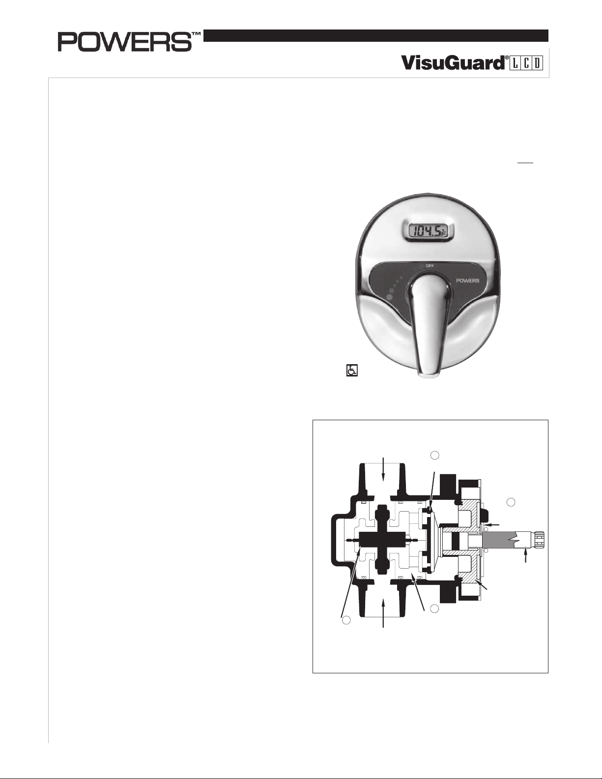
The maximum temperature stop (4) allows the user to set the
maximum discharge temperature. This mixer does not recognize supply water temperature changes, so any variation
in the water temperature will affect the control point and the
maximum temperature setting.
F473 shown
C473 Celsius
FIGURE 1 – OPERATION
Application n
The Visuguard LCD is particularly recommended in showers and shower bath installations for motels, hotels, dormitories, health care facilities, and single family residences.
Operation (SeeFigure 1) n
Hot and cold water enter their respective ports and the
flow of water is equalized through the action of the balance poppet (1). The entire balancing poppet assembly
is contained in a Celcon chamber (2). This chamber is
replaceable as a complete cartridge. After the hot and
cold flows are equalized, they are mixed by the action of
a mixing plate (3). As the temperature adjustment stem is
rotated from shutoff to maximum hot water temperature,
the mixing plate passes the required proportion of hot and
cold water to produce the control point. With the adjustment stem in its full clockwise position, shutoff is obtained
by closing both supplies.
NOTE: Following any maintenance of unit, maximum temperature stop must be reset. See page 4 for instructions.
Page 2
HOT
COLD
COLD
Outle t
Orientation o f Plate and Stem Assembly
for STANDARD Inlets
(Cold Water i nto Cold port)
Must Point
to CO LD Inlet
Notch in Hand le
Splin e
Must FACE TOP
Water
HOT
Water
C
Maintenance n
Troubleshooting
What to look for:
1. The flow of water is less than desired.
a. Valves upstream from supply not fully open.
b. Low supply pressures.
c. Accumulation of lime deposits in hot water pipes,
restricting the flow of hot water.
d. Showerhead clogged.
e. Checkstops may not be fully open.
f. Low hot water supply temperature.
2. Flow of water is completely shut off.
a. Valves upstream from supply completely closed.
b. Failure of hot or cold water supply pressure.
The Hydroguard is constructed to restrict the flow
of water on hot or cold water supply failure.
c. Checkstops closed.
3. Flow is untempered hot or cold water.
a. The water supplies are connected to the wrong ports.
Reconnect valve supplies to proper ports.
b. Diaphragm is ruptured; replace with new cartridge.
c. Check for foreign material that may be clogging the car-
tridge strainers.
4. Flow of water continues when VisuGuard LCD is shut off.
a. Worn shut-off discs. Replace worn disc.
b. Scratched mixing plate.
c. Erosion.ContactaPowersapplicationsengineerto
order replacement parts.
5. Maximum temperature is too low.
a. Accumulation of lime deposits in hot water pipes, which
restricts the flow of hot water.
b. The concealed maximum temperature limit stop is
not at its maximum adjustment. See page 5 to set the
maximum temperature limit stop.
c. Hot water temperature is too low.
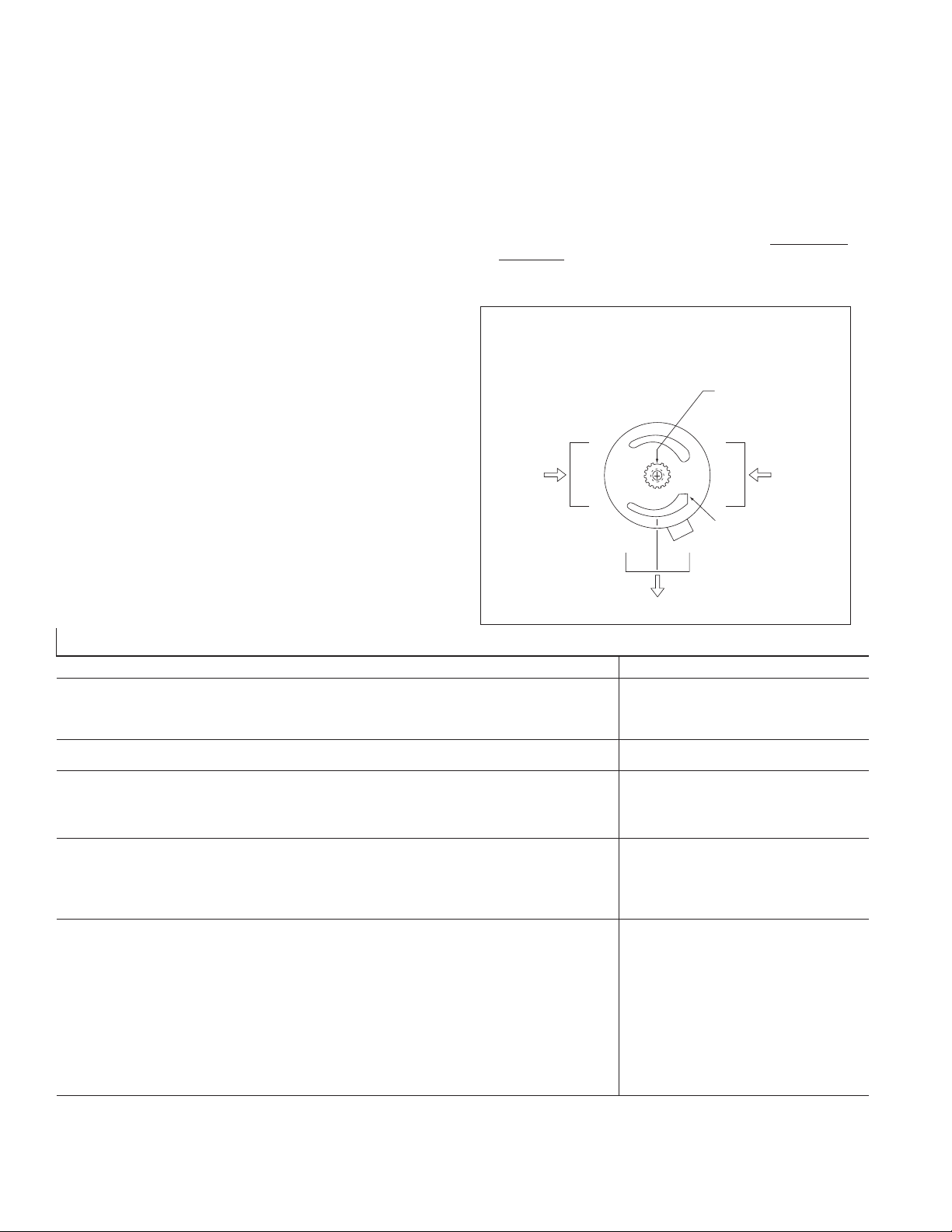
6. Standard inlets are desired.
See Figure 2 for instructions on standard inlets (with cold
water entering the COLD port). With mixer in closed position, the notch in the top spline on the stem must FACE
the outlet.
FIGURE 2 – STANDARD INLETS
Troubleshooting n
Description Recommended Repair Kit Kit Number and Contents
1. Water leaks at stem and/or bonnet.
2. Flow of water continues after mixer is turned off.
1. Variable or untempered discharge temperature. Balance Chamber 410-183 Items 8, 12, 13, 14, 15, 16, 17
1. Flow continues after mixer is turned off.
2. Handle splines on stem damaged.
1. Cartridge slips while seated in body.
2. Flow of water continues after mixer is turned off,
and all other seals have been replaced.
Electronics
1. Display not working (blank).
2. Temperature does not change on display when
handle is turned.
3. Temperature display does not respond rapidly
when handle is turned.
Notes:
1. Use silicone provided on all O-rings and related surfaces. Never use grease.
2. Some kits contain parts for all models; discard extra parts as appropriate.
Gasket and Disc
Replacement
Throttling Stem and Plate
Replacement
Oversize 410 Inlet
Seal Kit
Battery not properly installed
or "dead".
Temperature probe not
installed.
Temperature probe not
properly installed.
410-182 Items 3, 3A, 8, 12, 16
410-378 Items 3, 3A, 8, 9, 10, 11, 12
Discard Extra O-rings
410-570 Items 3, 3A, 8, 12, 16
Disgard oversized O-ring (not shown)
Replace or reinstall battery correctly.
Remove plate and install.(See Figure 7)
Reinstall (See Figure 7).
2
Page 3
1
2
3
4
5
6
7
8
9
3
10
11
18
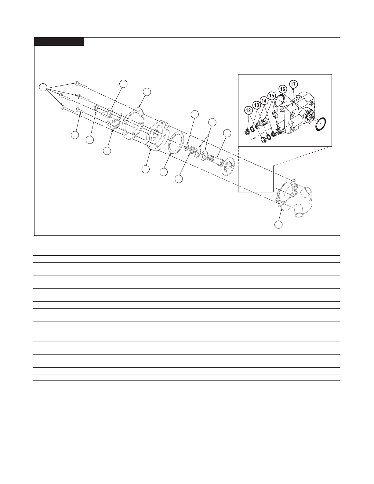
Parts n
Valve Assembly
Series 470 VisuGuard LCD Pressure equalizing mixer.
Poppet-type construction. Adjustable maximum temperature stop.
Item Part Description Kit/Part No. Quantity Material
1 Bonnet Screws (10-32 x 5/16") 030-885 4 Stainless Steel
2 Adjustment Stop Screw (10-32 x 5/16") 030-884 1 Stainless Steel
3 O-Rings (3/8" x 1/2" x 1/16") 047-020 4 Buna-N
4 Maximum Temperature Stop 401-218 1 Brass
5 Adjustment Stop 401-278 1 Stainless Steel
6 Support Ring 410-377 1 Stainless Steel
7 Bonnet 401-162 1 Noryl
8 Bonnet Gasket (Rainbow Style) 410-146* 1 Rubber
9 Wavy Washer 410-145* 1 Stainless Steel
10 Flat Washers 410-144 4 Synthane
11 Throttling Stem 410-375 – Brass Stem Celcon Plate
12 Shut-off Disc 400-023 1 Buna-N
13 O-Rings (2) 410-366 25 Buna-N
14 Guide 410-427 1 Brass
15 Spring 410-138 1 Monel
16 O-Ring 047-031 1 Buna-N
17 Cartridge 410-440 1 Celcon
18 Valve Body – 1 Brass
3
Page 4

29
28
27
26
25
24
23
22
21
19
20
30
31
Parts n
See laser etched ring to
determine valve model.
Series 473 VisuGuard LCD Pressure equalizing mixer.
Poppet-type construction. Adjustable maximum temperature stop.
Item Part Description Kit/Part No. Quantity Material
19 Nut, Ferrule, and 5/8” Sweat Plug 473-044 1 Brass & Copper
20 Probe Fitting N/A Brass
21 3 Port Mixer with Probe Fitting 473-033 1 Brass
22 Temperature Display with Probe 473-039 Various
23 Display Lens 473-041 1 Lexan
24 Gasket Display 473-041 1 Foam
25 Cover Plate 473-038 1 Chrome Plated Metal
26 Graphic Insert 473-043 1 Polycarbonate
27 Stem Gasket 473-045 1 Foam
28 Cover Plate Screws (Powder Coated) 473-042 10 Stainless
29 Handle & Set Screw 473-035 1 Chrome Plated Metal & Stainless
30 WindowPlateforNon-Electronic
Model N473 & N474
31 Set Screw 088-200 1 Stainless Steel
NLA 1 Chrome Plated Metal
VisuGuard LCD Kits
Kit/Part No. Description Includes:
473-035 Handle Kit Handle and Set Screw
473-037 StemExtensionKit StemExtension,(2)Longtrimplatescrews
473-038 Cover Plate Kit Cover Plate, Graphic Insert, Screws and Gaskets
473-039 Temperature Display Kit ElectronicDisplay(F/C),Housing,LensandGasket
473-041 Lens Kit Lens and Gasket
473-042 Coated Screw Kit (10) Powder Coated Screws
473-043 Graphic Insert Kit Graphic Insert
473-044 Installation Kit Cover Plate Gasket, Stem Gasket, Compression Nut,
473-045 Gasket Kit Cover Plate Gasket, Stem Gasket, and (2) Coated Screws
Ferrule, and Plug
4
Page 5

5/16’’ 1/16’’
Temperature
probe
Servicing n
1. Remove the dial assembly and handle. See page 3 for relationship of parts. Close checkstops or upstream valves.
Unscrew four bonnet assembly screws and remove bonnet
assembly by gently pulling on stem. Remove discs, O-rings,
seals, and springs from chamber.
2. TO REMOVE THE BALANCE CHAMBER, using a balance
chamber extraction tool (Part No. 401-202) is highly recommended. To use the extraction tool, follow instructions below:
a. Insert hooked ends of extraction tool into HOT
and COLD outlet ports of the balance chamber
(see Figure 4 below).
Figure 4 – BALANCE CHAMBER REMOVAL
Balance
Chamber
Extraction
Tool
b. Insert screwdriver down through end of extraction tool.
c. Place a wood or plastic block (do not use metal)
between screwdriver and valve body. Firmly ease
screwdriver away and downward,using wood for added
leverage ascartridge is gradually pulled out.
3. Replace necessary items and reassemble. Place a small
amount of silicone gel on the O-rings only.
4.
CAUTION: Do not pinch cartridge O-rings during assembly.
5. Replace bonnet with new bonnet gasket. Proceed to step 6
to reset maximum temperature setting.
Figure 5 – MAXIMUM TEMPERATURE SETTING
Maximum
Temperature
Stop
Adjustment Stem
Fin
Adjustment Stop
Adj. Stop Screw
Battery Replacement n
1. Remove Handle and Cover Plate.
2. Remove thermistor (temperature probe) by loosening small nut
on probe fitting (item 20).
3. Remove electronics enclosure (black) on back of cover plate
(attached with four screws).
4. Once enclosure is removed, carefully remove lens and electronic LCD display. Battery and battery holder are located on
back side of display.
5. Remove and replace battery (AAA alkaline).
6. Reverse procedure to reassemble.
Note: See Figure 7 for proper installation of temperature probe.
Figure 6
AAA Battery
Maximum Temperature Setting n
6. MAXIMUM TEMPERATURE SETTING (refer to Figure 5).
This must be set on the job and following any maintenance
or servicing to the valve. Mixer is factory set to pass full
HOT water.
Figure 7
a. Loosen adjustment stop screw (do not remove).
Gradually rotate stem counterclockwise to get desired
maximum water temperature. (Maximum Temperature
Stop will rotate along with the stem when the stem is
rotated.)
b. Once stem has been rotated to desired temperature,
slide adjustment stop clockwise until fin on adjustment
stop touches the maximum temperature stop.
c. While holding adjustment stop in place, tighten adjust-
ment stop screw.
d. Replace handle. Confirm maximum temperature has
been set properly by operating the valve using the handle.
CAUTION: Adjustment stop must be present for proper operation.
5
Page 6

Notes n
6
Page 7

Notes n
7
Page 8

Warranty n
The Seller warrants that the equipment manufactured by it and covered by this order or contract is free from defects in material and workmanship and, without
charge, equipment found to be defective in material or workmanship will be repaired, or at Seller’s option replaced F.O.B. original point of shipment, if written
notice of failure is received by Seller within one (1) year after date of shipment (unless specifically noted elsewhere), provided said equipment has been properly
installed, operated in accordance with the Seller’s instructions, and provided such defects are not due to abuse or decomposition by chemical or galvanic action.
THIS EXPRESS WARRANTY IS IN LIEU OF AND EXCLUDES ALL OTHER WARRANTIES, GUARANTEES, OR REPRESENTATIONS, EXPRESS OF IMPLIED. THERE ARE
NO IMPLIED WARRANTIES OF MERCHANTABILITY OR OF FITNESS FOR A PARTICULAR PURPOSE. The Seller assumes no responsibility for repairs made on the
Seller’s equipment unless done by the Seller’s authorized personnel, or by written authority from the Seller. The Seller makes no guarantee with respect to material
not manufactured by it.
A Watts Water Technologies Company
USA: Phone: 1.800.669.5430 • Fax 1.847. 229. 0526 • www.powerscontrols.com
Canada: Phone: 1.888.208.8927 • Fax 1.888. 479.2887 • www.powerscontrols.ca
IS-P-VISULCD1001 EDP#6511204 ©2010Powers
 Loading...