

Page 1
with HydroGuard
Technical Instructions
Description ■
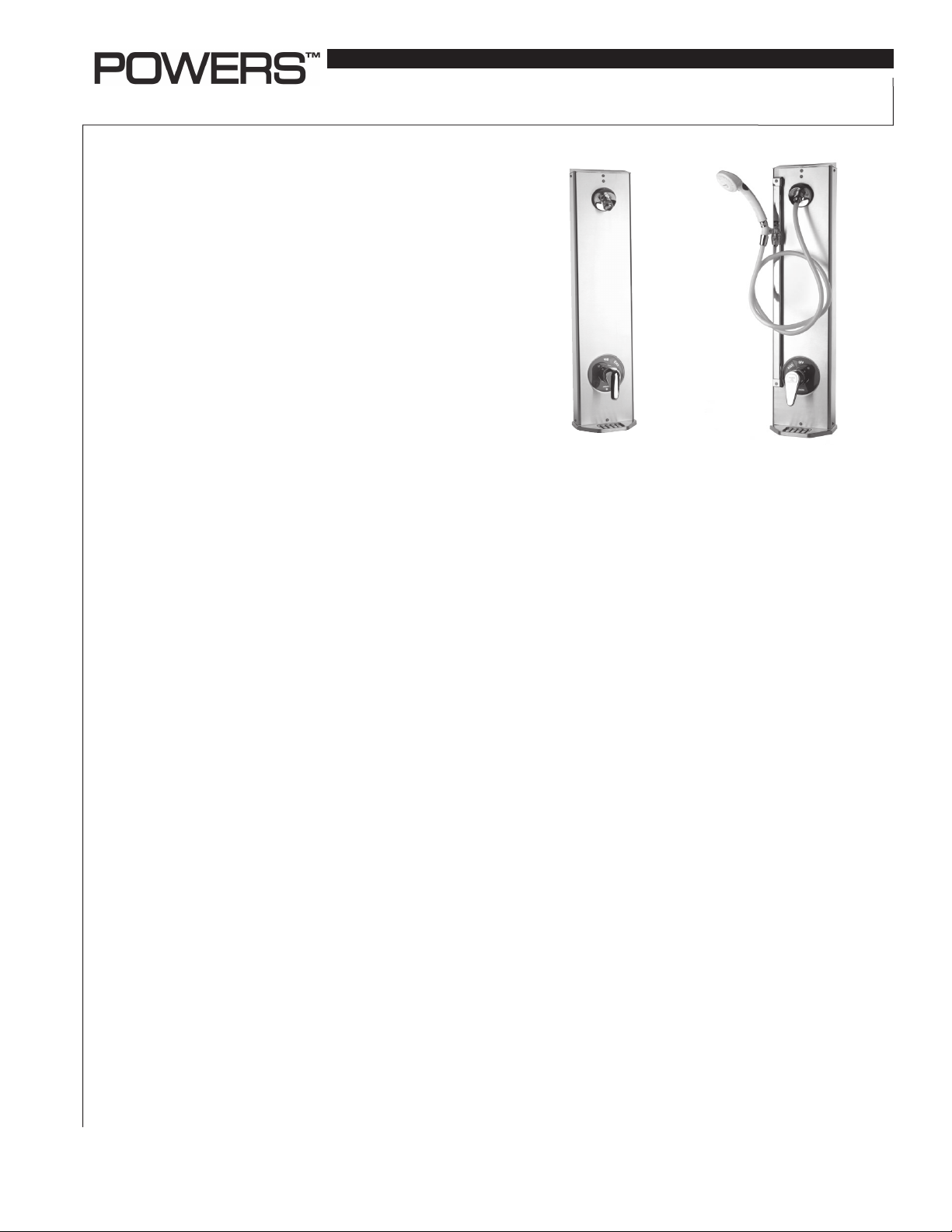
The Powers HydroPanel®II Shower System with HydroGuard®
T/P Series e700 valve combines water control with the convenience of modular shrouding. HydroPanel®II stainless steel
shrouding provides a concealed shower system where inwall piping does not exist or may not be practical.
The Series 450-7100 and 450-7050 HydroPanel®II comes complete with the stainless steel HydroPanel®II shrouding, Series
e700 valve with checkstops, piping, showerhead, end cap and
mounting hardware. Some models feature a stainless steel
soap dish. An optional hand shower comes pre-assembled
with a full spray push button hand shower, 60" hose, 18"
mounted glide-bar and connectors. The Series e700 valve is
CSA approved and ASSE type T/P listed.
The following instructions serve as guide for installation, general maintenance and parts replacement for HydroPanel®II
Shower Systems with e700 T/P combination Valves. For
detailed repair and maintenance instructions for the e700
valve or integral checkstops, please refer to Form ES-P-E700.
For specification or installation of the HydroPanel®II Modular
Shrouding for shower rooms, please refer to ES-P-450SH.
Operation ■
Hot and cold water enter respective ports in the valve and mix
in a chamber containing an advanced thermal actuator. This
actuator controls the position of the plunger and temperature.
Rotating the adjustment handle repositions the plunger in the
cartridge assembly to produce the desired temperature. The
mixed water passes over the shutoff disc to the outlet. If the
hot or cold supply water temperature or pressure changes,
the thermal actuator contracts or expands. This movement
repositions the plunger to maintain the desired temperature.
With the adjustment handle in full clockwise (OFF) position,
the shutoff disc closes the mixing chamber from the outlet.
A high temperature limit stop restricts the movement of the
control handle. All HydroGuard® T/P e700 valves are factory
set to deliver tempered water up to 110°F (43°C) with equal
supply pressures, with hot water temperature 140°F (60°C),
cold water temperature 60°F (15.6°C).
Features ■
• Installation requires minimal hardware: Mount the
brackets, connect supply piping and hang shrouding.
• All exposed surfaces are easy to clean stainless steel
or chrome plated.
• Fixed (vandal resistant) and swivel showerheads
are available.
• Single handle control and color coded dial offer quick
and easy temperature selection.
• Optional hand-held showers with flexible hoses mount
on 24" (610mm) glide rails for use in special applications.
IS-P-450-700
HydroPanel
®
T/P Series e700 Combination Valve
HydroPanel®II
Model 450-7100
• Optional HydroPanel
®
®
II Shower System
HydroPanel
Model 450-7054
®
II
II Modular Shrouding offers convenient
configuration of horizontal and vertical panels to cover all
exposed shower room piping. See ES-P-450SH for details
on HydroPanel®II Modular Shrouding.
• HydroGuard® T/P Series e700 are CSA certified and ASSE 1016
type T/P listed.
Specifi cations ■
HydroPanel®II : Brushed 18 Gauge 304 SS. Dimensions:
31-1/8" H x 7-1/2" W x 6" D (791 mm H x 191 mm x 154 mm D).
Piping: 1/2" (15mm) copper tubing.
Showerhead: Fixed: Chrome plated brass, maximum flow
2.5 gpm @ 80psi (0.16 l/s @ 552 kPa). Adjustable Swivel:
Chrome plated brass, 30° angle of rotation, maximum flow
2.5 gpm @ 80psi (0.16 l/s @ 552 kPa).
Valve Assembly and Trim: HydroGuard T/P Series e700
Combination Valve. Four port (bottom outlet plugged), cast brass
body with chrome plated zinc or ABS lever handle. 1/2" (15mm)
sweat inlet/outlet connections. Standard integral checkstops.
Metal to metal limit stop.
Valve Operation: 4.0 gpm @ 45psi differential
(15 l/min. @ 310 kPa). Maximum pressure (static)
125psi (862 kPa). Maximum inlet temperature 190°F (88°C).
Hand Shower: Full spray with pushbutton water control.
Minimum flow 2.0 gpm @ 20psi (0.13 l/s @ 138 kPa). Maximum
flow 2.5 gpm @ 80psi (0.16 l/s @ 138 kPa). 1/2" (15mm) chrome
finished supply connections. 24" (610 mm) chrome finished brass
glide bar, self-tensioned for easy height adjustment. Professional
model: 60" (1499 mm) reinforced vinyl hose. Deluxe Model:
60" (1499 mm) metal spiral hose.
Page 2

Installation ■
Before installation of any HydroPanel®II unit, rotate the stem
(or handle if attached) of the valve to its full clockwise position (OFF).
Position the HydroPanel
(See Figures 1 and 2) Determine the horizontal position of the unit
according to shower room layout, and mark the center line.
For multiple shower applications, the recommended minimum
distance between the center line of two units is 36" (1914 mm).
7-3/32"
(180)
®
II Unit
11/16"
(18)
1/2"
Copper Inlets
2-3/4"
(70
2-1/2"
(64
)
)
4-1/8"
(105
)
6. For mounting the piping assembly lower bracket (C),
drill one small holes in the wall 23-1/2" (587mm) below
the showerhead on the centerline.
7. Install any mounting anchors as detailed by the
individual room specifications.
8. Secure upper piping bracket B with mounting screws
(not included).
9. Secure lower piping bracket C with mounting screw
(not included).
2-1/4"
1-1/4"
(32)
1-3/4"
(44)
(57)
END CAP
A
B
1/2"
(13)
6"
)
FLOOR LINE
30"
21-1/4"
(762)
7/16"
(11)
(540)
(154)
6"
C for HydroPanel II™ unit
L
OFF
D
L
O
C
T
O
H
7-1/2"
(191)
Figure 1:
Front dimensions
HydroPanel®II
Model 450-7100
3-5/16"
(84)
For Suggested
Showerhead
Height see
General
Installation
(152)
4-3/4"
(121
Figure 2:
Side dimensions
HydroPanel®II
Model 450-7100
1. Determine the floor-to-showerhead height for the unit.
Recommended heights are listed below:
Men - 77" (1956 mm) Youth - 66" (1676 mm)
Women - 70" (1778 mm) Youth - 60" (1524 mm)
2. The pre assembled copper tubing supply water inlets are
4-1/8”(105 mm) from the top of the shroud, and 3-5/16"
(84mm) left and right of the center line. Adjust supply
piping accordingly.
Install the Piping Assembly
®
The valve handle assembly, piping and HydroPanel
II shrouding
must be separated before mounting to wall. For #450-7104, 7054,
7105, 7055, 7106 and 7056 HydroPanel®II units, the hand shower,
hose and showerhead base come pre-assembled to the shrouding. Refer to Figure 4.
3. Detach the valve assembly by removing valve retaining
screw, handle and collar. Undo the screws at D and take
off the dial insert.
4. Remove the screw at A above the showerhead. Slide the
piping out of the shrouding; the showerhead remains
attached to the shroud.
5. For mounting the piping assembly upper bracket (B), use the
bracket as a template and drill two small holes in the wall at
showerhead height.
24"
(610)
23-1/2"
(597)
D
OFF
D
L
O
C
T
O
H
4-3/4"
(121)
Figure 3:
D
Figure 4.
C
3-5/16"
(84)
Front dimensions
®
HydroPanel
II
Model 450-7104.
10. Connect the supply lines to the piping assembly.
Attach the Shrouding
Do not remove the entire chrome plated end cap from the
shrouding. It functions as an end cap and gasket for shroud
extension. Part of the end cap can be broken out to provide vertical and horizontal piping clearance.
11. To remove scored section, hit it sharply with a hammer.
12. To connect the showerhead on the shroud to the water outlet
pipe, slide the showerhead nipple on the inside of the shroud
into the piping assembly. The End Cap will slide over the
supply piping. Secure the shrouding with the screw at A.
Test the System
Before final assembly, test the HydroPanel®II system.
13. Fit the handle onto the valve stem and turn clockwise to the
shut off position.
14. Turn on water supply, and then rotate the valve handle counterclockwise. Water should come through the showerhead.
15. Now turn handle fully counterclockwise and measure the
temperature of the outlet water. Wait until the temperature
stabilizes for an accurate reading.
16. Turn off valve (fully clockwise) and check all connections
(showerhead, pipe connections, valve bonnet) for leaks.
2
Page 3

Installation Continued ■
Set the Limit Stop (See Figure 5)
The handle rotation setting must be adjusted to limit the
distance the user can rotate the handle towards the full
hot water position.
CAUTION: Any repair or modification of the valve will affect the
high temperature setting. Any changes in inlet water temperature
will require readjustment of the limit stop.
16. Remove the valve handle.
17. Adjust the valve to the desired maximum outlet
temperature (110°F (43°C) max). Screw on the high
temperature limit stop until it touches the stem shoulder.
18. Turn the stem clockwise until the water stops.
Open valve to full hot position and verify maximum
outlet temperature setting.
19. Replace handle. Repeat steps 17 through 18 until desired
maximum outlet temperature is reached. Remove handle
before final assembly of shrouding.
Assemble the Valve Cover and Handle
20. (Figure 4) Fit the dial insert onto the shrouding and secure
to the shroud and valve at D with the 2-1/4" screws.
21. Slide the O-ring and sleeve over the bonnet. Place the
lever over the stem, and secure with retaining screw
using Allen wrench.
22. (Figure 4) Finish assembly by tightening the shrouding
screw at A above the showerhead.
Servicing the HydroPanel®II Unit ■
Before servicing checkstops or piping, turn off the supply water
upstream. To access the checkstops, remove the valve handle
assembly, cover plate and shrouding (refer to Install the
Piping Assembly).
At least every twelve months, open up the checkstops and
check for free movement of the poppet.
Before servicing the valve, either turn off the water supply
upstream (the shroud does not have to be removed), OR access
and close the checkstops. To close the checkstops, turn the
adjustment screw on each fully clockwise.
Every twelve months, remove the valve bonnet and check the
internal components for freedom of movement.
To service or clean the showerhead, unscrew from shroud
at hex nut. Service as necessary, and reattach.
Troubleshooting ■
Note: For complete servicing the Series e700 Valves or Integral
checkstops, please refer to Technical Instructions Form TI e700.
What to look for if:
The maximum temperature cannot be obtained...
a. Lime deposits may have accumulated in the hot water
pipes, restricting the hot water supply.
b. The hot water supply temperature may be too low.
c. The handle rotation setting may be too low. Remove valve
handle, and readjust the high temperature limit stop.
Figure 5.
STEM
HIGH TEMP. LIMIT STOP
Flow of water is less than desired…
a. The upstream supply valves may not be fully open.
b. The inlet supply pressure(s) may be low.
c. The showerhead may be clogged. Remove and clean
the showerhead.
d. The checkstops may be clogged.
The valve opens with hot water fl ow rather than
cold water fl ow...
a. The inlet water supplies are connected to the wrong
ports or cartridge is installed improperly.
The tempered water is too cold, although cartridge has been
replaced, OR the hot water temperature is below 115°F...
a. Raise the temperature of the hot water supply.
Flow of water is completely shut off...
a. The upstream supply valves may be completely closed.
b. The hot or cold water supply pressure may have failed.
The e700 valve is designed to close down upon cold
water supply pressure failure.
c. The checkstops may be closed. Access the checkstops
and open by turning the adjustment screw fully
counterclockwise.
3
Page 4

Part List ■ Ordering information ■
# Part # Description Qty Material
1 N/A Shroud 1 St Steel
2 450 268 Soap Dish 1 St Steel
3 4504011 End Cap Kit 1 Chrm Plt ABS
4 450 273 Screw 10-32 x 3/8 (shrouding) 7 St Steel
5 450 276 Set Screw 10-32 x 7/8 1 St Steel
6 141 816 Fixed Showerhead 1 Chrm Plt Brass
7 141 379 Swivel Showerhead 1 Chrm Plt Brass
8 450 277 Gasket, Showerhead Base 1 Garlock 3000
9 450267G Showerhead Base 1 Chrm Plt Brass
10 047 013 Quad Ring 3/8 x 1/2 x 1/16 1 Buna N
11 450 274 Screw 10-32 x 1/4 (showerhead) 3 Brass
12 220 050 Metal Handle Kit 1 St Steel
13 220 052 ABS Handle Kit 1 Chrm Plt Zinc
14 220 054 Sleeve Kit 1 Chrm Plt Brass
15 450 272 Screw 8-32 x 2-1/4 (dial insert) 2 St Steel
16 450 270 Insert Dial 1 Al w/Mylar
17 N/A HydroGuard® /Piping Assembly 1 —
NS 089 003 3/32” Service Wrench 1 Steel
NS 089 004 1/8” Service Wrench 1 Steel
NS 220 060 Cartridge Kit 1 —
NS 900 050 Check Stop Replacement Kit 1 —
NS = Not shown in diagram NA = Not available
3
4
10
9
8
7
6
5
16
15
14
13
12
11
17
1
4
HydroPanel®II with HydroGuard®T/P e710
Combination Mixing Valves with ABS Handles Order Code
Fixed Showerhead and Soap Dish ......................................... 450-7050
Fixed Showerhead less Soap Dish ......................................... 450-7051
Swivel Showerhead with Soap Dish ...................................... 450-7052
Swivel Showerhead less Soap Dish ...................................... 450-7053
Professional Hand Shower, Glide Rail, VB
and Soap Dish* ............................................................................ 450-7054
Professional Hand Shower, Glide Rail, VB
less Soap Dish* ............................................................................ 450-7055
Deluxe Hand Shower, Glide Rail, VB
and Soap Dish* ............................................................................ 450-7056
Deluxe Hand Shower, Glide Rail, VB
less Soap Dish* ............................................................................ 450-7057
Professional Hand Shower, Glide Rail, VB,
Fixed Showerhead & Soap Dish* ............................................ 450-7058
Professional Hand Shower, Glide Rail, VB,
Swivel Showerhead & Soap Dish*.......................................... 450-7059
HydroPanel
®
II with HydroGuard®T/P e710 Combination
Mixing Valves with Metal Handles
Fixed Showerhead and Soap Dish ......................................... 450-7100
Fixed Showerhead less Soap Dish ......................................... 450-7101
Swivel Showerhead with Soap Dish ...................................... 450-7102
Swivel Showerhead less Soap Dish ...................................... 450-7103
Professional Hand Shower, Glide Rail, VB
and Soap Dish* ............................................................................ 450-7104
Professional Hand Shower, Glide Rail, VB
less Soap Dish* ............................................................................ 450-7105
Deluxe Hand Shower, Glide Rail, VB
and Soap Dish* ............................................................................ 450-7106
Deluxe Hand Shower, Glide Rail, VB
less Soap Dish* ............................................................................ 450-7107
Professional Hand Shower, Glide Rail, VB,
Fixed Showerhead & Soap Dish* ............................................ 450-7108
Professional Hand Shower, Glide Rail, VB,
Swivel Showerhead & Soap Dish*.......................................... 450-7109
* ADA Compliant
2
3
ENGINEERING APPROVAL
Project:
Contractor:
Warranty ■
The Seller warrants that the equipment manufactured by it and covered by this order or contract is free from defects in material and workmanship and, without
charge, equipment found to be defective in material or workmanship will be repaired, or at Seller’s option replaced F.O.B. original point of shipment, if written
notice of failure is received by Seller within one (1) year after date of shipment (unless specifically noted elsewhere), provided said equipment has been properly
installed, operated in accordance with the Seller’s instructions, and provided such defects are not due to abuse or decomposition by chemical or galvanic action.
THIS EXPRESS WARRANTY IS IN LIEU OF AND EXCLUDES ALL OTHER WARRANTIES, GUARANTEES, OR REPRESENTATIONS, EXPRESS OF IMPLIED. THERE ARE
NO IMPLIED WARRANTIES OF MERCHANTABILITY OR OF FITNESS FOR A PARTICULAR PURPOSE. The Seller assumes no responsibility for repairs made on the
Seller’s equipment unless done by the Seller’s authorized personnel, or by written authority from the Seller. The Seller makes no guarantee with respect to material
not manufactured by it.
USA: Phone: 1.800.669.5430 • Fax 1.847. 229. 0526 • www.powerscontrols.com
Canada: Phone: 1.888.208.8927 • Fax 1.888.479.2887
Architect/Engineer:
• www.powerscontrols.ca
IS-P-450-700 0826 EDP# 6512258 © 2008 Powers
 Loading...