

Page 1
HydroPanel™ II Shower System
with HydroGuard® e420 Combination Valve
Technical Instructions
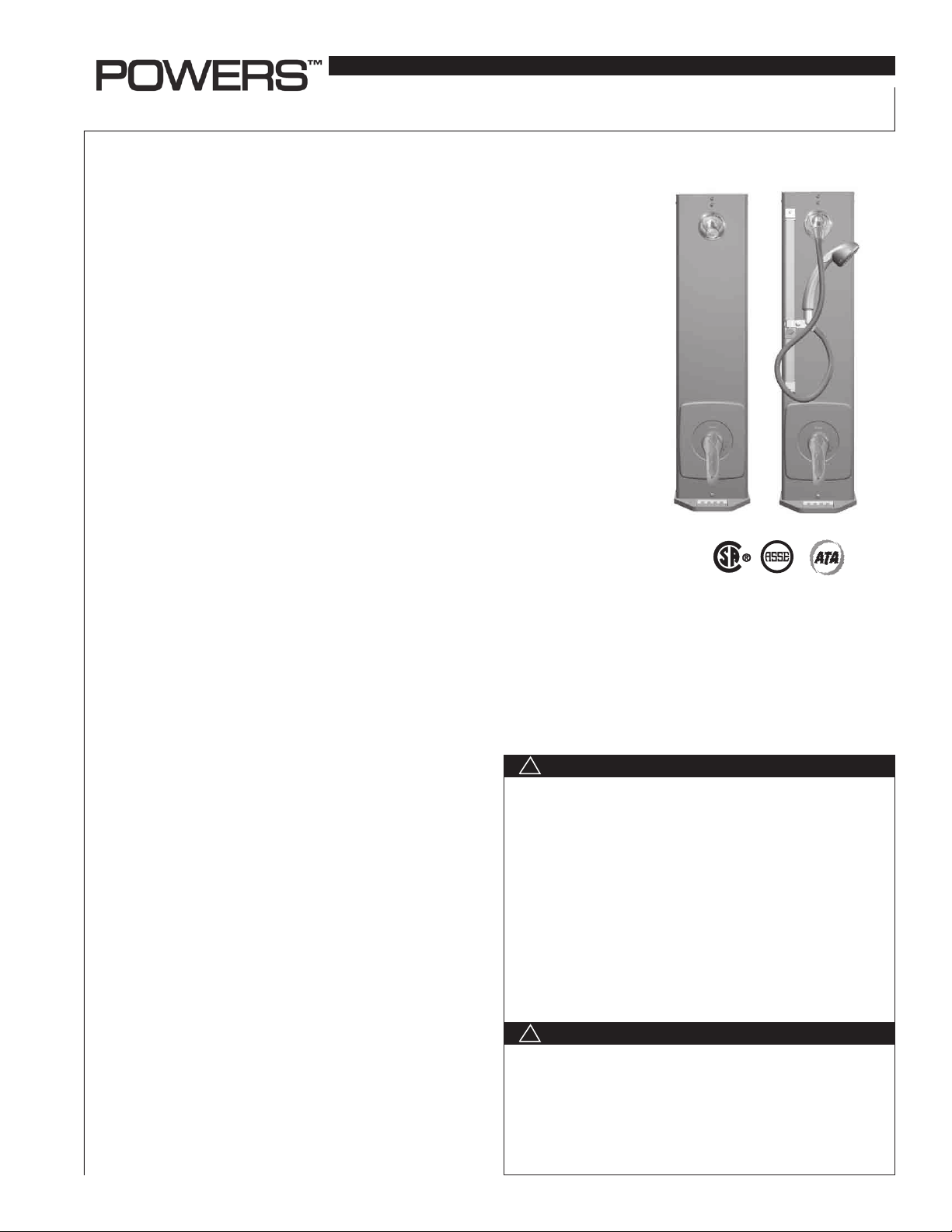
Description n
The Powers HydroPanel™ II Shower System with HydroGuard® e420 valve combines
thermostatic and pressure balancing water control with the convenience of modular
shrouding. It provides a concealed shower system where in-wall piping does not exist
or may not be practical. The HydroGuard® e420 features heavy cast brass construction,
self actuated thermostatic element to quickly sense any change in hot or cold supply
water temperature or pressure and respond to maintain the user selected temperature.
In the event of cold water failure, the thermostatic element virtually shuts off the flow of
hot water. A built-in adjustable metal-to-metal temperature limit stop reduces chances
of accidental scalding due to over adjustment of handle. HydroPanel™ II comes complete
with inline checkstops, stainless steel shrouding, e420 combination valve, ADA compliant
lever handle, piping, end caps and mounting hardware. Some models feature a stainless
steel soap dish. An optional hand shower comes preassembled.
Specifications n
HydroPanel™ . . . . . . . . . . . . . . . . . . . . . . . . . . . . . Brushed 18 Gauge 304 stainless steel
Piping . . . . . . . . . . . . . . . . . . . . . . . . . . . . . . . . . . . 1/2" (15mm) copper tubing
Connections . . . . . . . . . . . . . . . . . . . . . . . . . . . . . . 1/2" (15mm) copper
Flow Rate . . . . . . . . . . . . . . . . . . . . . . . . . . . . . . . . 5 gpm (19 lpm) +/- 0.25 gpm [0.90 lpm]
Maximum Hot Water Temperature . . . . . . . . . . 190°F (88°C)
Minimum Hot Water Temperature* . . . . . . . . . . 10°F (6°C) Above Set Point
Maximum Operating Pressure . . . . . . . . . . . . . . 125psi (862 kPa)
Showerhead . . . . . . . . . . . . . . . . . . . . . . . . . . . . . Fixed chrome plated brass
Adjustable swivel chrome plated brass
Hand Shower . . . . . . . . . . . . . . . . . . . . . . . . . . . . . Full spray with push button
Listing/Certification (Valve only) . . . . . . . . . . . . ASSE 1016, CSA B125
*with equal pressure
!
WARNING
FAILURE TO COMPLY WITH PROPER INSTALLATION AND
MAINTENANCE INSTRUCTIONS COULD CONTRIBUTE
TO THE VALVE FAILURE, RESULTING IN INJURY AND/OR
DEATH.
TO ENSURE THE ACCURATE AND RELIABLE OPERATION
OF THIS PRODUCT, IT IS ESSENTIAL TO:
• Properly design the system to minimize pressure and temperature variations.
• Conduct an annual maintenance program to ensure proper
operation of all critical components.
• Check outlet temperature to ensure it does not exceed
110°F (43°C). Make sure temperature limit stop is properly reset to maximum 110°F (43°C) following valve maintenance or
repair. Tampering with limit stop in any way may result in scalding temperature causing serious bodily harm
!
WARNING
Need for Periodic Inspection: Periodic inspection by a
licensed contractor is recommended. Corrosive water conditions, and/or unauthorized adjustments or repair could render
the valve ineffective for service intended. Regular checking
and cleaning of the valve’s internal components and check
stops helps assure maximum life and proper product function. Frequency of cleaning and inspection depends upon
local water conditions.
IS-P-450_e420
Advanced Thermal Activation
and/or death.
Page 2
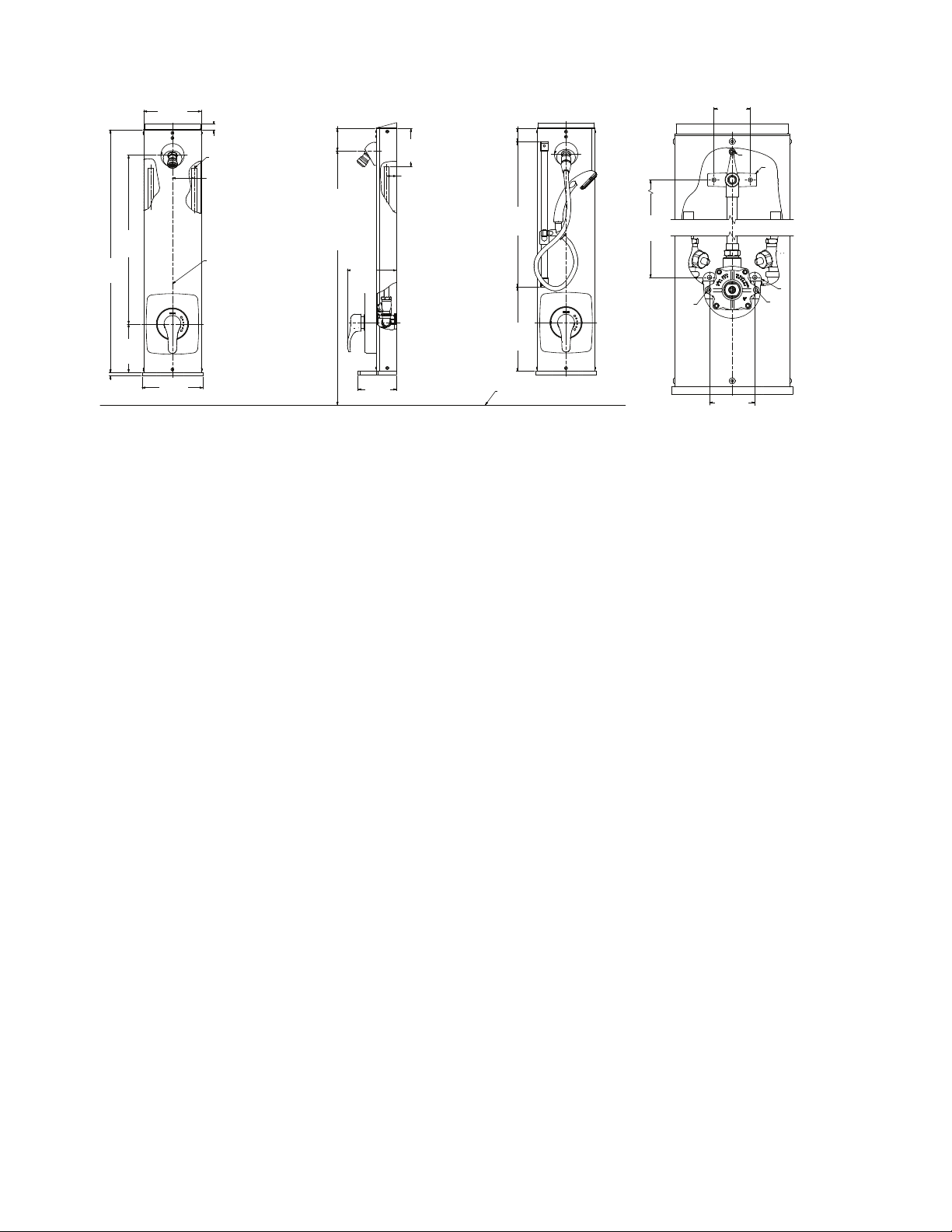
Installation n
3
7 3/32
[180]
/4"
3/4
(18)
[18]
1
/2" COPPER
PER
1/2" COP
INLETS
INLETS
2 11/16
2 11/16"
[68]
(68)
2 3/4"
2 3/4
[70]
(70)
FOR SUGGEST-
4 3/4"
4 3/4
[120]
(120)
1 1/4"
1 1/4
[32]
(32)
7 3/32"
(180)
ED SHOWER-
HEAD HEIGHT
FOR SUGGES TED
SHOWERHEAD
SEE GENERAL
20 7/8"
20 7/8
[530]
(530)
30
30"
[762]
(762)
6"
6
[152]
(152)
7
7/16
/16"
[11]
(11)
Figure 1: Front dimensions,
HydroPanel II Model 450-4210E
7 1/2"
(191)
Figure 1: F ront dimension s,
Hydropanel II Model 450-4210E
7 1/2
[191]
CENTERLINE FOR
CENTERL NE FOR
HYDROPANEL U NIT
I
HYDROPANEL
UNIT
HEIGHT SEE
GENERAL INS TALLATION
INSTALLATION
6 1/16"
6 1/16
[154]
(154)
4 3/4"
4 3/4
[121]
(121)
Figure 2: Side dimensions,
Figure 2: Si de dimensions ,
HydroPanel II Model 450-4210E
Hydropanel II Model 450-4210E
Installation should be in accordance with acceptable plumbing
practices. Flush all piping thoroughly before installation.
Failure to do so can result in valve malfunction. Before installation
of HydroPanel™ II, rotate the stem or handle off.
Position The HydroPanel™ II Unit n
1. See Figure 1, 2 & 3 to determine the horizontal position of the
unit according to shower room layout and mark the centerlines. For multiple shower applications, the recommended
minimum distance between the centerlines of the two units is
36 inches (914 mm).
2. Determine floor to showerhead height for the unit.
Recommended heights--for men 77" (1956 mm), male youth 66"
(1676 mm), women 70" (1778 mm) and female youth 60" (1524
mm).
3. The preassembled copper tubing for supply water inlets are
4-3/4" (120 mm) from the top of the shroud and 2-11/16" (68 mm)
left and right of the centerline. Adjust supply line accordingly.
Install the Piping Assembly n
1. Detach the piping from the shrouding by removing screw A
above the showerhead (see Figure 4). Slide piping out of the
shrouding; the showerhead remains attached to the shroud.
2. For mounting the piping assembly bracket B, use bracket as
a template and drill 2 small holes in the wall at showerhead
height.
3. For mounting lower piping assembly, drill a small hole in the
wall that is 20-1/2" (520 mm) below the upper bracket (B) and
1-13/32" (36 mm) to the left and right of the center line.
4. Install mounting anchors per room specifications. Secure
bracket with mounting screws (NOT INCLUDED).
5. Connect the supply lines to the piping assembly.
2 1/4"
1 9/16"
1 9/16
(40)
[40]
18
18"
[457]
(457)
10 3/8
10 3/8"
[264]
(264)
FLOOR LINE
FLOOR LINE
Figure 3: Front dimensions,
Figure 3: Fro nt dimensions,
HydroPanel II Model 450-4214E
Hydropanel II Model 450-4214E
20 1/2"
20 1/2
[520]
(520)
2 1/4
(57)
[57]
END CAP
A
B
HOT COLD
D
2 13/16
2 13/16"
[71]
(71)
Figure 4.
Fig. 4
C
D'
Attach the Shrouding n
Do not remove the entire chrome plated end cap from the
shrouding; it functions as an end cap and gasket for shroud
extension. Part of the end cap can be broken out to provide vertical and horizontal piping clearance.
1. To remove scored section, hit it sharply with a hammer.
2. To connect the showerhead, slide the showerhead nipple
on the inside of the shroud into the piping assembly. Secure
shrouding with the screw at A.
3. Fit the handle over the stem. Turn on water supply. Turn
handle fully counterclockwise and measure the outlet water
temperature. Adjust temperature if required (see high temperature limit stop adjustment)
4. Check for leaks. Secure shrouding.
5. The cover plate fits over the tabs around the shroud valve
hole. Snap the cover plate into place. Secure it at D and D'
with screws.
6. Place the name plate over the cover plate, snap the retaining
ring. Thread sleeve on the bonnet making sure that the cut-away on the sleeve is toward you, and it is in the bottom position when tightened.
7. Install the handle with the screw provided.
2
Page 3

High Temperature Limit Stop Adjustment n
Maximum temperature setting adjustment must be set on job site
(See Fig. 5). The high temperature limit stop is threaded into the
bonnet and is turned counterclockwise for an increased setting
and clockwise for a decreased setting. Powers recommends a
maximum setting of 110°F (43°C). To adjust temperature, rotate
handle to the maximum desired outlet temperature, screw temperature limit stop until it touches stem's shoulder. Close valve
and open it to verify setting.
Figure 5
MAXIMUM
TEMPERATURE
LIMIT STOP
WARNING
Always verify the maximum tempera-
!
ture setting to the valve after any
changes are made. This should also be
checked as a part of a facilities maintenance/
safety program.
Troubleshooting n
What to look for if:
1. The flow of the water is less then desired.
a. Valves upstream from supply not fully open.
b. Low supply pressure.
c. Accumulation of lime deposit in hot water pipes, restricting
the flow of the hot water
d. Showerhead clogged. Remove and clean.
e. Checkstops may not be fully open.
2. Flow of water is completely shut off.
a. Valves upstream from supply completely closed.
b. Failure of hot or cold water supply pressure.
c. Checkstops closed.
3. If the water varies in temperature.
a. Lime deposit may have accumulated in the hot water
pipes, restricting water flow.
b. Thermostatic wax element may have failed. Replace wax
element.
c. The inlet water supplies may be connected to the wrong
ports. Remove HydroPanel™ II and re-install.
d. There may be extreme pressure variation in the water sup-
ply lines. Check with plumber or plumbing engineer.
4. Flow of water continues when valve is shut off.
a. Worn shutoff disc. Replace cartridge.
5. Checkstops leak or they won't shut off.
a. The checkstops may be damaged. Replace with check-
stop replacement kit.
6. Maximum temperature is too low.
a. Accumulation of lime deposit in hot water pipes, restricting
the flow of the hot water.
b. The concealed maximum temperature limit stop is not at
its maximum adjustment. Set the maximum temperature
limit stop.
c. Hot water temperature is too low.
Servicing n
Before servicing checkstops or piping, turn off water supplies
upstream. To access the checkstops, remove handle, name
plate and cover plate.
At least every twelve months, open up the checkstops and
check for the free movement of the poppet.
Before servicing the valve, either turn off the water supply
upstream or close the checkstops. To close the checkstops,
turn the adjustment screw on each stops clockwise.
Every six month, check and adjust the handle rotation setting.
Every twelve months, remove the valve bonnet and check the
internal components for the freedom of movement.
3
Page 4

The Seller warrants that the equipment manufactured by it and covered by this order or contract is free from defects in material and workmanship and, without
charge, equipment found to be defective in material or workmanship will be repaired, or at Seller’s option replaced F.O.B. original point of shipment, if written
notice of failure is received by Seller within one (1) year after date of shipment (unless specifically noted elsewhere), provided said equipment has been properly
installed, operated in accordance with the Seller’s instructions, and provided such defects are not due to abuse or decomposition by chemical or galvanic action.
IMPLIED. THERE ARE
The Seller assumes no responsibility for repairs made on the
Seller’s equipment unless done by the Seller’s authorized personnel, or by written authority from the Seller. The Seller makes no guarantee with respect to material
Parts List n
Parts List
Item Part Number Description
1 N/A SHROUD (showerhead)
1 N/A SHROUD (handshower)
2 450273A SCREW 10-32 UNF x 1/4
3 450 268 SOAP DISH
4 450269G CAP, END CHROME PLATE
5 450 356 COVER PLATE
6 420 049 HANDLE KIT
7 420 017 SLEEVE
8 227 167 RETAINER - DIAL INSERT
9 420 063
10 080 009 SCREW 8-32 X 1-1/4
11 141 379
12 141 816 SHOWERHEAD - FIXED
13 141 837
14 141 319
15 042672G NIPPLE - 12" 'NPT X 1-1/8" LG
16 450 277 GASKET - SHOWERHEAD BASE
17 450 276 SET SCREW 10-32 UNF X 7/8
18 450267G
19 047 013 QUAD RING 3/8" ID X 1/2" OD
20* 420 452 KIT, CARTRIDGE
21* 420 024 WAX ELEMENT
22* 420 457 KIT, BONNET
23* 141 000 KIT, CHECKSTOP
NAMEPLATE & BA SE P L A T E
ASSEMBLY
SHOWERHEAD - A DJUSTABLE
SWIVEL
PUSHBUTTON SHOWER HAND
SPRAY
IN-LIN E VA C UUM BREAKE R
(handshower)
(handshower)
BASE, SHOWERHEAD CHROME
PLATE
4
2
19
18
17
16
15
14
13
12
11
10
9
8
7
6
5
2
1
2
3
4
* Not Shown
NOTE: AFTER COMPLETING REPAIRS,
CHECK DISCHARGE TEMPERATURE.
!
RESET IF NECESSARY.
WARNING: FAILURE TO PERFORM THIS
OPERATION COULD RESULT IN UNSAFE
DISCHARGE TEMPERATURE, WHICH MAY
CAUSE INJURY OR DEATH.
Warranty n
THIS EXPRESS WARRANTY IS IN LIEU OF AND EXCLUDES ALL OTHER WARRANTIES, GUARANTEES, OR REPRESENTATIONS, EXPRESS OF
NO IMPLIED WARRANTIES OF MERCHANTABILITY OR OF FITNESS FOR A PARTICULAR PURPOSE.
not manufactured by it.
A Watts Water Techn ologies Company
IS-P-450_e420 1045 EDP# 6511211 © 2010 Powers
USA: Phone: 1.800.669.5430 • Fax 1.847. 229. 0526 • www.powerscontrols.com
Canada: Phone: 1.888.208.8927 • Fax 1.888. 479.2887 • www.powerscontrols.ca
 Loading...