

Page 1
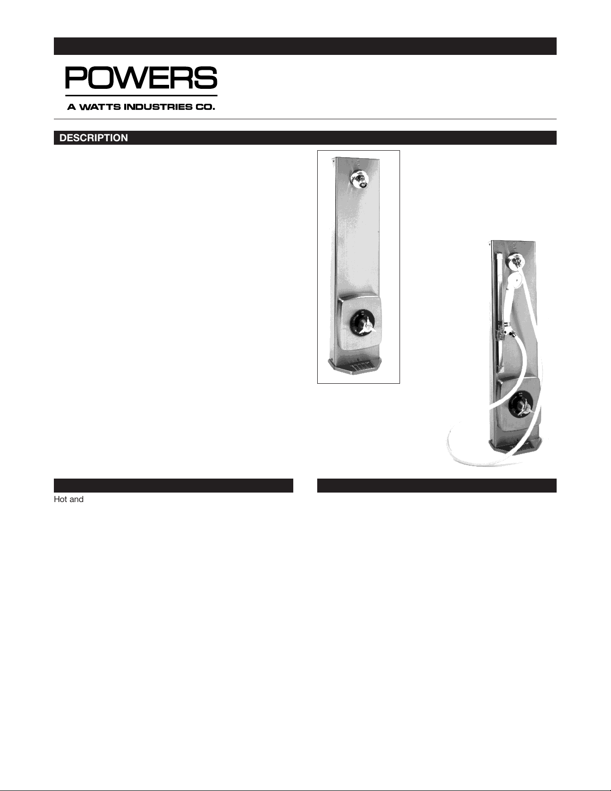
The Powers Hydropanel II Series 450-4200 Shower System combines thermostatic water control with the convenience of modular shrouding. Hydropanel II stainless steel shrouding provides a
concealed shower system where in-wall piping does not exist or
may not be practical. The Hydroguard 420 valve uses a self-actuated thermostatic motor to quickly sense any change in hot or
cold supply water temperature or pressure and respond to maintain the user-selected temperature. In the event of cold water failure, the thermostatic motor virtually shuts off the flow of hot
water. The unit also features a concealed handle rotation stop to
guard against over adjustment of the handle.
The Series 450-4200 Hydropanel II comes complete with the
stainless steel Hydropanel II Shrouding, Series 420 Hydroguard,
in-line checkstops, piping, showerhead, end cap and mounting
hardware. Some models feature a stainless steel soapdish. Some
models feature an ADA compliant lever handle. An optional
handshower comes preassembled with a full spray pushbutton
handshower, 60” hose, 18” mounted glide-bar and connectors.
The Hydroguard 420 valve is CSA approved, and the Series 4504200 Hydropanel II carries a one-year limited warranty.
The following instructions serve as guide for installation, general
maintenance and parts replacement for the Hydropanel II Series
450-4200. For detailed repair and maintenance instructions for
the Hydroguard 420 valve, please refer to Form #TI420-1. For
repair and maintenance of checkstops, see Form #129-028. For
specification or installation of the Hydropanel II Optional Modular
Shrouding for shower rooms, please refer to Forms #PS450SH or
#TI450SH.
TECHNICAL INSTRUCTIONS
HYDROPANELTMII SHOWER SYSTEM
with Hydroguard 420 Thermostatic Valve
A Watts Industries Co.
DESCRIPTION
Hot and cold water enter respective ports in the valve and mix in
a chamber containing a thermostatic motor. This liquid filled
motor connects to the valve assembly, which includes a hot
water seat and a shut off disc. With the adjustment handle in full
clockwise (OFF) position, the shut-off disk closes the mixing
chamber from the outlet, and the hot water disc seats to prevent
crossflow.
Rotating the adjustment handle repositions the valve assembly to
mix hot and cold supply water in proportions required to produce
the user-selected temperature. The mixed water passes over the
shut-off disc, to the showerhead. If the mixed water temperature
differs from the handle setting (i.e., the hot or cold supply water
temperature or pressure changes) the liquid filled bellows inside
the thermostatic motor will contract or expand. This movement
repositions the valve assembly to maintain the desired delivery
temperature.
A handle rotation stop limits the movement of the control handle
toward the full hot position. The Hydroguard 420 valve is factory
set to deliver tempered water up to 115°F [46.1°C] with equal
supply pressures, hot water temperature 140°F [60°C], cold water
temperature 60°F [15.6°C].
OPERATION
Hydropanel: Brushed 18 Gauge 304 SS. Dimensions 311⁄8”H x
71⁄2”W x 61⁄2”D [791mm H x 191mm W x 165mm D].
Piping: 1/2” copper tubing.
Showerhead: Fixed: Chrome plated brass, maximum flow 2.5
gpm @ 80 psi [.16 l/s @ 552 kPa]. Adjustable Swivel: Chrome
plated brass, 30° angle of rotation, maximum flow 2.5 gpm @ 80
psi [.16 l/s @ 552 kPa].
Valve Assembly and Trim: Hydroguard 420 Thermostatic Mixing
Valve. Three port, heavy cast bronze body with brass stem.
Standard in line checkstops. Concealed handle rotation
stop.Chrome plated zinc tri-handle, or ADA compliant lever handle.
Connections: 1/2” NPT inlets and outlet.
Valve Operation: 6 gpm @ 45 psi differential [.38 l/s @ 310 kPa].
Maximum pressure 125 psig [862 kPa]. Maximum inlet temperature 190°F [88°C].
Handshower: Full spray with pushbutton water control. Minimum
flow 2.0 gpm @ 20 psi [.13 l/s @ 138 kPa]. Maximum flow 2.5
gpm @ 80 psi [.16 l/s @ 138 kPa]. 60” [1499mm] reinforced vinyl
hose with 1/2” chrome finished supply connections. 18” [457mm]
chrome finished brass glide bar, self-tensioned for easy height
adjustment.
SPECIFICATIONS
Hydropanel II Model 450-4202
with Swivel Showerhead and
Soapdish (available with ADA
compliant lever handle, Model
450-4212).
Hydropanel II Model 450-4204
with Handshower Assembly and
Soapdish (available with ADA
compliant lever handle Model
420-4214).
Form TI450-420
Page 2
TI450-420 Page 2
Before installation of any Hydropanel II unit, rotate the stem (or
handle if attached) of the valve to its full clockwise position (OFF).
POSITION THE HYDROPANEL II UNIT
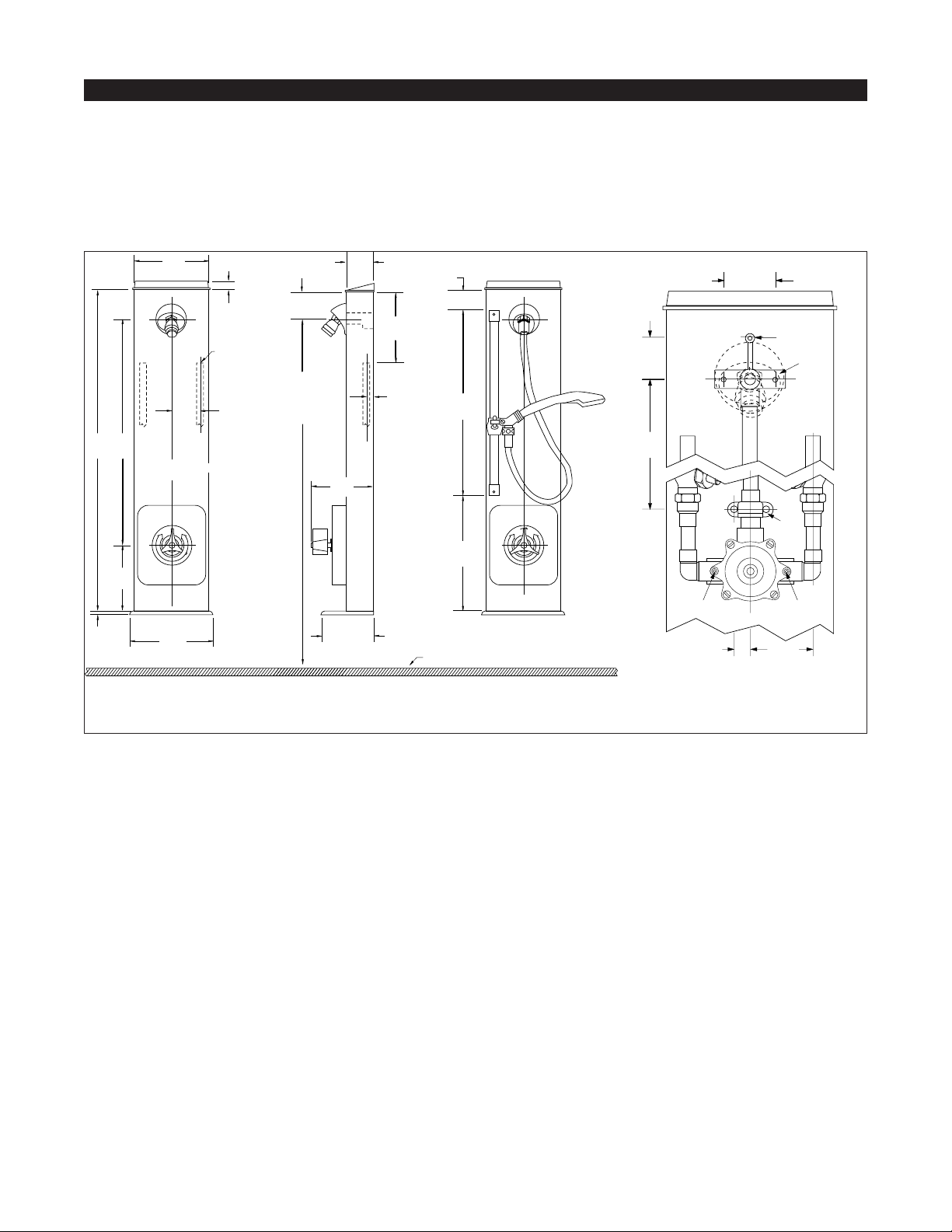
(See Figures 1 and 2) Determine the horizontal position of the unit
according to shower room layout, and mark the centerline. For
multiple shower applications, the recommended minimum distance between the centerline of two units is 36 inches [1914mm].
1. Determine the floor-to-showerhead height for the unit.
Recommended heights are listed below:
Men - 77” [1956mm] Youth - 66” [1676mm]
Women - 70” [1778mm] Youth - 60” [1524mm]
2. The preassembled copper tubing for supply water inlets are
6-5/8” [168mm] from the top of the shroud and 2-11/16”
[68mm] left and right of the centerline. Adjust supply piping
accordingly.
Install the Piping Assembly
The piping and Hydropanel II shrouding must be separated
before mounting to wall. The valve trim and cover plate are in a
separate plastic bag in the Hydropanel II shipping carton. For
#450-4204 and #450-4205 Hydropanel II units, the hand-shower,
hose and showerhead base come preassembled to the shrouding. Refer to Figure 4.
3. Detach the piping from the shrouding, by removing screw A
above the showerhead. Slide piping out of the shrouding;
the shower head remains attached to the shroud.
4. For mounting the piping assembly upper bracket (B), use
the bracket as a template and drill two small holes in the wall
at showerhead height.
5. For mounting the piping assembly lower bracket (C), drill two
small holes in the wall that are 18-3/4” [476mm] below the
upper bracket, and 11/16” [17mm] to the left and right of
centerline.
6. Install any mounting anchors as detailed by the individual
room specifications.
7. Secure upper piping bracket B with mounting screws (not
included).
8. Secure lower piping bracket C with mounting screws (not
included).
9. Connect the supply lines to the piping assembly.
Attach the Shrouding
Do Not remove the entire chrome plated end cap from the
shrouding; it functions as an end cap and gasket for shroud
extension. Part of the end cap can be broken out to provide vertical and horizontal piping clearance.
10.To remove scored section, hit it sharply with a hammer.
11.To connect the showerhead on the shroud to the water outlet pipe, slide the showerhead nipple on the inside of the
shroud into the piping assembly. The End Cap will slide over
the supply piping. Secure the shrouding with the screw at A.
Test the System
Before final assembly, test the Hydropanel II system.
12.Fit the handle onto the valve stem and turn clockwise to the
shut off position.
13.Turn on water supply, and then rotate the valve handle counterclockwise. Water should come through the showerhead.
14.Now turn handle fully counterclockwise and measure the
temperature of the outlet water. Wait until the temperature
stabilizes for an accurate reading.
15.Turn off valve (fully clockwise) and check all connections
(showerhead, pipe connections, valve bonnet) for leaks.
INSTALLATION
POWERS
HC
OFF
18"
[457]
10-5/8"
[270]
1-3/8"
[35]
POWERS
OFF
L
HC
POWERS
7-1/2"
[191]
7-3/32"
[180]
11/16"
[18]
C for Hydropanel unit
FLOOR LINE
2-1/2"
[64]
4-3/4"
[121]
6-1/2"
[165]
7/16"
[11]
30"
[762]
5/8"
[16]
6"
[154]
For Suggested
Showerhead
Height see
General
Installation
21-1/4"
[540]
6-5/8"
[168]
2-3/4"
[70]
2-11/16"
[68]
1/2"
Copper Inlets
Figure 1: Front dimensions,
Hydropanel II Model 450-4202.
Figure 2: Side dimensions,
Hydropanel II
Model 450-4202.
Figure 3: Front dimensions,
Hydropanel II
Model 450-4204.
A
D'
D
END CAP
18-3/4"
[476]
11/16"
[17]
2-11/6"
[68]
C
B
HOT COLD
1-3/4"
[44]
2-1/4"
[57]
Figure 4.
Page 3

Set the Handle Rotation Stop
The 420 Hydroguard valve was factory set to deliver 115°F [46°C]
tempered water with hot water supply at 140°F [60°C] and cold
water supply at 60°F [16°C].
The handle rotation setting must be adjusted to limit the distance
the user can rotate the handle towards the full hot water position.
CAUTION: Any repair or modification of the valve may affect the
high temperature setting.
When the user rotates the handle fully counterclockwise, the limit
stop will rest against the bonnet stop.Refer to Figure 5.
16.Remove the valve handle.
17.If the measured temperature exceeds the desired maximum
outlet temperature, move the limit stop ONE SPLINE COUNTERCLOCKWISE. This will DECREASE the handle rotation
and the maximum adjustable temperature.
18.If the measured temperature is below the desired maximum
outlet temperature, move the limit stop ONE SPLINE
CLOCKWISE. This will INCREASE the handle rotation and
the maximum adjustable temperature.
19.Replace handle. Repeat steps 12 through 18 until desired
maximum outlet temperature is reached. Remove handle
before final assembly of shrouding.
Assemble the Valve Cover and Handle
The Hydropanel II piping assembly and shrouding must be
securely mounted to the wall before the valve cover plate and
handle assembly are attached. Only properly mounted piping and
shrouding provide the stable platform needed for the cover plate
to snap snugly into place.
The valve parts and cover plate are in a separate plastic bag in
the Hydropanel II shipping carton.
20.The cover plate fits over the tabs around the shroud valve
hole. Snap the cover plate into place.
21.(Figure 4) Secure the cover plate to the shroud and piping
assembly at D and D’, with the 1-1/2” stainless steel screws.
22.(Figure 6) Place the graphic insert into the cover plate, snap
the retaining ring into place in the valve hole and slide the
brass collar over the stem.
23.Place the tri-handle over the stem, and secure with retaining
washer and screw using the 3/32” wrench (included). Snap
the button plug into place.
24.(Figure 4) Finish assembly by tightening the shrouding screw
at A above the showerhead.
Before servicing checkstops or piping, turn off the supply water
upstream. To access the checkstops, remove the valve handle
assembly, cover plate and shrouding (refer to Install the Piping
Assembly).
At least every twelve months, open up the checkstops and check
for free movement of the poppet.
Before servicing the valve, either turn off the water supply
upstream (the shroud does not have to be removed), OR access
and close the checkstops. To close the checkstops, turn the
adjustment screw on each fully clockwise.
Every six months, check and adjust the handle rotation setting.
Every twelve months, remove the valve bonnet and check the
internal components for freedom of movement.
To service or clean the showerhead, unscrew from shroud at hex
nut. Service as necessary, and reattach.
TI450-420 Page 3
INSTALLATION, CONTINUED
SERVICING THE HYDROPANEL UNIT
*NOTE*: For complete instructions on servicing the Hydroguard
420 valve, please refer to Form #TI420-1 for Models 4-9 and
TI420 v3 for Model 10. For complete instructions on servicing
checkstops, please refer to Form #129-028.
1. If you have an older model (4-6) of the 420 Hydroguard
valve...
a. Convert to Model 10 with Kit #420-451.
2. If the flow of water is less than desired...
a. The upstream supply valves may not be fully open.
b. The inlet supply pressure(s) may be low.
c. Lime deposits may have accumulated in the hot water pipes,
restricting water flow.
d. The showerhead may be clogged. Remove and clean.
e. The checkstops may be clogged.*
3. If the flow of water is completely shut off...
a. The upstream supply valves may be completely closed.
b. The hot or cold water supply pressure may have failed. The
Hydroguard 420 valve is designed to shut off upon cold water
failure.
c. The checkstops may be closed. Access the checkstops and
open by turning the adjustment screw fully counterclockwise.
4. If the water flowing from the showerhead varies in temperature, or is untempered hot or cold...
a. Lime deposits may have accumulated in the hot water pipes,
restricting water flow.
b. The thermostatic motor may have failed. Replace with Repair
Kit #227-339 for Models 4-9 and Repair Kit #420-453 for
Model 10*.
c. The inlet water supplies may be connected to the wrong
ports. Remove the Hydropanel II unit and reinstall.
d. There may be extreme pressure variations in the water supply
lines. Check with plumber or plumbing engineer.
5. If water is still untempered after motor replacement...
a. The hot water seat may be worn. Replace with Repair Kit
#227-340*.
6. If the water flows from the valve or showerhead after
shut-off...
a. The shut-off disc may be worn. Replace with Repair Kit #227-
338*.
b. The combination seat O-ring may be worn. Replace with
Repair Kit #227-341*.
TROUBLESHOOTING
Bonnet StopStem
Splined Limit Stop
Figure 5.
Page 4

TI450-420 Page 4
ORDERING
TROUBLESHOOTING, CONTINUED
7. If the valve leaks only at the stem and/or bonnet...
a. The bonnet gasket, Huva cup or motor quad ring may be
worn. Replace with Repair Kit #227-338*.
8. If the maximum temperature cannot be obtained...
a. Lime deposits may have accumulated in the hot water pipes,
restricting the hot water supply.
b. The hot water supply temperature may be too low.
c. The handle rotation setting may be too low. Remove valve
handle, and readjust the handle rotation stop (see Setting the
Handle Rotation Stop).
9. If the valve opens with hot water flow rather than cold
water flow...
a. The inlet water supplies are connected to the wrong ports,
Remove the Hydropanel II unit and reinstall.
2
4
6
7
8
9
10
11
12
14
15
19
18
31
30
29
23
22
34
6
5
5
13
# Part # Description Qty Material
2 N/A Shroud 1 St Steel
4 450 268 Soap Dish 1 St Steel
5 4504011 End Cap Kit 1 Chrm Plt ABS
6 450 273 Screw 10-32 x 3/8 (shroud) 7 St Steel
NS 141 837 Handshower with 18” Glidebar 1 7 450 276 Set Screw 10-32 x 7/8 1 St Steel
8 141 815 Fixed Showerhead 1 Chrm Plt Brass
9 141 816 Adjustable Swivel Showerhead 1 Chrm Plt Brass
10 450 277 Gasket, Showerhead Base 1 Garlock 3000
11 450267G Showerhead Base 1 Chrm Plt Brass
12 047 013 Quad Ring 3/8 x 1/2 x 1/16 1 Buna N
13 450 274 Screw 10-32 x 1/4 (showerhead) 3 Brass
14 410 195 Button Plug 1 Ni Plt Brass
15 450 271 Screw 8-32 x 1/2 (tri-handle) 1 St Steel
NS 034224G Screw (lever handle) 1 St Steel
18 046008K Shakeproof Washer 1 Cad Plt Brass
19 410 191 Tri Handle 1 Chrm Plt Znc
NS 420 312 Lever Handle Assembly 1 Chrm Plt Znc
22 450 192 Sleeve Bonnet (repair only) 1 Chrm Plt Brass
23 227 166 Retaining Ring 1 Chrm Plt Brass
29 420 330 Nameplate and Baseplate Ass’y 1 Al w/Mylar
30 080 009 Screw 8-32 x 1” (dial insert) 2 St Steel
31 450 356 Cover Plate 1 St Steel
34 N/A Hydroguard/Piping Assembly 1 NS 089 003 3/32” Service Wrench 1 Steel
NS 089 004 1/8” Service Wrench 1 Steel
NS = Not shown in diagram NA = Not available as commercial part
Figure 6: Exploded View Diagram of
Hydropanel II Series 450-4200 Shower Unit.
© Reprinted March 2002 Powers, a Watts Industries Co.
3400 Oakton Street, Skokie, IL 60076 Phone: 800.669.5430 • 847.673.6700 • Fax: 847.673.9044
www.powerscontrols.com
5435 North Service Road, Burlington, Ontario, L7L 5H7 Canada • Phone: 888.208.8927 • Fax: 888.882.1979
A Watts Industries Co.
Form TI450-420 0218 EDP# 6508975 Printed in U.S.A.
 Loading...