

Page 1
ESP™ Hydropanel™ II Pushbutton Sensor System
Single and Multiple Shower System Applications
Technical Instructions
Description
The ESP (Electronic Sensor Plumbing) Hydropanel™ II Pushbutton Shower
System combines modular shrouding with the convenience of electronic
water control. Hydropanel™ II shrouding provides a concealed shower
system where in-wall piping does not exist or may not be practical. The ESP
Pushbutton Shower System relies on Piezo sensor technology to deliver
tempered water to a shower for a predetermined length of time. The shower
automatically turns on when a bather presses the pushbutton, and automatically shuts off when a bather presses the pushbutton again, or when
the field adjustable run-time has been reached.
Multiple shower applications can utilize the ESP Group Control Box, which
centralizes ESP control for up to eight showers. A microprocessor in the
Group Control Box allows the shower system to be custom programmed for
maximum run time, remote override capability.
The Powers Series 450-ESP shower systems come complete with stainless
steel Hydropanel™ II shrouding, ESP Pushbutton Shower System, showerhead, piping, soapdish and mounting hardware.
The following instructions serve as a guide for installation of the Powers
ESP Hydropanel™ II Pushbutton Sensor shower systems. Powers recommends good safety practices and care when installing electrical equipment.
Please follow the procedures as outlined. For additional assistance, please
call the Powers Application Engineering Department at 1.800.669.5430.
n
IS-P-450P
ESP Hydropanel™ II Series 450-5100
Pushbutton Sensor Shower System
Installation n
Precautions Before Installation:
• Use a 24V AC step-down transformer.
• Do not supply power to, or plug in, the transformer until all
other wiring is complete. To prevent permanent damage to
the transformer, do not allow power transformer wires to
touch during wiring.
• Before connecting the solenoid valve, flush Hydropanel™
supply lines to ensure supply water will be free of grit, sand,
etc. The solenoid valve requires water free of all foreign matter to operate properly.
• To inhibit corrosion, a waterproof, multi-purpose grease may
be sprayed onto all electrical contacts.
• Follow the national/local codes and regulations for all
electrical wiring and plumbing.
• Use stainless steel screws for all component installations.
Tools Required:
• Slotted and Phillips screwdrivers.
• Drill with 5/8" bit.
• Pipe wrenches.
• Pipe dope/sealing compound.
• Allen Wrench(s) (included with shrouding).
The ESP Hydropanel™ II Shower System includes a
solenoid valve (non-metallic or brass) which receives tempered water though pre-installed piping. A Powers master
mixing valve such as the 430 Thermostatic mixing valve, or
Hi-Lo cabinet supply fixture, can be used to safely supply comfortable water to the ESP Hydropanel™ shower system.
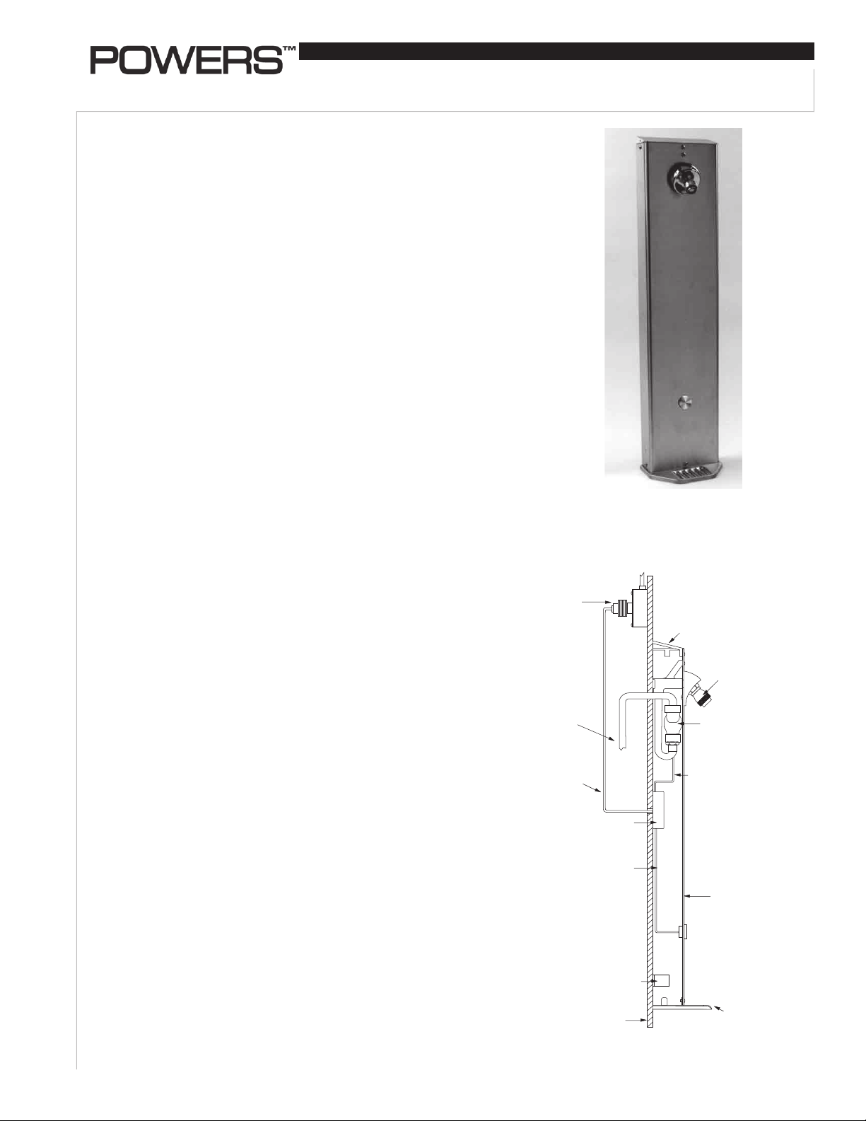
Figure 2
Transformer
(Box Type
Shown)
Chrome-Plated
End Cap
Inlet Piping
(Supplied
by others;
thru-wall or
from ceiling)
Wiring
Control Box
Wiring
Mounting
Bracket
Finished
Wall
Wiring
Typical Shower Installation
Showerhead
(Fixed Shown)
Solenoid
Valve
(Non-metallic
Shown)
Hydropanel
Shrouding
Soapdish
Page 2
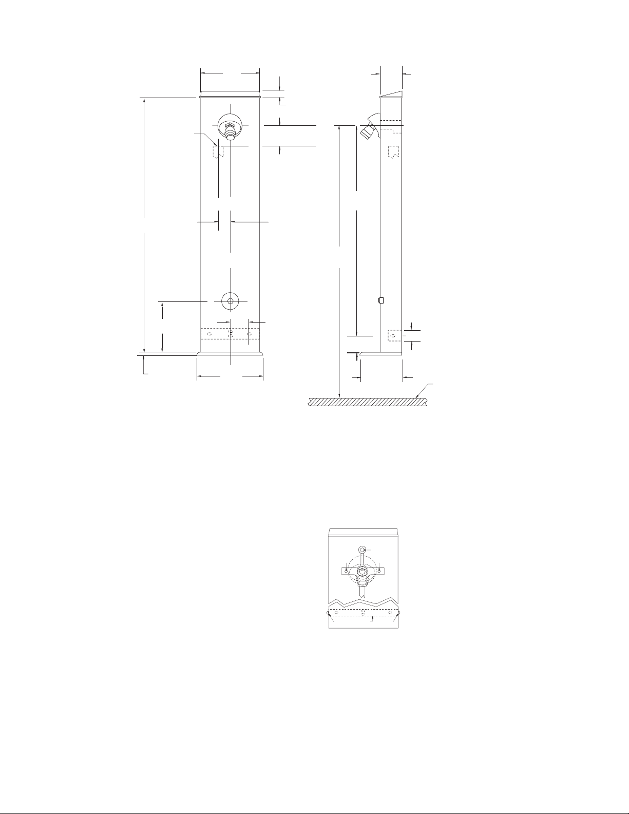
Figure 3
SOLENOID INLET
1/2" NPT Brass
3/4" NPT Non Metallic
30
[762.0]
6
[154.4]
2-1/4
[57.15]
7-3/32
[180.18]
C for Solenoid
L
C for Hydropanel unit
L
11/16
[17.46]
2.5 [63.5] Brass
1.5 [38.1] Non-Metallic
2-1/2
[63.5]
77
[1955.8]
19-1/4
[488.95]
2
[50.8]
2-1/2
[63.5]
1-1/4
[31.8]
For Suggested
Showerhead
Heights see
Installation:
Positioning the
ESP Hydropanel™
II unit
7/16
[11.11]
7-1/2
[190.5]
Front and Side Views - Dimensions of the ESP Hydropanel™ II Pushbutton Shower
Position the ESP Hydropanel™ II Unit
Determine the horizontal position of the unit according to
shower room layout, and mark the centerline (Figure 3). For multiple shower applications, the recommended minimum distance
between the centerline of two units is 36 inches.
Determine the floor-to-showerhead height for the unit.
Recommended heights are listed below:
Men 77" [1955.8mm]
Youth 66" [1676.4mm]
Women 70" [1778mm]
Youth 60" [1524mm]
Determine where the inlet piping will connect to the solenoid.
For the non-metallic solenoid, this connection is typically 1-1/2"
below showerhead height, and 2-1/4" left of centerline. For a
brass solenoid, it is 2-1/2" below showerhead height, and 2-1/4"
left of centerline.
Install the Solenoid and Piping Assembly
The piping and Hydropanel™ II shrouding come pre-assembled
(Figure 4). To detach, remove the screws at the showerhead (A)
and bottom bracket (C and C'). Slide the piping out of shrouding;
the showerhead remains part of the shroud.
WARNING: Before installing solenoid, flush the pipes to
ensure supply water is free of grit and sand.
NOTE: A service stop can be installed directly upstream of the
solenoid to facilitate maintenance and repair.
4-3/4
[120.65]
FLOOR LINE
The non-metallic solenoid has 3/4" NPT end connections, and a
straight through flow path to minimize pressure loss. Make sure
the manual override switch is in the "OFF" position, or else water
will flow regardless of sensor activity.
End Cap
A
B B'
The brass solenoid has 1/2" NPT end
connections.
Connect the supply line to the solenoid. Use only thread sealant on male
threads. Do not use Teflon tape; it
will clog the solenoid valve. Connect
the inlet piping so water flows in the
direction of the arrow on the solenoid.
C
D
Figure 4
To mount the upper bracket of the
C'
piping assembly, drill the holes at the
same height as the top of the showerhead (B and B').
Install Control Box
The control box (Figure 5), with standard cables, can be positioned up to 4 feet from the pushbutton/proximity sensor assembly and up to 2 feet from the solenoid valve. [Optional cable
extensions can extend these distances to 1000 feet from the
sensor assembly, and 300 feet from the solenoid valve.] Remove
the cover. Use the box as a template to mark positions on the
wall for two mounting screws. Drill holes and attach the box.
2
Page 3

Installation cont. n
attach wires
attach wires
Push the two power supply wires (supplied with ESP kit)
through the hole in the side of the Control Box. Insert one wire
into each power connector and tighten each screw for a secure
connection. Replace the cover.
Power connectionsRun-Time Potentiometer
Install the Transformer
The plug-in and box mount
transformers can be positioned
TIME ON
N
I
E
A
R
S
C
E
in a chaseway, closet or ceiling. Each can power up to eight
solenoids. For shower system
maintenance, a remote shutoff
SENSOR SOLENOID
switch can be installed.
WARNING: Do not supply
Sensor Port Solenoid Port
Figure 5
power to or plug in the transformer until all wiring is complete.
Plug-In Transformer
The plug-in transformer will connect to a
110V AC wall outlet. Connect the two power
cord wires from the Control Box (or GCB) to
the screw terminals on the secondary side
of the transformer (Figure 6). Tighten the
screws.
NOTE: The wires can be lengthened with 22
Figure 6
gauge bell wire.
Box Mount Transformer
The box mount transformer will mount
on a 110V AC supply electrical junction box. The "J" box should be inside
the chase wall or above the ceiling.
Connect the power supply wires from
the Control Box (or GCB) to the secondary side of the transformer (Figure
Figure 7
7). Tighten the screws.
ESP System Test
Before attaching shrouding, the ESP system should be tested.
First, position and support the Hydropanel™ shrouding within
all cable limits (on a chair, etc.). Do not turn on power or water
supply yet.
Shower Applications
Insert the plugs from the proximity
sensor and the solenoid into their
labeled ports on the Control Box
(Figure 5). The unit will not operate
Figure 8
properly if the connectors are not in
their correct ports.
Supply power to the transformer, and activate the sensor by
pressing the pushbutton (Figure 8). The solenoid should make
an audible click.
ESP Shower Time Adjustments
NOTE: To prevent repeat cycling, the Piezo sensor has a five
second "lock-out" after the shower has been turned on or off.
During the five seconds, no matter how many times the pushbutton is pressed, the sensor is programmed not to respond.
Also, the sensor is programmed to deactivate the shower if the
button is held in the active position (continuously invading the
proximity sensor's magnetic field).
Shower Applications
The ESP Control Box includes a potentiometer to set maximum
run-time, from 0 to 15 minutes (Factory setting is about 6 minutes). To adjust shower time, remove the cover of the Control
Box. Locate the slotted dial in the center of the circuit board
(Figure 5). With a small screwdriver, rotate the dial in small
increments, clockwise for more time, counterclockwise for less.
Turn dial carefully; overadjusting can damage the potentiometer. After each adjustment, test and time the shower.
Re-Attach the Shrouding
The bottom bracket (Figure 4,D) will attach to the wall 25-1/2"
below showerhead height (see Figure 3). Use the bracket as a
template to mark positions for two mounting holes. Drill holes
and attach the bracket.
The chrome plated end cap (Figure 4) on top of the shrouding
has a section marked to be broken out for vertical and horizontal piping clearance. To remove the marked piece, hit it sharply
with a hammer. Do not remove the entire end cap from the
shrouding.
Connect the outlet side of the solenoid to the showerhead piping by sliding the showerhead nipple (with the shrouding unit)
into the piping assembly. The bottom bracket will fit inside the
shrouding.
Before connecting shrouding with screws, turn on water supply
and activate the sensor to test the system. Water should flow
through showerhead. Press the pushbutton again to deactivate
the shower, then check all connections for leaks.
Use screws to attach the shrouding to the piping bracket and to
bottom mounting bracket (Figure 4, A and C).
Operation n
1) When a bather presses the pushbutton, the sensor sends a
signal through the control box to the solenoid. The solenoid
opens and allows tempered water to flow to the showerhead.
2) If the bather presses the pushbutton again, a signal is sent to
the solenoid to close and consequently shutoff the water.
3) If the bather does not press the pushbutton again, water will
automatically shutoff at the pre-set run-time. After shutoff,
the system is ready for the next user.
NOTE: To prevent repeat cycling, the proximity sensor has
a five second "lock-out" after the shower has been turned on
or off. During the five seconds, no matter how many times
the pushbutton is pressed, the sensor is programmed not to
respond. Also, the sensor is programmed to deactivate the
shower if the button is held in the active position (continuously
invading the proximity sensor's magnetic field).
3
Page 4

System Maintenance n
Routinely (twice a year) perform the following maintenance to
ensure safe continuous operation of ESP Hydropanel™ units.
1. Inspect electrical connections for corrosion.
2. Check for any loose connections. Tighten if necessary.
3. Check solenoid valve for proper operation. Make sure it is
free of dirt and lime build up.
4. Check that temperature of supply water is thermostatically
controlled for safe comfortable bathing.
Maintenance and Troubleshooting n
The following are problems that may occur with the ESP
Hydropanel™ II. Follow the listed steps toward a solution. For
any further problems, call Powers Application Engineering
Deptartment at 1.800.669.5430.
Shower Control:
1. If the shower does not activate when the pushbutton
is pressed:
a. Check that transformer feed wires are securely
attached to terminals at control box and at transformer.
b. Check that power is supplied to the transformer. Also,
use a voltmeter to check that power is being supplied
through the transformer. If power goes into the transformer but does not come out, replace the transformer.
2. If no water flows from showerhead when pushbutton
is pressed:
a. Check that the supply line is open and water is being
supplied.
Solenoid Valve Maintenance n
For brass solenoid: For maintenance instructions, use Powers
Kit #444 183 and refer to “Installation and Maintenance
Instructions,” Series 8210, included with the ESP Hydropanel™
II Kit.
b. Check that the solenoid wires are securely connected.
c. The maximum run-time may have elapsed. Wait 5
seconds for sensor delay, then press the pushbutton
again. For a longer shower-run time, reset potentiometer on control box.
3. If water runs continuously, regardless of sensor activity:
a. FIRST unplug solenoid from the control box.
b. If water continues to run...
• Debris and/or lime build-up may be preventing
solenoid from closing. Dismantle, clean and flush the
solenoid valve (see Solenoid Valve Maintenance).
c. If water stops after disconnecting power...
• The problem is electronic. Check that power wires
are connected properly in the Control Box, and check
all electrical connections.
Parts List n
No. Part # Description
1 444 416 Sensor Assembly for Pushbutton Shower
1A 444 416 Pushbutton Assembly
2 444 175 Solenoid Assembly (non-metallic)
3 444 175 Solenoid Assembly (brass)
4 444 161 Control Box, Individual Pushbutton Showers
5 444 118 Plug In Transformer
6 444 119 Box Transformer
1
1a
2
65
7
3
8
No. Part # Description
7 141 379 Swivel Showerhead
8 141 816 Fixed Showerhead
Not Shown 444 168 Installation Kit, Pusbutton Control Box
Not Shown 444145C Maintenance/Repair Kit, Solenoid (non-metallic)
Not Shown 444145D Diaphragm Repair Kit, Solenoid (non-metallic)
Not Shown 444 183 Maintenance/Repair Kit, Solenoid (brass)
4
A Watts Water Technologies C ompany
IS-P-450P 1030 EDP# 6512206 © 2010 Powers
USA: Phone: 1.800.669.5430 • Fax 1.847. 229.0526 • www.powerscontrols.com
Canada: Phone: 1.888.208.8927 • Fax 1.888. 479. 2887 • www.powerscontrols.ca
 Loading...