

Page 1
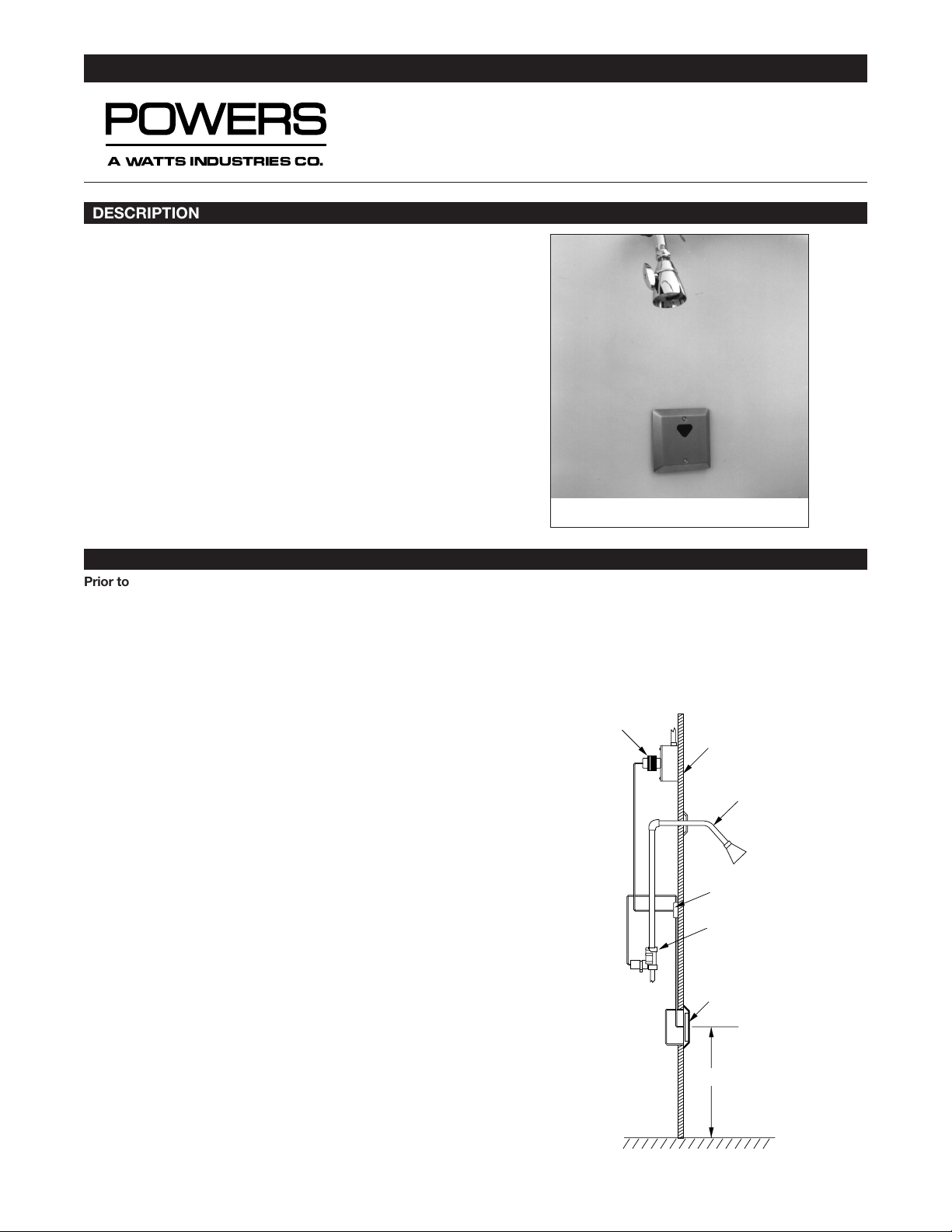
Hydroguard ESP infrared shower systems rely on infrared technology to sense the presence of a user and to immediately turn
on a water supply. The shower automatically shuts off when the
bather steps out of the invisible beam of infrared light, or when
the maximum shower time has been reached. The shower time is
field adjustable from 0 to 14 minutes.
All showers are supplied complete with the sensor assembly,
transformer (plug in or box, as specified), solenoid valve, modular
junction box and mounting hardware.
The following instructions will serve as a guide when installing the
Powers ESP sensor operated showers. As always, good safety
practices and care are recommended when installing electrical
equipment. We suggest that you follow the procedures outlined.
If additional assistance is required, please call the Powers
Application Engineering Department at (847) 673 6700.
TECHNICAL INSTRUCTIONS
Hydroguard ESP
TM
Infrared Sensor Showers
A Watts Industries Co.
DESCRIPTION
Prior to Installation
WARNING
:
• 24V AC Step down transformer must be used for single and
group shower applications.
• Do not allow power transformer wires to touch during wiring,
since this could cause permanent damage to the transformer. To avoid this, do not supply power to, or plug in, the
transformer until all other wiring is complete.
• Since solenoid valves require water free of sand, grit, etc., to
operate properly, flush water lines until water is free of those
materials before connecting solenoid valve.
• All electrical wiring and plumbing should be done in accordance with national/local codes and regulations.
• We recommend the use of stainless steel screws for installation of all components.
TOOLS REQUIRED:
• Slotted and Phillips screwdrivers
• Drill
• Pipewrenches
• Pipe dope/sealing compound
Powers ESP Infrared Showers are supplied with a brass Solenoid
Valve, into which tempered water should be connected. A
Powers thermostatic mixing valve, such as the Hydroguard
Series 430, will ensure safe comfortable water is supplied to your
shower system.
Step 1: Determine Shower Component Layout
Several components, including the shower sensor, control box,
solenoid and transformer, will need to be installed to ensure proper operation of the infrared shower system.
The first location to be identified should be the shower sensor…
the sensor is housed in a Stainless Steel Plate designed for surface mounting onto the shower wall. Once the sensor location is
determined, you can decide on the location of the other components—the solenoid and sensor are typically located within 2 feet
of the modular junction box, but you can use 4 conductor flat
telephone cable and connectors to locate the components up to
as far as 100’ away from the sensor.
INSTALLATION
Modular
junction box
Sensor
assembly
CL of electrical box:
41″ to finished floor
Electrical box
(supplied by others)
Solenoid valve
assembly
Finished
wall
Box transformer
41″
Figure 1: Typical Shower Installation
Showerhead &
arm/flange
Piping supplied
by others
ESP Model 447-10000K100
Form TI447S
Page 2
TI447S Page 2
The solenoid valve should be located as close as possible to the
showerhead it is servicing. Access to the valve must be provided
for maintenance and servicing.
Suggested height for mounting of the sensor for adult men and
women is approximately 41”… adjustments to height should be
made for adolescents and children. Measure the proper height
from the floor… mark shower sensor location with a pencil. Using
a 5/8” drill bit, drill hole for sensor connection cord.
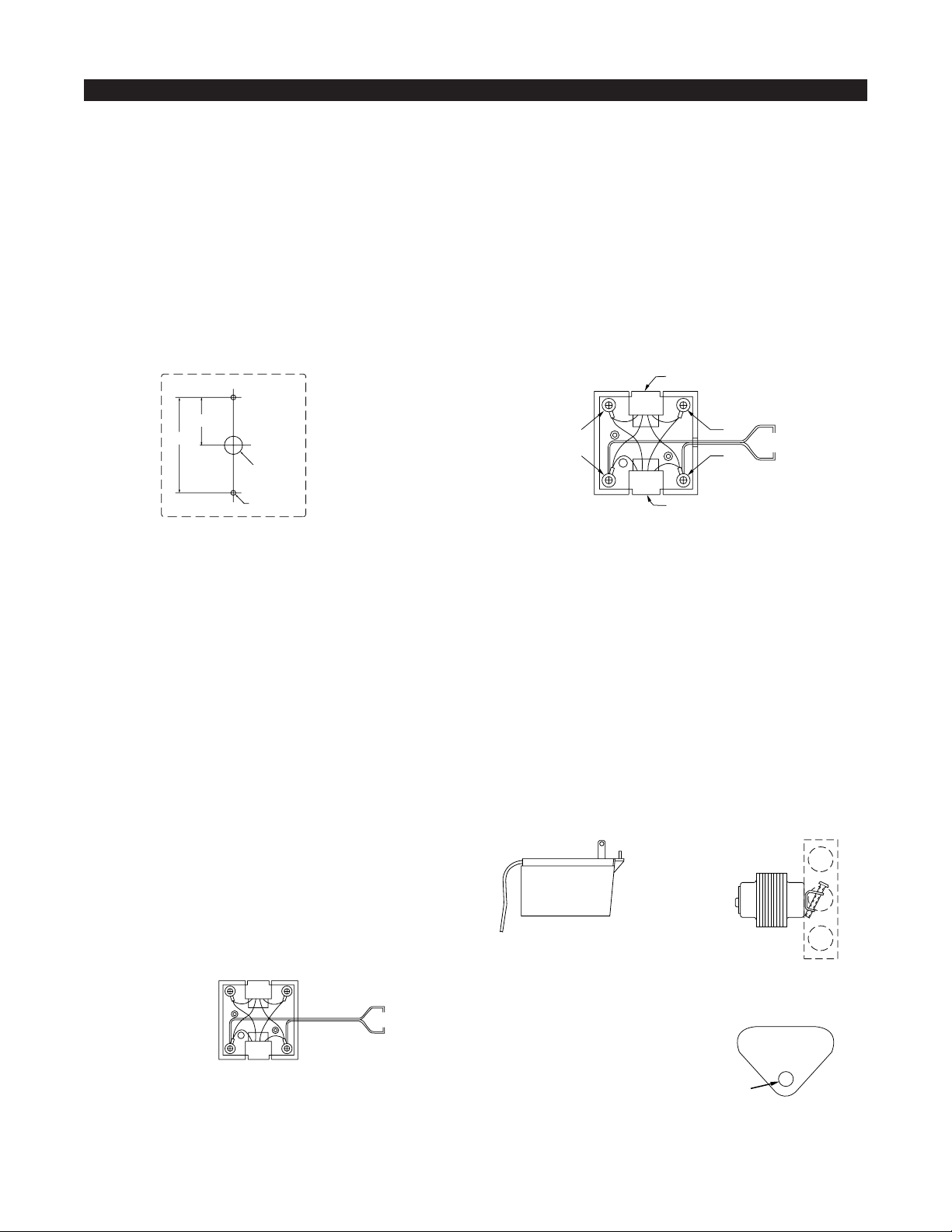
Once you’ve pushed the shower sensor cord through the hole,
use the stainless steel plate as a template, marking the location
of the mounting screws. The shower sensor assembly can be
mounted to a 4 x 2 x 23/16” deep electrical box with screws provided, although it is not necessary to do so. If installing onto wall,
drill 2 mounting holes (refer to figure 2) and install the sensor
assembly.
Do not yet tighten screws since you may need access to the sensitivity and run time potentiometers for final adjustments.
Step 2: Install Solenoid
To facilitate servicing, you may wish to install a service stop
directly upstream of solenoid. Prior to installing solenoid, flush
lines to be sure supply water is free from grit and sand. Solenoid
end connections are 3/4” NPT.
Using thread sealant on male threads only (do not use teflon
tape), connect supply line to solenoid, checking to be sure the
flow is in the proper direction (flow arrow is marked on solenoid
body). For normal operation, check to be sure the solenoid manual override is in the “off” position or water will flow regardless of
sensor activation/deactivation.
Connect outlet side of solenoid to showerhead piping.
Step 3: Install Modular Junction Box
Keeping in mind that the solenoid and sensor must be within 2¢
of the modular junction box (unless you’re using extra cables and
connectors), determine the location for mounting. Using the base
of the box as a template (cover should be removed by unsnapping from base), drill two small holes for mounting of the box.
Install box. (See figure 3.)
Step 4: Transformer Installation
Transformer can be remotely located (in the chaseway, closet or
in ceiling, etc.) and can typically power up to eight shower solenoids.
You may wish to install a remote shut-off switch to shut down power
to showers during maintenance, cleaning or repair.
For single shower applications, connect supply wires to modular
junction box by loosening black and yellow screw terminals of modular junction box. Using the power cord wire supplied, connect one
of the two wires to the yellow terminal, the other to the black terminal, tightening the screws for a sure connection. (Refer to figure 5.)
Replace cover onto Modular Junction Box. Insert the plug from
the solenoid into one receptacle of the modular junction box, and
the plug from the sensor into the other receptable. Either plug
can be inserted into either receptacle of the modular junction box.
Plug In Transformer (see figure 6). This type of Transformer is
designed to be plugged into a 110V AC wall outlet. Transformer
is supplied with a 10’ wire, which can be shortened or lengthened to meet installation requirements using 22 gauge bell wire.
Connect the feed wires to the screw terminals on the secondary
side of the transformer. To avoid permanent damage to the transformer, sensor or solenoid valve, do not plug transformer into
outlet until all wiring has been completed!
Box Mount Transformer (see figure 7). This type of transformer is
designed to be mounted on an 110 VAC supply electrical junction box (“J” box should be mounted inside chase wall or above
ceiling). Run wires from secondary side of transformer to control
box enclosure. To avoid permanent damage to the transformer,
sensor, or solenoid valve, do not supply power to primary side of
transformer until all wiring has been completed.
Step 5: Start Up
Supply power to transformer.
Activate the sensor and check to
be sure the small red activation
light appears in the bottom of
sensor lens. (Refer to figure 8.)
INSTALLATION, CONTINUED
31⁄
4
15⁄
8
5
⁄8 Dia. Hole
3
⁄
16
Dia. Hole
2 places
Shower Sensor
Assembly
Mounting Holes
Overall size of
plate: 4
7
⁄
8
″ square
Figure 2
Sensor Assembly Mounting Holes
Figure 3
Modular Junction Box
Solenoid Valve
or IR Sensor Connector
Red
Yellow
24 VAC to Yellow & Black
24 VAC
Solenoid Valve
or IR Sensor Connector
Black
Green
Figure 5
Modular Junction Box—Wiring
Figure 6
Plug-In
Transformer
Red
indicator light
Figure 8
Sensor Assembly Activation Light
Box Mount
Transformer
24V AC
Secondary
Figure 7
Page 3

If the light is on, the sensor is properly operating… turn on water
supply and reactivate sensor. Water should come through showerhead. Once water is flowing, check all connections for leaks.
Step 6: Sensitivity Adjustment
For single shower applications, the Sensor is factory set to provide a proper sensitivity/distance range for most applications
(18≤ from sensor eye, depending on reflectivity of skin, lighting,
etc.).If range is acceptable, proceed to step 7. If range adjustment is required, you can adjust as follows.
Remove sensor assembly from wall and look at back side. You’ll
see two potentiometers (see figure 9). The upper potentiometer is
for adjustment of the range, from 2≤ to 48≤. Using the small
screwdriver provided, rotate the potentiometer in small increments: clockwise to increase the range, counterclockwise to
decrease the range. After each adjustment, check to see if range
is acceptable.
Make adjustments carefully. Over-adjustment can damage
potentiometer.
Step 7: Shower Time Adjustment
Although the shower will shut off when bather steps away from
the infrared sensor, the shower can also be set to automatically
shut off after a maximum shower time, from 0–14 minutes. The
Sensor Assembly is factory set to provide the maximum shower
time of 14 minutes. If that showertime is acceptable, proceed to
step 8. If showertime adjustment is required, it is easily adjusted
as follows.
Remove sensor assembly from wall and look at back side. You’ll
see two potentiometers (see figure 9): the lower one is for adjustment of the shower run time from 0 to 14 minutes. Using the
small screwdriver provided, rotate the potentiometer in small
increments: clockwise to increase the showertime, counterclockwise to decrease the showertime. After each adjustment, check
to see if showertime is acceptable.
Make adjustments carefully. Over-adjustment can damage
potentiometer.
For multiple shower applications utilizing the group shower control box, all timing, block out and other adjustmnets are programmed into the microprocessor cip...refer to your original
specification form for details. Sensitivity of sensor is still adjusted
at the individual sensor potentiometers.
Step 8: Secure Sensor Assembly
Once final adjustments have been made to sensitivity and runtime potentiometers, secure the sensor assembly using the two
screws supplied. We also suggest using plumber’s putty gasket
(not supplied) around stainless steel plate to prevent water leakage behind the wall. To clean, use a mild soap and water, paying
special attention to ensure no abrasive cleaners are used on the
lens, since scratching may occur.
1. A continuous invisible infrared light beam is emitted from the
sensor assembly.
2. The shower is activated by bather stepping within the
adjustable range of sensor. Immediately after sensor activation, tempered water flows for as long as the user remains
within the range, up to the set maximum shower time.
3. When the bather steps away from the sensor, the water flow
stops automatically. After preset shower time, the flow of
water stops to prevent water waste. It is then ready for the
next user, or for reactivation by the present user.
To clean the shower area but avoid turning off the main water
supply, simply place dark, solid tape (perhaps black electrical
tape) on top of the lens, to block out all light. The sensor should
not activate until the tape is removed. Note that a mild soap may
be used to clean the lens, but abrasive cleaners should be avoided.
To ensure trouble-free performance, routine maintenance is
required.
• Check all electrical connections, making sure they are free of
corrosion and well connected.
• Check solenoid valve to ensure that it is operating properly
and is free of dirt and lime build up.
• Check to be sure the tempered water being supplied to the
shower is at the proper temperature for safe comfortable
bathing.
If the shower does not function properly:
1. Is the red sensor activation light on in the sensor assembly
lens, upon sensor activation? If red LED is not lit after sensor is activated,
• check to see if transformer feed wires are securely attached
to terminals at modular junction box and at transformer.
• check to see if there is power to the transformer, using a
voltmeter. If power is going into the transformer but not coming out of the transformer, replace transformer.
• if transformer is functioning properly and power is being
supplied, replace sensor assembly.
NOTE: If object is within the range of the Sensor when unit is
powered up, the Sensor will not operate until the object is
removed and Sensor reactivated.
2. If sensor light is lit upon sensor activation, but no water
comes from showerhead,
• check to be sure supply line is open and water is being supplied.
• check to see whether solenoid is functioning… check to be
sure manual override is in “off≤ position. If system still fails to
operate, repair or replace solenoid assembly (see solenoid
repair information above).
TI447S Page 3
INSTALLATION, CONTINUED
OPERATION
MAINTENANCE AND TROUBLESHOOTING
Sensing
Distance
(In)
Run Time
(Min.)
+
–
+
–
20 40
014
0
9
Figure 9
Shower Sensor Potentiometers
Page 4

TI447S Page 4
© April 2001 Powers, a Watts Industries Co.
3400 Oakton Street, Skokie, IL 60076 Phone: 800.669.5430 • 847.673.6700 • Fax: 847.673.9044
www.powerscontrols.com
5435 North Service Road, Burlington, Ontario, L7L 5H7 Canada • Phone: 888.208.8927 • Fax: 888.882.1979
A Watts Industries Co.
PARTS LIST
MAINTENANCE AND TROUBLESHOOTING, CONTINUED
• maximum run time may have been reached… sensor will
remain lit although solenoid will close to stop water from
flowing. If additional shower time is desired, reset run time
potentiometer on back of sensor assembly.
3. If water is on all the time, regardless of sensor activation, unplug
solenoid from control box. If water continues to run, problem is
manual and can be rectified by checking the following:
• check for debris and/or lime build-up within the solenoid,
which is preventing it from closing. Dismantle, clean and
flush the solenoid valve.
If, after unplugging solenoid from control box, water stops,
problem is electronic. Check to see if power wires are incorrectly connected within modular junction box or group control box. Refer to instructions above and rewire, checking
electrical connections.
5
3
1
2
4
No. Description Part No.
1 Sensor Assembly 444-141
2 Solenoid Assembly 444-175
3 Installation Kit with Modular Junction Box 444-143
4 Plug In Transformer 444-118
5 Box Transformer 444-119
Form TI447S 0218 EDP# 6512238 Printed in U.S.A.
 Loading...