

Page 1

Shown above: Model 420-RB-E-S-S-0-0
tronic faucets), checkstops (highly recommended) or other
accessories common to Powers’ cabinet supply offering.
DESCRIPTION
Hydroguard Series 420 Under-the-Counter thermostatic tempering valves are designed for all applications where the temperature of generated hot water must be controlled for safe,
economic use. A powerful liquid-filled motor quickly senses
and compensates for temperature fluctuations induced by
water temperature and pressure changes in the supply line.
Rugged construction features cast brass body and corrosionresistant internal components for years of dependable, trouble-free service. Screwdriver stem makes temperature adjustment quick and easy.
For restricted access control, the Series 420 valve can be
housed in a stainless-steel or white baked enamel steel cabinet and can be packaged with solenoid valve(s) (for ESP elec-
SPECIFICATIONS
Valve Construction:
Under-the-Counter thermostatic mixing valve, with heavy cast bronze body and brass stem with screwdriver adjustment.
Capacity..............................................Standard ................................................6 gpm [22.7 L/min]* (±0.5 gpm [1.9 L/min])
High ........................................................8 gpm [30.3 L/min]* (±0.5 gpm [1.9 L/min])
Low......................................................3.5 gpm [13.2 L/min]* (±0.5 gpm [1.9 L/min])
Maximum Hot Water Supply Temperature ......................................................................................................190°F [88°C]
Minimum Hot Water Supply Temperature
(not applicable to low temperature hot water valve) ....25°F [14°C] above set point
Maximum Operating Pressure ................................................................................................................125 psig [862 kPa]
Temperature Ranges........................................................................................................Standard......65–115°F [18–46°C]
High ..........120–175°F [49–79°C]
Low ..................40–90°F [4–32°C]
Maximum Static Pressure........................................................................................................................125 psig [862 kPa]
Minimum Flow and Pressure Differential: Minimum Flow
Minimum Pressure Differential
Standard Capacity ............................................................2.5 gpm [9.5 L/min]......................................10 psi [69 kPa]
High Capacity ....................................................................4.5 gpm [17 L/min] ....................................15 psi [103 kPa]
Low Capacity......................................................................1.0 gpm [3.8 L/min]........................................5 psi [34 kPa]
Shipping Weight................................................................................................................................................5 lbs. [2.3 kg]
The Hydroguard Series 420 Under-the-Counter standard and high capacity valves meet the above operating conditions
as stated in ASSE 1017 (45 psi pressure differential, hot water supply between 140°–180°F [60–82°C], cold water supply
less than 70°F [21°C]).
If your operating conditions vary from those stated in the standard, performance may vary as well. Consult your local
sales representative or a Powers factory engineer to discuss your specific application. All Powers Under-the-Counter
thermostatic mixing valves perform to the requirements of standards ASSE 1017 and CSA B125.
* At 45 psi differential [310 kPa], with hot water supply between 140°–180°F [60–82°C].
TECHNICAL INSTRUCTIONS
Hydroguard Series 420
Under-the-Counter Thermostatic Tempering Valve
OPERATION
Hot and cold water supplies enter the 420
Hydroguard through their respective inlet ports. Both
supplies mix in the chamber containing the valve
assembly. The resulting mixture flows across the
thermostatic motor, and the motor positions the
valve assembly to maintain the desired delivery
water temperature.
Delivery water temperature can be varied by turning
the adjustment stem. Turning the stem counterclockwise raises the temperature, and turning the stem
clockwise lowers the temperature. WARNING: A
valve without checkstops, left in the open position,
even with a downstream shutoff valve used, does
not prevent crossflow.
TI420U
(Operation continued on page 3)
Page 2

2
Page 3
3
OPERATION (continued from p. 1)
If the temperature of the mixture is higher than the
temperature setting, the thermostatic motor actuates
the valve assembly toward the hot water seat. Hot
water flow decreases and cold water flow increases.
Thus the mixture temperature is brought down to the
desired temperature. The reverse occurs when the
mixture temperature is lower than the temperature
setting.
A change in water temperature or pressure of either
hot or cold water supply will cause the thermostatic
motor to reposition the valve assembly to maintain
the desired delivery temperature.
420 Hydroguard supplies tempered water to
self-closing and/or solenoid valves, Powers recommends use of a shock absorber (Powers Part
No. 460-353) on the discharge line. This protects
the 420 Hydroguard thermostatic motor from
damage.
3. Locate the valve as close as possible to outlet
fixture to avoid waste of energy and water
except in applications where the valve is used as
a primary mixing valve to supply an entire building.
4. Correct valve sizing affects valve and system
performance; under- or over-sizing of the mixing
valve(s) can cause poor operation and possibly
injury. Refer to Sizing Information on page 6.
Adherence to these guidelines and recommendations promotes safe product use and ensures proper valve performance.
1. Thermostatic water mixing valves are control
devices which must be cleaned and maintained
on a regular basis. Powers specifies periodic
maintenance at least once a year or immediately after any changes are made to the plumbing
system. Although annual cleaning is recommended, frequency of cleaning depends on
quality of local water conditions. Refer to
Preventive Maintenance on page 4 for recommended cleaning procedure.
2. Quick closing valves may cause damage to the
mixing valve by creating shock waves. When the
SAFETY & PERFORMANCE GUIDELINES
Note: All Powers products are subject to the Terms &
Conditions of Sale and Warranty Information, found in the
current Powers CPL Price List.
Page 4

ALL MODELS
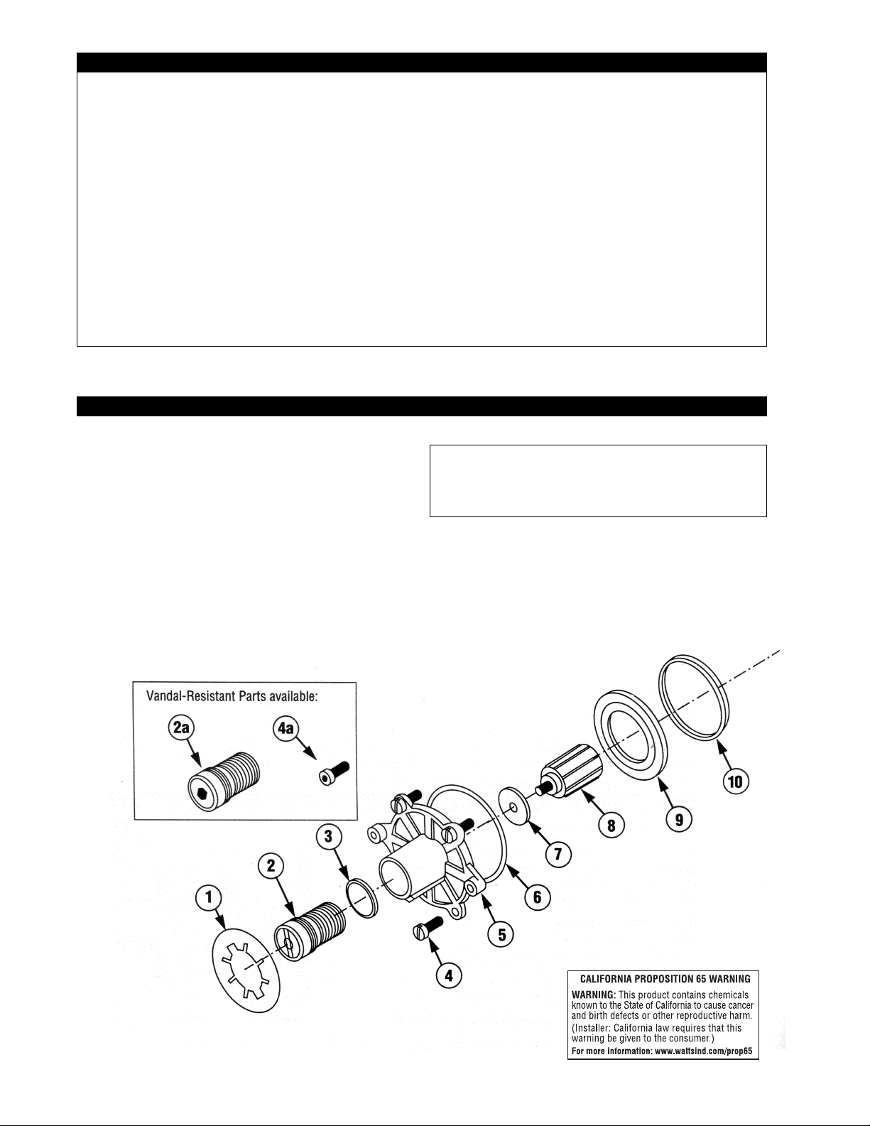
† NOTE: Item available in more than one repair kit. See repair kits on p. 4.
NA = item not available as an individual commercial part.
Item # Product # Description Material
13–19 Valve Assembly
13 Override Stem Brass
14 Cold Water Shut Off Plate Rubber
15 Override Spring Stainless Steel
16 Hot Water Disc Retainer Brass
17 Hot Water Shut Off Disc Bronze
18 Override Spring Retainer Brass
19 Retaining Spring E-Clip Copper
20 227-109 Return Spring Stainless Steel
21 227-389 Hot Water Seat—Low Capacity Noryl
420-155 Hot Water Seat—High Capacity Noryl
420-250A Hot Water Seat—Std. Capacity Noryl
22 N/A Body Bronze
Item # Product # Description Material
1 N/A Nameplate Aluminum
2 420-184A Adjustment Stem Brass
2a 420-184H Vandal-Resistant Adj. Stem Brass
3 047-114 Stem O-Ring Buna-N
4 420-214 Screws (12 per kit) Stainless Steel
4a 080-050 Vandal-Resistant Screws (12) Stainless Steel
5 420-201 Bonnet Brass
6† Bonnet O-Ring Buna-N
7 046-171 Washer Brass
8† Thermostatic Motor —
9 227-233 Retaining Ring Delrin
10 † Combination Seat O-Ring Buna-N
11 † Combination Seat Delrin
12 † Motor Sleeve Brass
PARTS LIST
4
Page 5

Recommended Used for
Problem Kit Type Repair Kit No. Model(s) Includes Items
•Variable or untempered Motor Replacement 420-519V (High temp) 1–9 Thermal Motor, Bonnet O-Ring,
discharge temperature 420-519 (Std. temp) 1–9 Motor Sleeve (6, 8, 12)
420-519W (Low temp) 1–9
•Water leaks at valve shut off, Combination Seat 420-559 (High capacity) 1–9 Combination Seat, Combination Seat Oshut-off disk and/or hot Replacement 420-521 (Std. capacity) 1–8 Ring, Retaining Ring, Bonnet O-Ring
water seat have been 420-559 (Std. capacity) 9 (6, 9, 10, 11)
replaced 420-522 (Low capacity) 1–9
• Low flow, desired temp- Low Temperature 420-203 1-8 Bonnet O-Ring,Combination Seat O-Ring
erature cannot be reached Hot Water 420-557 9 (Mdls. 1-8 kit only), Combination Seat
Conversion Kit (Mdl. 9 kit only), Valve Assembly
(Mdl. 9 kit only)
•Water leaks at bonnet/body O-Ring Kit 420-524 1–9 Stem O-Ring, Bonnet O-Ring,
Combination Seat O-Ring (3, 6, 10)
•Variable or untempered dis- Valve Replacement 420-563 (High capacity) 1–9 Bonnet O-Ring, Valve Assembly
charge temperature continues 420-525 (Std. capacity) 1–8 (6, 13–19)
after motor replacement 420-560 (Std. capacity) 9
420-560 (Low capacity) 1–9
•Worn hot water seat Valve and Hot 227-340 (Std. capacity) 5-8 Bonnet O-Ring, Combination Seat O-Ring,
Water Seat 420-561 (Std. capacity) 9 Valve Assembly, Return Spring, Hot Water
Seat (6, 10, 13-19, 20, 21)
REPAIR KIT PART NUMBERS
Figure 2.
3. Flow is untempered hot or cold water…
• accumulation of lime deposits in hot water pipes,
restricting the flow of hot water
• thermostatic motor failure; replace with new thermostatic motor
• hot and cold water supplies are connected to the
wrong ports
4. Maximum temperature specified for the 420
Hydroguard cannot be obtained…
• accumulation of lime deposits in hot water pipes,
restricting the flow of hot water
• hot water supply temperature is too low
5. Variable discharge temperature occurs…
• extreme pressure variations in supply lines
• valve operating below minimum capacity requirements
PREVENTIVE MAINTENANCE
Every Six Months: Check and adjust the maximum
temperature setting (see instructions below).
Every Twelve Months:
1. Shut off water supply.
2. Open up checkstops (if any).
3. Clean strainers (if any) and check for free movement of checkstop poppet.
4. Remove the bonnet and check for freedom of
movement of internal components.
5. Test the thermostatic motor as described in
Thermostatic Motor Testing Section (page 5).
6. Replace seals if cracked, cut, or worn.
7. Reassemble.
8. Adjust screwdriver stem to desired temperature.
1. The flow of water is less than desired…
• valves upstream from supply not fully open
• low supply pressures
• accumulation of lime deposits in hot water pipes,
restricting the flow of hot water
• checkstops not fully open
• clogged strainer screens in the checkstops
• clogged hot water seat
2. Flow of water is completely shut off…
• valves upstream from supply completely closed
• failure of cold water supply pressure (the 420
Hydroguard is designed to shut off on a cold
water supply failure)
• checkstops completely closed
TROUBLESHOOTING
Screwdriver
adjustment
stem
5
Page 6

NOTE:When replacing hot water seat, do not
over tighten!
Figure 6.
The hot water seat can be removed with a 7⁄8”
(22mm) socket wrench. (Max. 40 in–lbs. torque.)
NOTE: After completing any maintenance/repairs,
check maximum discharge temperature 115°
(46°C). Reset if necessary.
Pull out the combination seat with a pair of pliers,
pulling on the two opposing lugs. One plier can be
used by alternately pulling on the two opposite
lugs until the seat can be removed by hand. Pull
out the valve assembly and return spring as
shown in Figure 5.
Figure 5.
Figure 4.
Figure 7.
1. Remove the thermostatic motor. Make the following test to determine whether the thermostatic
motor is in operating condition.
2. Thermostatic motor bellows should offer firm, not
spongy resistance to a rigid blunt object inserted
inside the bellows. If it does not offer firm resistance, the thermostatic motor is not fully charged
and should be replaced.
3. Place the thermostatic motor sleeve in the motor
as shown in Figure 7. Immerse the thermostatic
motor into 75°F (24°C) water for a few minutes.
The thermostatic motor should cause an approximate 1/32″ (0.8mm) travel with the 25° (13°C) temperature difference. In other words, the top of the
sleeve should be approximately 1/32″ (0.8mm)
higher at 100°F (38°C) than it was at 75°F (24°C). If
this distance is much less, the thermostatic motor
has lost part of its charge and should be replaced.
THERMOSTATIC MOTOR TESTING
A new thermostatic motor can be substituted. Use pliers to separate motor from stem. Locate the pliers
near washer. To avoid damage, be certain not to
squeeze thermostatic motor too firmly. (See figure 4.)
Remove four bonnet screws and pull out bonnet
assembly. The motor and motor sleeve should come
out with the bonnet. If not, they can be easily pulled
out. When reassembling, the open end portion of the
motor sleeve should be projecting out of the motor.
SERVICING
(Before assembling valve, make certain both water supplies to the valve are shut off.)
Depth distance
should be 1/32″
Bonnet
Screws
Figure 3.
6
Page 7

DIMENSIONAL DATA AND CHECKSTOPS
Figure 8. Nameplate
SIZING
The flow chart below indicates the Hydroguard Series
420 discharge capacity in gpm for various pressure
differentials (the difference between the lowest inlet
pressure and the discharge pressure at the valve).
Valve sizing affects the performance and reliability of
the valve. Under- or over-sizing of the mixing valve(s)
can cause poor operation and possibly injury.
Warning: This is a water tempering device and is not
intended or designed for point-of-use shower applications. There is no limit stop. It is strongly recommended that checkstops be installed with this valve
even when a downstream shutoff is used.
MODEL IDENTIFICATION
To be sure you are installing appropriate parts into your
valve, determine the model number. The easiest way to
do that is to look at the date code (found on the nameplate of the valve). The date code (not to be confused
with the product or part number) is a four-digit code. Its
purpose is to record the model/version number of the
product itself and the date of manufacture. (See circle
"B" in the figure below for location of date code.)
In the example below, the Date Code is labeled by circle "B". The first digit, 8, indicates the model number.
The nameplate also indicates the temperature range of
the valve. In the figure below, circle "A" shows the location of the temperature range: "115" (a standard valve).
9
1
⁄ 16
(230)
Type D
7
3
⁄ 4
(197)
Type A, C
5
7
⁄ 8
(149)
Type E
7
Page 8

© April 2002 Powers, a Watts Industries Co.
3400 Oakton Street, Skokie, IL 60076 Phone: 800.669.5430 • 847.673.6700 • Fax: 847.673.9044
www.powerscontrols.com
5435 North Service Road, Burlington, Ontario, L7L 5H7 Canada • Phone: 888.208.8927 • Fax: 888.882.1979
TI420U 0218 EDP# 6508930 Printed in U.S.A.
 Loading...