

Page 1
INSTALLATION
Installation should be in accordance with accepted plumbing practices. Flush all piping thoroughly before installation.
1. Position mixer 2
1
⁄2″ (64mm) from inlet center to finished
wall surface. Facing front of mixer, connect hot water to
left side (labeled “HOT”) and connect cold water to right
side (labeled “COLD”).
2. When copper tubing is used, flare fittings are recommended. If flared fitting cannot be used, then the balancing chamber cartridge must be removed before
soldering near the Hydroguard body. Inlet checkstops
with direct sweat straight or 90° angle or straight with
1
⁄2″ NPT connections are available. To remove the bal-
ancing chamber cartridge, remove the four bonnet
screws and lift off the bonnet. Pull cartridge out with
either pliers or cartridge puller #401-202. Before replacing the cartridge, lubricate the side O-rings with a small
amount of grease or soap.
3. Three port bodies can be
top or bottom outlet. Unit is fac-
tory-assembled for top outlet installation. See Figure 1.
For shower unit, pipe top outlet directly to showerhead.
If bottom outlet (or reversed outlets) is required, place
mixer stem in closed position (full clockwise) and
remove O-ring and Stop C (Figure 5). Rotate stem 180°
and replace stop in its initial position.
With mixer in closed position, the notch in
top spline on
the stem (Figure 3) must face the outlet for
standard
inlets (cold water to cold port). For reversed inlets (cold
water to hot port), the notch must face way from the
outlet port.
Hot and cold inlets should also be identified to avoid
confusion during fixture maintenance.
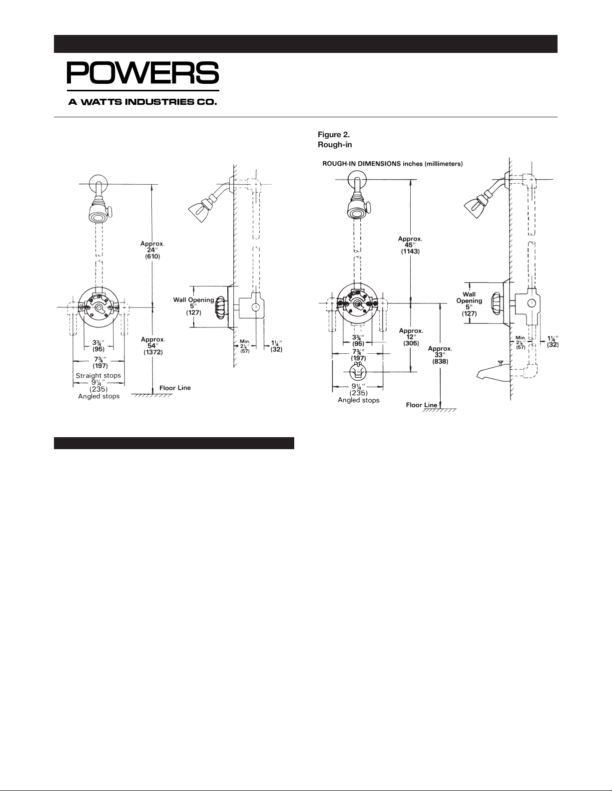
4. A 4-port valve has a double outlet body. See Figure 2.
The top outlet “S” is piped to the showerhead. The bottom outlet “Tub” is piped directly to a diverter type spout.
There is a built-in diverter fitting in the Hydroguard so it is
not necessary to use a twin ell. Be sure that “Tub” is
piped to the tub. If the outlet connections are crossed,
the Hydroguard will not function properly.
5. Slide roughing-in guide onto mixer stem until it contacts
temperature stop on stem. Facing front of mixer, the
words, “Front Finished Wall Guide” can be read. Position
mixer so finished wall surface will be within
3
⁄4″ (19mm)
rim on the guide. This ensures the center line of the
mixer connections will be 2
1
⁄2″ (64mm) from the finished
wall surface. After wall is finished, remove rough-in
guide. Before assembling dial to mixer body, attach gasket to inside dial and sides. Allow approximately
1
⁄8″
(3.2mm) of gasket to protrude past dial edge. Attach dial
to mixer body with two screws furnished. Place dial
insert inside dial. Secure with retainer (rubber). Cover
stem with sleeve, fasten lever handle to stem with screw
provided. For lucite handle, use plug button provided.
Figure 4 shows typical relationship of parts.
INSTALLATION INSTRUCTIONS
Hydroguard Pressure Balancing Valves
Series 410
A Watts Industries Co.
Figure 2.
Rough-in dimensions
inches (millimeters)
Figure 1.
Rough-in dimensions
inches (millimeters)
Form II410
Page 2
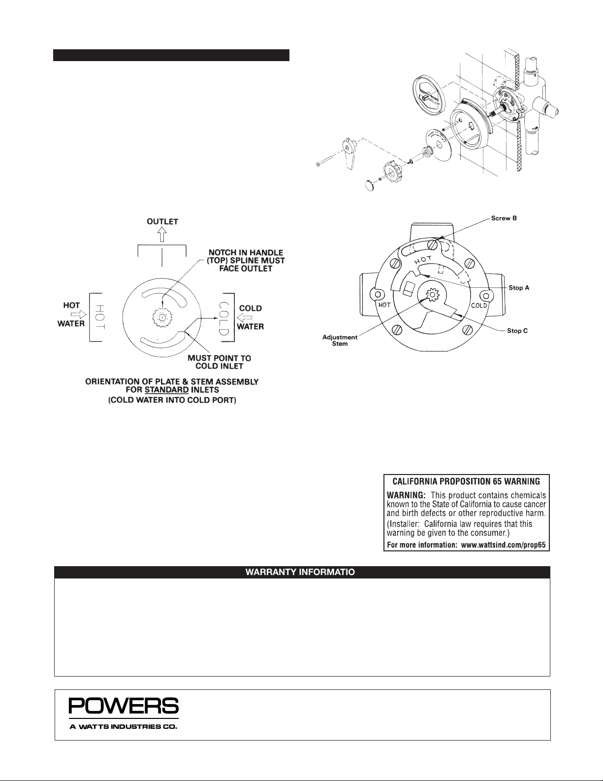
MAXIMUM TEMPERATURE SETTING
6. (Refer to Figure 5.) This must be set on the job. Mixer
will pass full HOT water. Loosen screw B (do not
remove). Rotate stem to get desired maximum temperature. Move stop A until it touches stop C. Tighten
screw B.
Note: With high (over 140°F [60°C]) hot water, remove
screw B, turn stop A over as shown by dashed lines
(the word “HOT” will face in), replace screw B. Reset
stop A per above.
CAUTION. Adjustable stop A must be present for proper installation.
For further information on repair and
maintenance, see Technical Instruction.
II410 Page 2
Figure 3.
Figure 4.
Figure 5.
Reprinted © May 2001 Powers, a Watts Industries Co.
3400 Oakton Street, Skokie, IL 60076 Phone: 800.669.5430 • 847.673.6700 • Fax: 847.673.9044
www.powerscontrols.com
5435 North Service Road, Burlington, Ontario, L7L 5H7 Canada • Phone: 888.208.8927 • Fax: 888.882.1979
A Watts Industries Co.
WARRANTY INFORMATION
Powers warrants that the equipment manufactured by it is free from defects in material and workmanship and, without charge, equipment
found to be defective in material and workmanship will be repaired, or at Seller’s option, replaced F.O.B. original point of shipment, if writ-
ten notice of failure is received by Seller within one (1) year after date of shipment, provided said equipment has been properly installed,
operated in accordance with Seller’s instructions, and provided such defects are not due to abuse or chemical decomposition by chemical
or galvanic action. This express warranty is in lieu of and excludes all other warranties, guarantees, or representations, express or implied.
There are no implied warranties for merchantability or of fitness for a particular purpose. The Seller assumes no responsibility for repairs
made on Seller’s equipment unless done by Seller’s authorized personnel, or by written authority from the Seller. The Seller makes no guar-
antee with respect to material not manufactured by it.
Form II410 0218 EDP# 6512218 Printed in U.S.A.
 Loading...