

Powers 400 User Manual
1. Flush all piping thoroughly before installing.
2. Position mixer 2–1/2
″ from center line of inlets to face of
finished wall. Facing front of mixer, connect hot water to
left side, and cold water to right side. Inlet connections
must be piped correctly for proper operation of Mixer.
Connect hot water inlet to side labeled “H” on bonnet
label, or “HOT” on port label.
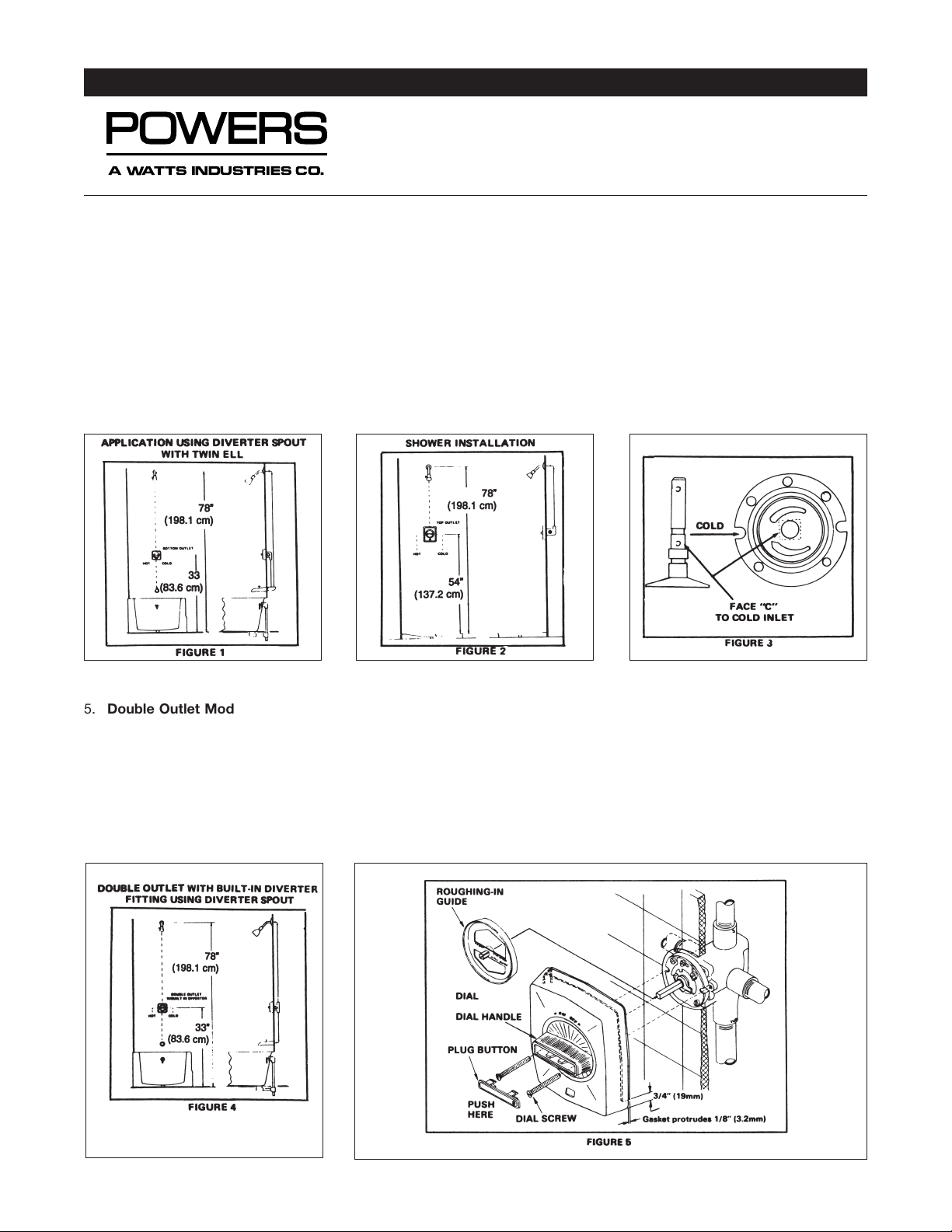
3.
Single Outlet Model can be top or bottom mounted.
See Figures 1 and 2. Unit is factory assembled for top
outlet installation. For shower use only, pipe top outlet
directly to shower head. If bottom outlet is required (or
revered inlets), place mixer stem in closed position (full
clockwise) and remove O-ring and Stop (Figure 7). Rotate
stem 180° and replace Stop in its initial position. The letter “C” (stamped on side of stem, Figure 3) must face the
cold water inlet when mixer is shut off. Hot and cold
inlets should also be identified to avoid confusion during
future maintenance.
4. Installation should be in accord with accepted plumbing
practices.
TECHNICAL INSTRUCTIONS
Hydroguard™ Dial Assembly
Model 6
A Watts Industries Co.
5. Double Outlet Model. See Figure 4. The top outlet “S”
is piped to the shower head. The bottom outlet “Tub” is
piped directly to P diverter type spout, There is a builtin diverter fitting in the Mixer so it is not necessary to
use a twin ell. Be sure that “Tub ” is piped to the tub. If
the outlet connections are crossed, the Mixer will not
function properly.
6. Side Roughing-in guide onto mixer stem until it contacts
temperature stop on stem facing front of mixer, the
words “FRONT FINISHED WALL GUIDE” can be read.
Position mixer so finished wall surface will be within the
3/4
″ rim on the guide. This insures the center line of the
mixer connections will be 2-1/2 inches (64 mm) from the
finished wall surface. After wall is finished, remove guide.
Form TI401
TI401 Page 2
Reprinted © April 2001 Powers, a Watts Industries Co.
3400 Oakton Street, Skokie, IL 60076 Phone: 800.669.5430 • 847.673.6700 • Fax: 847.673.9044
www.powerscontrols.com
5435 North Service Road, Burlington, Ontario, L7L 5H7 Canada • Phone: 888.208.8927 • Fax: 888.882.1979
A Watts Industries Co.
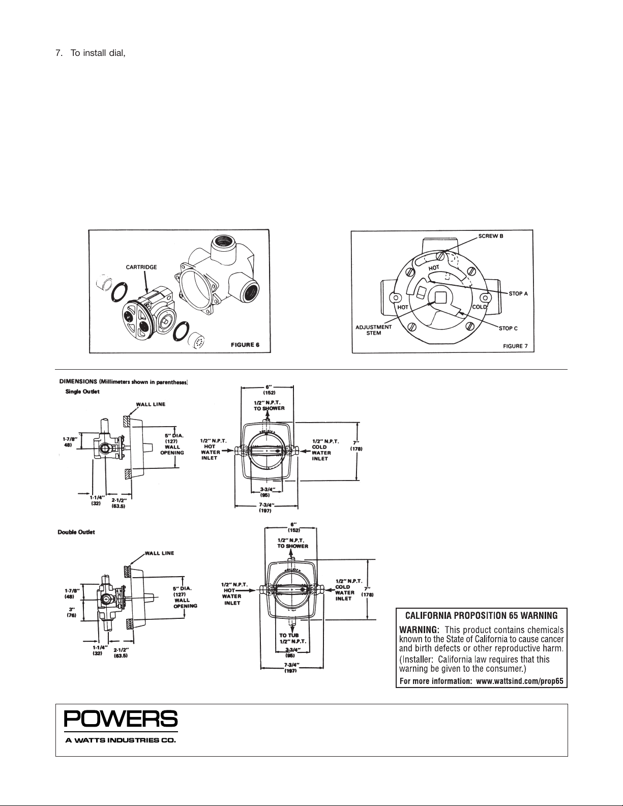
7. To install dial, remove plug button, peel backing off gasket and attach gasket to inside dial top and sides allowing approximately 1/8
″ (3.2mm) of gasket to protrude
past dial edge. Place dial over stem, and attach it to
mixer body with 2 screws provided. Dial handle must be
in horizontal position. Install plug button by snapping it
into handle with HOT–COLD indicator on right. NOTE: To
remove plug button, press indicator marking with thumb,
and snap out. Figure 5 shows relationship of ports.
8. When copper tubing is used flared fittings are recommended. If flared fittings cannot be used, the balancing
chamber cartridge must be removed before soldering
near the Hydroguard body. Inlet checkstops with direct
with direct sweat connections are available in both
straight in and 90° angle configurations.
To remove the balancing chamber cartridge, remove the
four bonnet screws and lift off the bonnet. Pull out the
cartridge, with either pliers or cartridge puller. Before
replacing the cartridge, lubricate the side O-rings with a
small amount of grease or soap. Figure 6 shows body,
cartridge relationship.
9.
Maximum Temperature Setting (Refer to figure 7). This
must be set on the job. Mixer will pas full HOT water.
Loosen screw B (do not remove). Rotate stem to get
desired maximum temperature. Move stop A until it
touches stop C. Tighten screw B. Special Case—with
high (over 140°F [60°C]) hot water. Remove screw B,
turn stop A over as shown by dashed lines (the word
“HOT” will face in) replace screw B. Reset stop A per
above. CAUTION: Adjustable stop A must be present
for proper operation.
Form TI401 0218 EDP# 6512236 Printed in U.S.A.
 Loading...