

Page 1

This Manual is Bookmarked
Operating Instructions and Parts Manual
8-inch Parallelogram Jointer
Model PJ-882
WMH TOOL GROUP
2420 Vantage Drive
Elgin, Illinois 60123 Part No. M-1610079
Ph.: 800-274-6848 Revision A 1/05
www.wmhtoolgroup.com Copyright © WMH Tool Group
Page 2

This manual has been prepared for the owner and operators of a Model PJ-882 Jointer. Its purpose,
aside from machine operation, is to promote safety using accepted operating and maintenance
procedures. To obtai n maximum lif e and effici ency from your jointer and t o aid in using i t safely, please
read this manual thoroughly and follow the instruc tions carefully.
Warranty and Service
WMH Tool Gr oup warrants ever y product it sell s. If one of our tools needs s ervice or repai r, one of our
Authorized Repair St ations located throughout the United States can provide quic k service or information.
In most cases, a WM H Tool Group Repair Station c an as si st in authorizi ng repair work, obtaining parts, or
perform routi ne or m ajor maintenance repair on your Powermatic product.
For the nam e of an A uthoriz ed Repair St ation in your area, pl ease call 1-800-274-6848, or v isit our web
site at www.wmhtoolgroup.com
More Information
Remember, WMH Tool Group i s consistently adding new products to the li ne. For complete, up-to-dat e
product information, check with your local WMH Tool Group distributor, or visit our web site at
www.wmhtoolgroup.com
WMH Tool Group Warranty
WMH Tool Group makes every effort to assure that it s produc ts meet high quality and durability standards
and warrants to the original retail consumer/purchaser of our products that each product be free from
defects in mat erials and workmanship as foll ows: 1 YEA R LIMITED WARRANTY ON ALL PRODUCTS
UNLESS SPECIFIED OTHERWISE. This Warranty does not apply to defects due directly or i ndirectly to
misuse, abuse, negl igence or acc idents, norm al wear-and-tear , repair or alterati ons outside our f aciliti es,
or to a lack of maintenanc e.
WMH TOOL GROUP LIMITS ALL IMPLIED WARRANTIES TO THE PERIOD SPECIFIED ABOVE,
BEGINNING FROM THE DATE THE PRODUCT WAS PURCHASED AT RETAIL. EXCEPT AS STATED
HEREIN, ANY IMPLIED WARRANTIES OR MERCHANTABILITY AND FITNESS ARE EXCLUDED.
SOME STATES DO NOT ALLOW LIMITATIONS ON HOW LONG THE IMPLIED WARRANTY LASTS,
SO THE ABOVE LIMITATION MAY NOT APPLY TO YOU. IN NO EVENT SHALL WMH TOOL GROUP
BE LIABLE FOR DEATH, INJURIES TO PERSONS OR PROPERTY, OR FOR INCIDENTAL,
CONTINGENT, SPECIAL, OR CONSEQUENTIAL DAMAGES ARISING FROM THE USE OF OUR
PRODUCTS. SOME STATES DO NOT ALLOW THE EXCLUSION OR LIMITATION OF INCIDENTAL
OR CONSEQUENTIAL DAMAGES, SO THE ABOVE LIMITATION OR EXCLUSION MAY NOT APPLY
TO YOU.
To take advantage of this warranty, the product or part must be returned for examination, postage
prepaid, to an Authorized Repair Station designated by our office. Proof of purchase date and an
explanati on of the complaint m ust accompany the merchandi se. If our inspecti on discloses a defec t, we
will either repair or replace the product at our discret i on, or ref und the purc hase price if we cannot readi l y
and quickly provide a repai r or replac ement. We will return the repai red product or replacem ent at WMH
Tool Group’s ex pense, but if it is determ ined there i s no defect, or that the def ect resulted f rom causes
not within the scope of WMH Tool Group’s warranty, then the user must bear the cost of storing and
returning t he product . This warranty gives you specif ic legal ri ghts; y ou may also hav e other ri ghts, whic h
vary from state t o state.
WMH Tool Group sells through distribut ors only. Members of the WMH Tool Group reserve the right to
effect at any time, wit hout prior notice, alter ations to parts, fittings and accessory equi pment, which they
may deem necessary for any reason whatsoever.
2
Page 3

Table of Contents
Warranty and Servic e ..............................................................................................................................2
Table of Contents....................................................................................................................................3
Warning...................................................................................................................................................5
Introduction.............................................................................................................................................. 7
Description..............................................................................................................................................7
Specifications..........................................................................................................................................7
Unpacking ...............................................................................................................................................8
Contents of the Shipping Container............................................................................................. .........8
Installation and Assembly ........................................................................................................................9
Installing Switch Arm..........................................................................................................................10
Installing Cutt erhead Guard................................................................................................................10
Dust Collection...................................................................................................................................11
Grounding Instructions...........................................................................................................................11
Extension cords..................................................................................................................................12
230 Volt, Single Phase Operation.......................................................................................................12
Three Phase Operation......................................................................................................................12
Adjustments........................................................................................................................................... 13
Drive Belt Tension ..............................................................................................................................13
Drive Belt Replacement......................................................................................................................14
Fence Movement...............................................................................................................................14
Fence Stops.......................................................................................................................................15
Fence Removal..................................................................................................................................16
Locking Handles ............................................................................................................................... ..16
Table and Knife Adj ustments..............................................................................................................16
Setting Tables Parallel........................................................................................................................17
Setting Knives at Correct Height and Parallel To O utf eed Table..........................................................18
Outfeed Table Stop Screws................................................................................................................22
Setting Inf eed Table (Depth of Cut) ....................................................................................................22
Infeed Table Depth Stop.....................................................................................................................22
Infeed Table St op Scr ews...................................................................................................................23
Replacing Kniv es in the Cutterhead....................................................................................................23
Elimina t in g “P lay ” in Ta b les................................................................................................................24
Operating Controls.................................................................................................................................24
Operation...............................................................................................................................................24
Hand Placement.................................................................................................................................25
Surfacing............................................................................................................................................25
Edge Jointing .....................................................................................................................................25
Rabbeting ..........................................................................................................................................26
Jointing Short or Thin Work................................................................................................................26
Jointing Warped Surfaces...................................................................................................................26
Beveling.............................................................................................................................................26
Direction of Grain...............................................................................................................................27
Skewing (Shear Cutting).....................................................................................................................27
Maintenance..........................................................................................................................................28
Sharpening Knives.............................................................................................................................28
Cutterhead Repair s ............................................................................................................................29
Optional Accessories .............................................................................................................................32
Replacement Parts................................................................................................................................32
Parts List: Cutterhead Assembly .........................................................................................................33
Parts List: Fence Assembly................................................................................................................ 34
Fence Assembly.................................................................................................................................35
Parts List: Outfeed Table and Base Assembly ....................................................................................36
Outfeed Table and Base Assembly.....................................................................................................37
Parts List: Inf eed Table Assembly.......................................................................................................38
Infeed Table Assembly.......................................................................................................................40
Parts List: Stand A ssembly .................................................................................................................41
Stand Assembly .................................................................................................................................43
3
Page 4

Electrical Connections – 1 Phase, 230 Volt ............................................................................................44
Electrical Connections – 3 Phase, 230 Volt ............................................................................................45
Electrical Connections – 3 Phase, 460 Volt ............................................................................................46
4
Page 5

Warning
1. Read and understand the entire owners manual bef or e attempting assembly or operati on.
2. Read and understand the warnings po sted on the machine and i n this manual. Failure to comply with
all of these warnings m ay cause seriou s i njury.
3. Replace the warning labels if they become obscured or removed.
4. This joint er i s designed and intended for use by properly tr ained and ex per ienced personnel onl y . If
you are not familiar with the proper and safe operation of a jointer, do not use until proper training
and knowledge have been obtained.
5. Do not use this joint er for other than its intended use. If used for other pur pose s, WMH Tool Group
disclaims any real or implied warranty and holds itself harmless from any inj ur y that m ay result from
that use.
6. Always wear approved safety glasses/fac e shields while using this j oi nter. Everyday eyeglasses only
have impact resistant lenses; they are not safety glasses.
7. Before operating this jointer, rem ov e tie, rings, watches and other jewelry , and roll sleeves up past
the elbows. Remove all loose clothing and confi ne long hai r . Non-sl ip footwear or anti- skid floor
strips are recommended. Do not wear glov es.
8. Wear ear protector s (plugs or muffs) during ext ended peri ods of oper ation.
9. Some dust created by power sanding, sa wing, grindi ng, drilling and other construction activities
contain chemi c als known to cause cancer, birth defects or other reproductive harm. Some examples
of these chemic als are:
• Lead from lead based paint.
• Cry stalline silica from bricks, cement and other m asonry pr oduc ts.
• Ar seni c and c hr om ium from chemically treated lum ber .
Your risk of exposure varies, depending on how often you do this type of work. To reduce your
exposure to these chemicals, work in a well-ventilated area and work with approved safety
equipment, such as face or dust masks that are specifically designed to filter out microscopic
particles.
10. Do not operate this machine while tired or under the influence of dr ugs, alcohol or any medication.
11. Make certain t he switc h is i n the OFF position before connecting the machine to the power supply.
12. Make certain t he machine is properly grounded.
13. Make all machine adjustments or maintenance with the machine unplugged from the power source.
14. Remove adjusti ng k ey s and wrenches. Form a habit of checking to see that keys and adjusting
wrenches are removed from the machine before turning it on.
15. Keep safety guards in place at all times when the machine is in use. If r em ov ed for maintenance
purposes, use extreme caution and replace the guards immediately.
16. Check damaged parts. Before further use of the machine, a guar d or other part that is damaged
should be carefull y c hec k ed to det ermine that it will operate properly and perform its intended
function. Check for alignment of moving parts, binding of moving parts, break age of parts, mounting
and any other conditions that may affect its operation. A guard or other part that is damaged should
be properly repaired or replaced.
17. Provide for adequat e space surrounding work area and non- glare, overhead lighting.
18. Keep the floor around the machine clean and free of scrap material, oil and grease.
19. Keep visit or s a safe di stanc e from the work area. Keep children away.
20. Make your workshop chil d pr oof with padlocks, master switc hes or by r em ov ing starter keys.
21. Give your work undiv ided attention. Looking ar ound, carrying on a conversati on and “ horse-play” are
careless acts that can r esul t in serious injury.
22. Maintain a balanced stanc e at all times so that you do not fall or lean against the knives or other
moving part s. Do not over r eac h or use exc essive force to perform any machi ne oper ation.
5
Page 6

23. Use the right tool at the corr ec t speed and feed rate. Do not force a tool or attac hm ent t o do a job for
which it was not designed. T he ri ght tool will do the job better and safer.
24. Use recommended accessories; improper accessories may be hazardous.
25. Maintain tool s with c ar e. Keep k nives sharp and clean for the best and safest performance. F ollow
instructions for lubricating and changing accessories.
26. Turn off the machi ne before cleaning. Use a brush or compressed air t o r em ov e chips or debris —
do not use your hands.
27. Do not stand on the machine. S erious injury could occur if the machine tips over.
28. Never leave the machine running unattended. Turn the power off and do not leave the machine until
it comes to a complete stop.
29. Remove loose it em s and unnecessary work pieces from the area before starting the machine.
30. When working a piec e of wood on the j ointer, follow the 3-inch rul e: T he hands must never be closer
than 3 inches to the cutter head at any time.
31. Always use a hold-down or push bloc k when surfacing stock.
32. Do not joint materi al short er than 8 “, narrower than 3/4” or less than 1/4” thick.
33. Do not make cuts deeper than 3/4” when rabbeting. On other cut s such as edging, surfacing, etc.,
depth of cut should not be ov er 1/16” to avoid overloading the machine and to minimize chance of
kickback.
34. Never apply pressure to stock directly over the cutter head. This may result in the stock tipping into
the cutterhead along wi th the operator’s fingers. Never back the workpiece toward the infeed table.
Familiarize you r self with the following safety no tices used in this manual:
This means that if precautions are not heeded, it may result i n minor injury and/or
possible machine damage.
This means that if precautions are not heeded, it may result i n serious injury or possibly
even death.
- - SAVE THESE INSTRUCTIONS - -
6
Page 7

Introduction
This manual is provided by W MH Tool Group cov ering the safe oper ation and mai ntenance procedure s
for a Model PJ -882 Jointer. This manual contains instr uctions on i nstall ation, saf ety precautions, general
operating proc edures, maintenance i nstructions and part s breakdown. This mac hine has been designed
and constructed to pr ovi de years of troubl e free operation if used in accor dance with instr ucti ons set forth
in this manual . If ther e are any que sti ons or com m ents, please cont act ei t her your loc al suppl ier or W MH
Tool Group. WMH Tool Group can also be reached at our web site: www.wmhtoolgroup.com.
Description
The Model PJ-882 Jointer is built upon a parallelogram design. This design allows independent
adjustment of sections of the infeed and outfeed tables to ensure the tables remain parallel with the
cutterhead and wit h each other. The fence has a tilting capacit y of 45 degrees forward and backward,
with positiv e stops.
Specifications
(1 Phase Model) (3 Phase Model)
Model Number................................................................. PJ-882...................................................PJ-882
Stock Number................................................................1610079................................................ 1610080
Maximum Cutting Width (in.)..................................................... 8............................................................8
Maximum Cutting Depth (in.)..................................................1/2.........................................................1/2
Rabbeting Capaci ty (in.)......................................................... 1/2.........................................................1/2
Cutterhead Speed (RPM)....................................................7,000.....................................................7,000
Motor...................................................... TEFC, 2HP, 1Ph, 230V................... TEFC, 3HP, 3Ph, 230/460V
(prewired 230V)
Starter..........................................................................magnetic................................................magnetic
Number of Knives..................................................................... 3............................................................3
Cuts Per Minute................................................................21,000................................................... 21,000
Cutterhead Diam eter (in.).................................................. 3-1/16....................................................3-1/16
Table Surface (L x W)(in.)..................................................83 x 8.................................................... 83 x 8
Fence Size (L x H)(in.).................................................38 x 4-3/4.............................................. 38 x 4-3/4
Fence Tilt (deg.).................................... 45 forward, 45 backward........................45 forward, 45 backward
Positiv e Stops (deg. )................................................. -45, 90, +45...........................................-45, 90, +45
Dust Chute Diameter (in.)......................................................... 4............................................................4
Overall Dimensions (L x W x H)(in.)......................... 84 x 28 x 44........................................... 84 x 28 x 44
Net Weight – approx. (l bs.).................................................... 610........................................................610
Shipping Weight – appr ox . (lbs.) ........................................... 744........................................................744
The above specifications were current at the tim e this manual was published, but becaus e of our polic y of
continuous im provement, WMH Tool Group reserv es the right to change specif ications at any tim e and
without pri or notic e, without incurring obligations.
7
Page 8
Unpacking
Open shipping cont ainer and check f or shipping
damage. Report any damage immediately to
your distributor and shipping agent. Do not
discard any shi pping materi al until the Joint er is
assembled and running properly.
Compare the cont ent s of y our cont ainer wit h the
following parts list to make sure all parts are
intact. Mi ssing parts, if any, should be reported
to your distributor. Read the instruction manual
thoroughly for assembly, maintenance and
safety instructions.
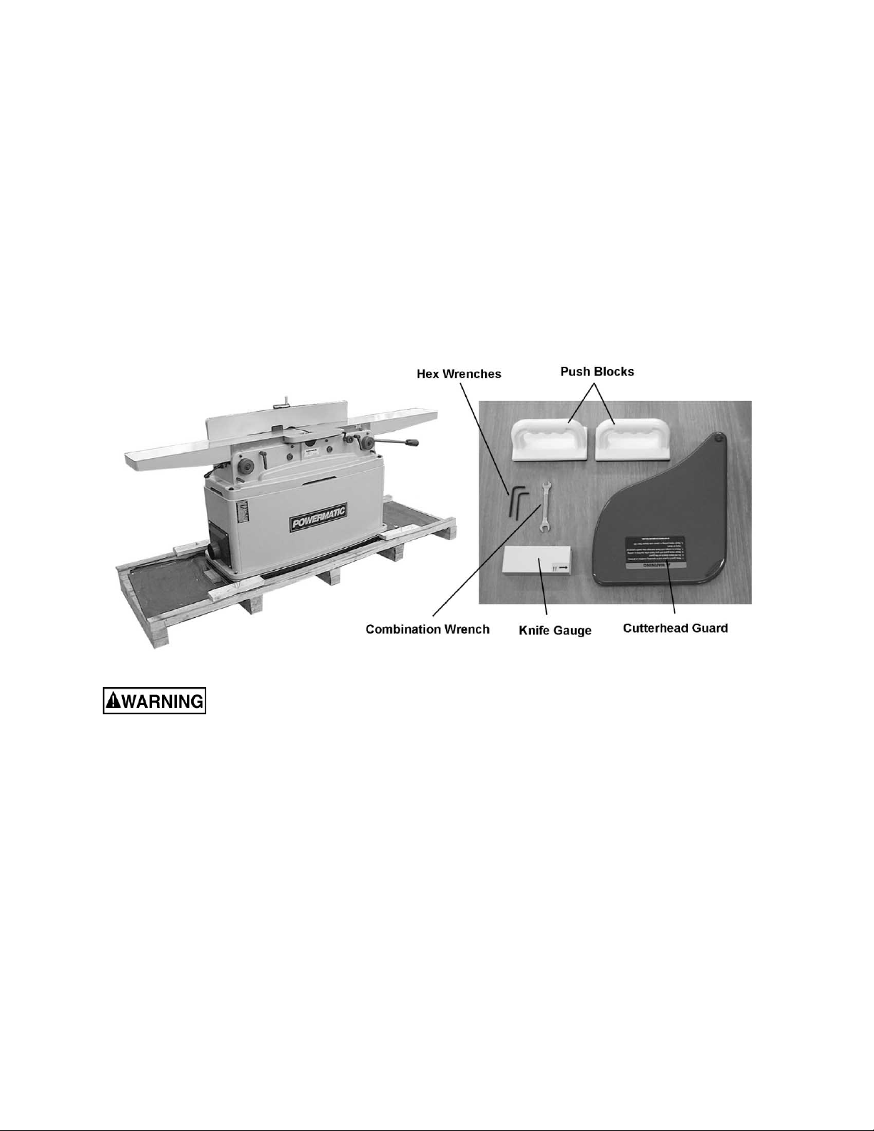
Contents of the Shipping Container
1 Jointer
1 Cutterhead guard
2 Push blocks
1 Combination wrench (8-10 mm)
2 Hex wrenches (3mm and 5 mm)
1 Aluminum k nife gauge
1 Owner's Manual
1 Warranty Card
Read and understand the ent ire contents o f this manual before attempting set-up
or operation! Failure t o co mpl y may cause seri ous injury.
8
Page 9
Installation and Assembly
Tools required for assembly
Forklift or hoist with straps/slings
14mm (or 9/16”) wrench or socket
Cross-point (Phillips) screwdriver
3mm and 5mm hex wrenches (provi ded)
1. Remove any boards or straps that secure
the Jointer to the pallet, and remove
protective wrapping.
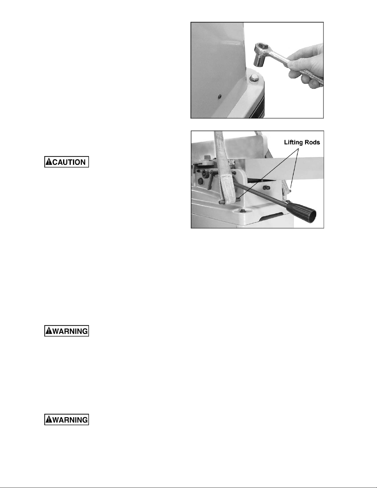
2. Use a 14mm (or 9/16”) wrench to remove
the four l ag screws at t he base of the stand
which helped secure the machine to the
pallet. One of these screws is shown in
Figure 1.
The Joint er should be raised
by straps placed arou nd the four lifting rods
(see Figure 2). Do NOT lift the machine
directly beneath the infeed and outfeed
tables, as this can cause misal ig nment of the
tables.
Figure 1
3. Pull the four lifting rods out as far as they
will go and run the straps around the rods
as shown in Figure 2. Using a forklift or
hoist, lift t he machine off the pallet and into
its desired location. When the straps are
removed, push the lift ing rods back in.
4. The Jointer should be locat ed in a dry ar ea,
on a sturdy fl oor, and with suff icient light ing
and ventilation. Leave plenty of space
around the machine for operations and
routine maintenance work.
5. If desired, the Jointer can be further
stabilized by securing it to the floor, using
lag screws through the four holes at the
base of the stand.
The jointer should be
disconnect ed from the power sou rce during
assembly procedures.
6. Exposed m etal areas of the Joi nt er, such as
the table and fence surfaces, have been
factory coated with a protectant. This can be
removed with a soft cloth dampened with
kerosene or mineral spirits. Do not use an
abrasive pad. Do not let solvent contact
plastic or rubber parts as it may damage
them.
Use caution when cleaning
around cut terhead. The knives are ext remely
sharp.
Figure 2
(straps not included)
9
Page 10
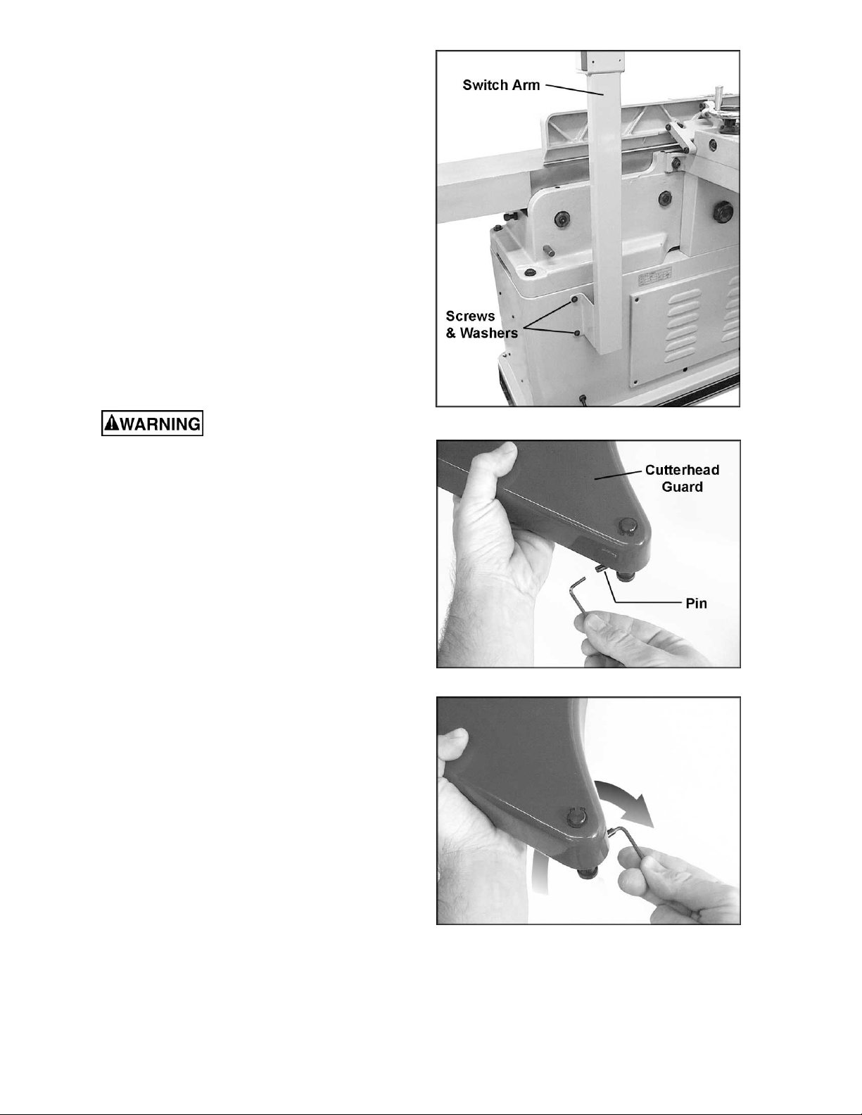
Installing Switch Arm
1. The switch arm was shipped in horizontal
position. Loosen and remove t he four socket
head cap screws and flat washers on the
bracket of the switch ar m (Figure 3) with a
5mm hex wrench. Hol d on t o the switch ar m
while doing this, to prevent the arm from
falling.
2. Place the switch arm in vertical positi on, as
shown in Fi gure 3, and align the f our holes
in the bracket with the four holes in the
jointer stand.
3. Re-insert the four socket head cap screws
with the four flat washers, as shown in
Figure 3.
4. Firmly tighten the four socket head cap
screws with the hex wrench.
Installing Cutterhead Guard
Jointer knives are extremely
sharp. Use caution when working with or
around the cutterh ead.
The cutterhead guard has a spring tension
mechanism which must be properly tensioned
when installing the cutterhead guard on the
machine.
To install the cutterhead guard:
1. Insert a small hex wrench, or similar obj ect,
into the pin on t he guard tension mec hanism
(Figure 4).
2. Twist the hex wrench and pi n clockwise, a s
shown in Figure 5, and hold them there.
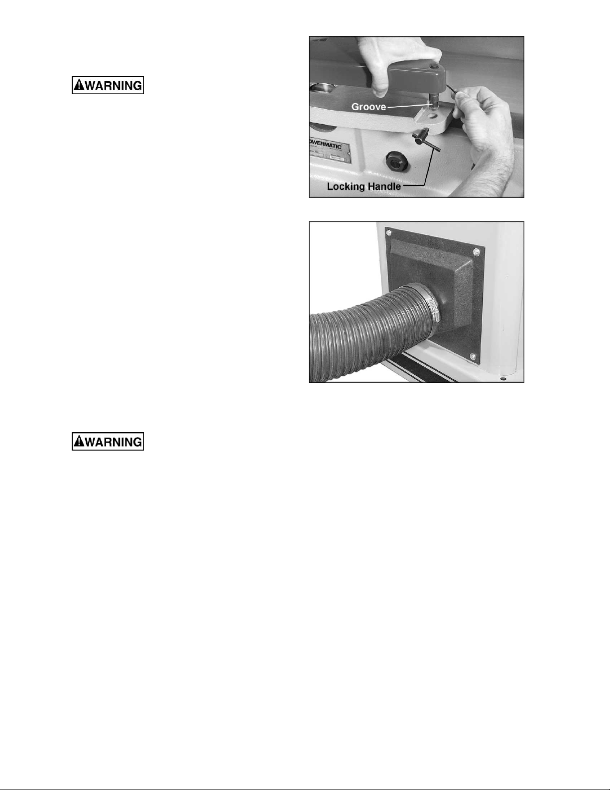
3. Lower t he shaft of the guard int o the hole on
the jointer’s rabbeting ledge. See Figure 6.
The guard should be lowered into the hole
far enough that the groove in the guard’s
shaft will mate with the shaft of the locking
handle (Figure 6) .
4. After the guard has been inserted into the
hole, let go of the guard with your left hand the guard will swing toward the fence.
Figure 3
Figure 4
5. Completely tighten the locking handle
(Figure 6), whil e continuing to hold the hex
wrench and pin with your right hand.
6. When the guard is secured, rem ove the hex
wrench from the pin. Slightly loosen the
locking handl e (Figure 6) unti l the pin snaps
back against the r abbeting ledge.
7. Re-t ighten the locki ng handle ( Figure 6).
Figure 5
10
Page 11
The cutterhead guard should now have
sufficient spring tension. Test i t by swingi ng the
guard away from the fenc e and then releasing it.
The guard mu st always have
enough spring tension to cover the unused
part of the cutterhead during the cutting
operation, and to swing back to contact the
fence when the workpiece has cleared the
area.
If more spring tension on the guard is desired,
follow the abov e procedure with this exc eption:
tighten the locking handle without allowing the
pin to snap back to the rabbeting ledge. The
farther cl ockwise the pin i s situated, t he greater
will be the spring tension.
Dust Collection
It is strongly recomm ended that a dust collection
system (not provided) be connected to the
jointer. It will help keep your shop clean, and
reduce the ri sk of heal th problems due to wood
dust. The dust collector should have sufficient
capacity for this size jointer.
Figure 6
Connect the dust collection hose to the 4”
diameter dust por t on the jointer (Fi gure 7) and
secure it with a hose clamp or duct tape.
NOTE: Dryer v ent hose is not acceptabl e for this
purpose.
Grounding Instructions
Electrical connections must
be made by a qualified electrician in
compliance with all relevant codes. This
machine must be properly grounded to help
prevent electrical shock and possible fatal
injury.
This mac hine m ust be grounded. I n the event of
a malfuncti on or break down, groundi ng prov i des
a path of least resi stance f or electric current to
reduce the ri sk of el ectri c shock.
Improper connection of the equipmentgrounding conductor can result in a risk of
electric shock. The conductor with insulation
having an outer surface that is green with or
without yellow stripes, is the equipmentgrounding conductor. If repair or replacement of
the electric cord or plug is necessary, do not
connect the equi pment-grounding c onduc tor to a
live terminal.
Check with a qualified electrician or service
personnel if the grounding instructions are not
completely understood, or if in doubt as to
whether the tool is properly grounded.
Figure 7
(hose and clamp not prov ided)
11
Page 12

Use only three wire extension cords that have
three-prong grounding plugs and three-pole
receptacles that accept the tool’s plug.
Repair or replace a damaged or worn cord
immediately.
Make sure the voltage of your power supply
matches the specif ications on the m otor plate of
the Jointer.
Extens ion co rds
The use of an extension cord is not
recommended f or the PJ882 Joint er. But if one
is necessary, make sure the cord rating is
suitable for the amperage listed on the
machine’s motor plate. An undersized cord will
cause a drop in line volt age resulting in loss of
power and overheating.
Use the chart in Fi gure 8 as a general guide in
choosing the cor rect size cord. If in doubt, use
the next heavi er gauge. The smaller the gauge
number, the heavier the cord.
Recommended Gauges (AWG) of Extension Cords
Extension Cord Length *
25
50
75
100
150
Amps
< 5 16 16 16 14 12 12
5 to 8 16 16 14 12 10 NR
8 to 12 14 14 12 10 NR NR
12 to 15 12 12 10 10 NR NR
15 to 20 10 10 10 NR NR NR
21 to 30 10 NR NR NR NR NR
feet
feet
feet
feet
feet
200
feet
230 Volt, Single Phase Operation
As receiv ed from the f actory, the single-phase
model of the PJ-882 Jointer i s designed to run
on 230 volt power only.
You may either connect a UL/CSA listed 230V
plug (similiar to the one shown in Figure 9) or
“hard-wire” the machine directly to a control
panel. If hard-wired to a panel, make sure a
disconnect is available for the operator. The
Jointer must comply with all local and national
codes after being wir ed.
If the Joi nter i s to be hard- wired, m ake sure the
fuses have been r emoved or the breakers hav e
been tripped in the circuit to which the Jointer
will be connected. Place a warning placard on
the fuse holder or circuit breaker to prevent it
being turned on while the machine is being
wired.
The Jointer with a 230 volt plug should onl y be
connected to an outlet having the same
configurati on. No adapter is av ailable or should
be used with the 230 volt pl ug.
Three Phase Operation
The three-phase model i s factory wired f or 230
volt, but can be converted to 460 volt if so
desired (see “Co nverti ng From 230 Volt to 460
Volt”).
*based on li miting th e lin e vol tage drop to 5V at 15 0% of th e
rated amp eres.
NR: Not Recommended.
Figure 8
Figure 9
You may either connect a UL/CSA listed plug, or
“hard-wire” the machine directly to a control
panel. If hard-wired to a panel, make sure a
disconnect i s available for the operator.
12
Page 13
If you are hard- wiri ng the Joi nt er, m ake sure the
fuses have been r emoved or the breakers hav e
been tripped in the circuit to which the Jointer
will be connected, and place a warni ng placard
on the fuse holder or ci rcuit br eaker t o prevent it
being turned on until wir ing is complete.
Converting from 230 Volt to 460 Volt
(Three Phas e Only)
Refer to the diagr am on page 46 for connecting
the motor leads for 460 volt power. If using a
plug, it must be a proper UL/CSA listed plug
suitable f or 460 volt operati on. T he Joi nter m ust
comply with all local and national codes after
being wired.
Three-Ph ase Test Run
On the three-phase unit, after wiring has been
completed, you should check that the wires
have been connected pr operly:
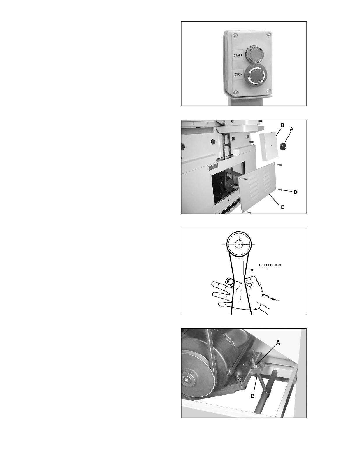
1. Connect machine to power source and
press the start butt on, shown in Figure 10.
(See “Operating Controls” on page 24 for
further inf ormation on the control switch.)
Figure 10
2. The cutterhead should rotate clockwise as
viewed from the front of the mac hine. If the
cutterhead rotation is incorrect, press the
stop button (Figure 10) and disconnect
machine from power.
3. Swit ch any two of the three wires at "R,S,T ".
4. Reconnect machine to power source.
Adjustments
Drive Belt Tension
To check or adjust t he drive belt tension:
1. Unscrew the knob (A, Figure 11) and
remove the belt guar d ( B, Figure 11) .
2. Remove the rear panel (C, Figure 11) by
unscrewing the four flat head screws (D,
Figure 11) with a cr oss-point screwdriver.
3. Proper drive belt tension is achiev ed when
there is a small amount of deflecti on in the
drive belt midway between the pulleys,
when using moderate finger pressure
(Figure 12).
Figure 11
Figure 12
4. To increase the tension on the drive belt,
loosen the lower hex nut (B, Fi gure 13) with
a 17mm wrench, and ti ghten the top hex nut
(A, Figure 13) . When finished, ti ghten lower
hex nut (B, Figure 13).
5. Re-install rear panel and belt guard.
Figure 13
13
Page 14
NOTE: After operating the machine for a short
time, the drive belt tension should be rechecked, as the new drive belt may stretch
slightly duri ng the “breaking-in” period.
Drive Belt Replacement
1. Unscrew the knob (A, Figure 11) and
remove the belt guar d ( B, Figure 11) .
2. Remove the rear panel (C, Figure 11) by
removing the four flat head screws with a
cross-point screwdriver.
3. On the mot or base pl ate, loosen the top hex
nut (A, Figure 13), and lift up on the motor to
create slack in the drive belt. Remove the
drive belt from both pulleys.
4. Install the new drive belt around top and
bottom pulleys, and tension it appropriately
(see “Drive Belt Tension”).
5. Re-install rear panel and belt guard (Fi gure
11).
Fence Movement
The fence can be moved forward or backward
across the widt h of the table. It also tilts up to 45
degrees forward and backward, and contains
positive stops at bot h the se angl e s, as well as a
positive stop at 90 degrees.
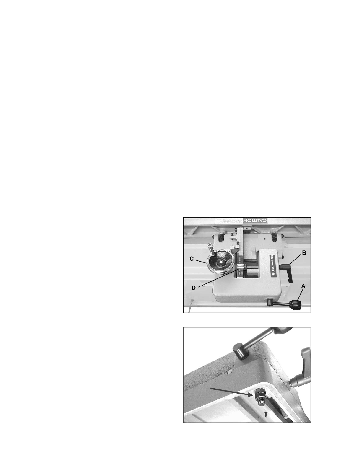
To slide fence forward or backward:
1. Loosen locking handle (A, Figure 14).
2. Push the entire fence assembly to the
desired posit ion, and tighten loc king handle
(A, Figure 14). A plastic buffer piece is
mounted to t he fr ont of t he fence to prev ent
scratching the table when the fence is
moved.
NOTE: If the lock handle (A, Figure 14) i s in an
inconvenient position, it can be adjusted.
Loosen the two hex nuts underneath the slide
bracket (Figure 15). Flip the handle to the
desired posit ion, and re-ti ghten t he hex nut s. Do
not overti ghten the hex nuts, as thi s can make
the fence difficult to move on the slide bracket.
To tilt fence forward:
The fence can be tilted forward to any angle
down to 45 degrees.
1. Loosen locking handle (B, Figure 14).
2. Rotate handwheel (C, Figure 14) until the
desired angle i s indicated on the scale (D,
Figure 14). Or you can place your beveled
workpiece on the table and against the
fence, and rotate t he handwheel (C, Fi gure
14) until the angle of the f ence matches the
bevel of your workpiec e.
Figure 14
Figure 15
14
Page 15
3. Tighten locking handle (B, Figure 14).
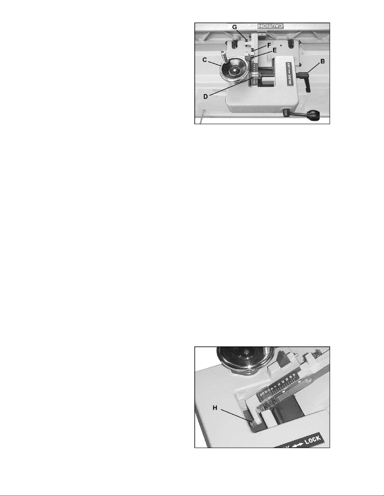
To tilt fence backw ard:
The fence can be tilt ed back ward up to 45° (t hat
is, for a total angle of 135° from table surface).
1. Loosen locking handle (B, Figure 16).
2. Flip the 90° stop bl ock (E, Figure 16) out of
the way.
3. Rotate handwheel (C, Figure 16) until the
desired angle i s indicated on the scale (D,
Figure 16). Or you can place your beveled
workpiece on the table and against the
fence, and rotate t he handwheel (C, Fi gure
16) until the angle of the f ence matches the
bevel of your workpiec e.
4. Tighten locking handle (B, Figure 16).
IMPORTANT: When the tilted operation is
finished and the f ence is ret urned to 90°, do not
forget to flip the 90° stop block (F, Figure 16)
back to its origi nal posi tion.
Figure 16
Fence Stops
Periodic ally check the 90° and 45° til t accuracy
of the fence with an angle measuring device,
such as an adjustable square or machinist’s
protractor. If adjustments are necessary,
proceed as follows:
Setting the 90° Stop
1. The 90° stop is contr olled by the screw (F,
Figure 16) and the stop block (E, Figure 16).
2. Loosen the locking handle (B, Figure 16)
and loosen the hex nut on the screw (F,
Figure 16).
3. Set your angle measuring device to 90
degrees, and place it on the table and
against the fence.
4. Move t he fence until it fit s flush against the
angle measuri ng device. Turn t he screw (F,
Figure 16) until t he screw contacts the stop
block (E, Figure 16).
5. Ti ghten the hex nut on the screw (F, Figure
16) and the lock handl e (B, Figure 16) .
Setting the 45° Forward Sto p
1. The 45° forward stop is controlled by the
screw (H, Figure 17).
2. Loosen the locking handle (B, Figure 16)
and loosen the hex nut on the screw (H,
Figure 17).
3. Set your angle measuring device at 45°.
Place it on t he table and against the fence,
and tilt t he fence until it is flush against t he
45° angle.
Figure 17
15
Page 16

4. Rotate the screw (H, Figure 17) until it
contacts the casting in front of it.
5. Tighten t he hex nut on the scre w (H, Fi gure
17) and tighten locking handle (B, Figure
16).
Setting the 45° Backward Stop
1. The 45° backward stop is cont rolled by the
screw (G, Figure 18), which will contact the
back of the fence when the fence is tilted
backward.
2. Fli p the stop block (E, Figur e 18) out of t he
way.
3. Loosen the locking handle (B, Figure 18)
and loosen the hex nut on the screw (G,
Figure 18).
4. Tilt the fence backward. Set your angle
measuring device at 135° and place it on
the table and against the fence.
5. If necessary, turn the screw (G, Figur e 18),
until the fence lies flush against the angle
measuring devic e.
6. Re-tighten the hex nut on the screw (G,
Figure 18) and tighten locking handle (B,
Figure 18).
Fence Removal
To remove the fence assembly from the
machine, r emove the two hex nuts and one flat
washer that secure it to the slide bracket (see
Figure 15). Lift the fence strai ght up and off the
Jointer.
When re-installing the fence assembly, make
sure the cutout in t he fence assembly sits ov er
the key in the slide br ac k et.
Figure 18
Locking Handles
All locking handles of the type shown in B,
Figure 18, c an be rotated if they are i n the way
of other m ac hi ne par ts. Simply lif t straight out on
the locking handle and rotate it, then release,
making sure it seats properly.
Table and Knife Adjustments
For accurat e jointing, at least three t hings must
be true:
1. Infeed and outf eed tables must be parall el,
or “coplanar” .
16
Page 17

2. Knives m ust be set i n the c utt erhead so that
P
s
the highest point of thei r arc is level wit h the
the outfeed table.
3. Knives must be parallel with the outfeed
table across the entire length of the knives.
These alignments are explained below.
Setting Tables Parallel
For optimum performance of the jointer, the
infeed and outf eed tables must be parall el frontto-back with eac h other. If they are not paral lel,
the finished workpiece may have a slight taper
across its width or length.
The tables hav e been set parall el at the f actory,
but they should be double-checked by the
operator. Also, as the machine receives use,
this parallel setting should be checked
occasionally and adjusted if necessary.
The following procedure uses a steel straight
edge to set the t ables, which should be accurate
enough for most pur poses.
This procedure demonstrates how to set the
parallelism of the outfeed table; the procedure
for the infeed tabl e wil l be identical.
1. Di sconnect jointer from power source.
2. Remove the cutterhead guar d by loosening
the locking handl e (see Figure 6) an d lifti ng
the guard shaft out of the hol e.
3. Slide the fence assembly back as far as it
will go, or remove it from the machine
entirely.
4. Loosen the locking handle on the outfeed
table (see A, Figure 23). Use the lifting
handle (B, Figure 23) to raise the outfeed
table higher than the cutterhead.
lace a straight edge ac ross the front of the
5.
outfeed tabl e and extending ov er the infeed
table. See Figur e 19.
6. Raise the infeed table until it contacts the
traight edge. To raise the infeed table,
loosen the locki ng handle ( see A, Figure 28)
and lift the adjustment arm (B, Figure 28).
When it contacts the straight edge, tighten
the locking handle (A, Figure 28).
7. The straight edge should lie level across
both tables. Move the straight edge to the
back of the outfeed table, and perf orm the
same test. See Figure 20.
8. If the straight edge does not lie level, the
front or back of the t able must be adjusted
to make the tables paral lel with each other.
Proceed as follows.
Figure 19
Figure 20
17
Page 18

9. Each table has four cam adjustment
devices; two in front and two in back.
NOTE: On the front of the Jointer, the two
outside cams are concealed by the hubs.
You must remove the hub to expose the
cam adjustment dev ice. Remove the socket
head cap screw and flat washer at the
center with a 6mm hex wrench, and loosen
the two setscrews in the hub (Figure 21
shows one of the two set scre w holes). Pull
the hub straight out to expose the cam
adjustment device.
10. At the area of the table where the
adjustment must be made, pry out the cap
(A, Figure 22) fr om the hole.
11. T here are two set screws in the hol e. Insert
a 4mm hex wrench (B, Figure 22) into the
hole and loosen the upper set screw by
turning the hex wrench counterclockwise.
Remove the upper set screw fr om the hole.
12. Loos en the lower set screw (do not rem ove
it) by turning c ounterclockwise with the hex
wrench.
13. Turn the hex nut (C, Fi gur e 22) with a 1-1/4"
wrench. T his adjustment i s sensitive and
should be made in small increment s.
NOTE: The rotation is different for left and
right hex nuts; the right hex nut being turned
in Figure 22 will be turned clockwise to raise
that area of the tabl e, or c ounterclockwise to
lower that area of the table. The left hex nut
shown in Fi gure 22 would be rotated i n the
opposite manner.
14. Use the straight edge upon the table and
across the cutterhead to check the
adjustment until the tabl e is parallel wit h the
cutterhead.
15. When the adjustment is satisfactory, with
the tables now parallel to the cutterhead,
tighten the lower set screw with the hex
wrench (B, Figure 22).
16. Insert and tighten the upper set screw.
17. Re-insert the cap (A, Figure 22) to keep
dust and debris out of t he hole.
Setting Knives at Correct Height and Parallel To Outfeed Table
Figure 21
Figure 22
(back of outfeed table shown)
For accurate jointing, the outfeed table surface
must be level with the kniv es at the hi gh point of
their arc. Al so, the knives must be parall el with
the outf eed table along the enti re length of the
knives.
18
Page 19

When you receive the jointer, the knives have
been pre-set at t he factor y. However, the height
and parallelism of the knives with the outfeed
table should be checked, and any needed
adjustment s made, before put ting the j ointer into
operation.
Proceed as follows:
1. Di sconnect jointer from power source.
2. Place a straight edge upon the outfeed table
and extending over the center of the
cutterhead as shown in Figures 23 and 24.
3. Rotate the cutterhead, using the belt or
pulley, until one k nife is at its highest point.
Do not grab the cutterhead it self to rotate it.
4. Lower the outfeed table until the straight
edge contacts the knif e, as shown in Figure
24. Using the driv e belt, r ock the cutterhead
slightly t o make sure t he apex of the knif e is
contacti ng the str aight edge.
5. Lock the outfeed table at that setting by
tightening t he l oc ki ng handle (A, Figure 23).
Figure 23
The importance of the knives being level with
the outfeed tabl e are shown by these ex amples
of incorrect settings:
If the outfeed table is too high, the finished
surface of the workpiece will be curved. See
Figure 25.
If the outf eed table i s too l ow, the work will have
a gouge, or snipe, at the end of the cut. See
Figure 26.
Figure 24
Figure 25
Figure 26
19
Page 20

Figure 27 illustrates the correct setting of
outfeed table level with the knives. The
workpiece will rest firmly on both tables with no
open space under the finished cut.
The outfeed table has now been locked at a
standard height, l ev el with the arc of t he knives.
NOTE: After the outfeed table has been set at
the correct height, it should not be changed
except for special operations or after replacing
knives.
Further fi ne adjustments will now be achieved by
adjusting the k nives in the cutt erhead. Proceed
as follows.
Figure 27
Jointer knives are extremely
sharp; use cau tion and p roceed slowly wh en
setting them.
6. Lower the infeed table out of the way, by
loosening the l ocking handl e (A, Figure 28)
and pushing down on the adjustment arm
(B, Figure 28).
7. An aluminum knif e setting gauge, shown in
Figure 29, is provi ded with the jointer. If you
require very fine tolerances when setting the
knives, a knife setting gauge with a dial
readout can be purchased (see “Optional
Accessories” on page 32). The provided
aluminum gauge should, however, be
accurate enough for most woodworking
needs.
8. Place the provided knife setting gauge at
the back of the outfeed table (toward the
fence support si de) and extending over the
cutterhead as shown i n Fi gure 29. Place t he
gauge so that the right mark lines up with
the edge of the outfeed t able, as shown.
9. Rotate the cutterhead clockwise (by using
the pulley). If table and knives are set
correctly, the knife will contac t the al umi num
gauge and move the gauge until the left
mark now lines up with the edge of the
outfeed tabl e, as shown in Fi gur e 30.
Figure 28
Figure 29
20
Page 21

10. Plac e the alumi num knife gauge at t he fr ont
of the outfeed table (toward the rabbet
ledge) and repeat the process.
11. This test should be performed on all three
knives in the cutter head, using the provi ded
gauge.
12. If any knife is either too high or too low at
one of its ends to corr ectly move the gauge
as described abov e, then the height and/or
parallelism of that knife in the cutterhead
needs to be adjusted. Proceed as follows.
13. Slightly loosen the five gib screws (see
Figure 31) with an 8mm wrench. (NOTE:
The springs below the knife will cause the
knife to ris e .)
14. Turn the jack screw(s) with a hex wrench;
clockwise to l ower the setting of the knif e i n
the cutterhead, counterclockwise to raise
the setting of the knife.
15. Use the edge of a board to push the knife
back down so that it is fl ush against the j ack
screws. See Figure 32. Tighten the gib
screws only enough to keep the knife in
position in the cutterhead. Do not fully
tighten.
16. Check t he height of t he knif e agai n by usi ng
the gauge at front and back of the outfeed
table. Make further adjustments to the jack
screw(s) as needed.
17. Repeat this process for each of the other
two knives in turn. Do not fully tighten gib
screws, only tighten them enough to keep
the knife in positi on.
18. For best results, knives should be set at
approximately .015" above the cutterhead.
Knife height shoul d not vary more t han .002.003" across the length of the cutterhead. All
three knives must be set at equal height in
the cutterhead and parallel to the outfeed
table across thei r length.
Figure 30
Figure 31
19. Aft er all three kniv es are po sit ioned pr operl y
in the cutterhead and m ade snug, continue
tightening the gib screws. The gib screws
should be tightened in increments, to
prevent any distortion to the cutterhead or
buckling of knives. Begin tightening t he gib
screws a lit tle more on one knif e. Star t with
the center screw and work your way to the
ends. Do not fully tighten yet.
20. Rotate the cutterhead to the other two
knives in turn. Repeat step 20 for each
knife.
Figure 32
21
Page 22

21. The tightening process should continue at
least two more times, each time tightening
the gib screws furt her on all three knives in
turn. On the third time, the gib screws
should all be firml y tight ened.
Before operating the jointer,
make sure all gib screws are firmly
tightened. A loose knife thrown from the
cutterhead can cau se severe or fatal injury.
22. After all knife adjustments are completed,
the guards and fence assembly should be
placed back on the machine before
operating.
Outfeed Table Stop Screws
The stop scre w (B, Figur e 33) limi ts the am ount
of fall of the outfeed t able. The stop screw has
been pre-set at the factory, but if future
adjustment is ever needed, simply loosen the
hex nut (A, Figure 33) and turn the screw (B,
Figure 33) as needed with a 14mm wrench.
When satisf ied, re-ti ghten t he hex nut ( A, Fi gure
33).
The screw (C, Figure 33) limits the rise of the
outfeed table. If adjustment is needed, loosen
the hex nut (D, Figur e 33) and turn the screw (C,
Figure 33) as needed with a 9mm hex wrench.
When satisfi ed, re- tight en the hex nut (D, Figur e
33).
Figure 33
Setting Infeed Table (Depth of Cut)
1. Loosen locking handle (A, Figure 34).
2. Move tabl e adjustment arm (B, Figure 34) t o
raise or lower infeed table to the desired
depth of cut , which is shown on the gauge
via the pointer (C, Fi gur e 34) .
NOTE: Do not exceed 1/8” maximum depth of
cut. For deeper cuts, make several passes.
3. Re-t ighten locking handle (A, Figure 34).
Infeed Table Depth Stop
The knob (Figure 35) controls a depth stop.
When the i nfeed table is lowered, i t will stop at
the 1/8” depth mark.
To further lower the infeed table, such as for
rabbeting operat ions, disengage the depth stop
by pulling out on the k nob, rot ati ng t he knob 90°
and then releasing i t. The i nfeed table can then
be lowered all the way.
To re-engage the depth stop, rotate the knob
90° until the knob snaps back in.
Figure 34
Figure 35
22
Page 23

Infeed Table Stop Screws
The stop screws below the infeed table have the
same function as those for the outfeed table.
See “Outfeed Table Stop Screws” for
instructions on adjustment.
Replacing Knives in the Cutterhead
Jointer knives are extremely
sharp. Use caution and p roceed slowly wh en
working with or around the cu t t erhead.
1. Di sconnect jointer from power source.
2. Remove the belt guard so that you can
rotate the cutterhead by turning the motor
pulley or by moving the drive belt. Do not
grab the cutter head itself to rotate it.
3. Remove the old knives by loosening the
square head gib screws with an 8mm
wrench. See Figure 36. The springs in the
cutterhead will raise the knife for easy
removal. Remove knife and gib.
4. Clean the gib and the knif e slot. Sandwich
the new knife and gi b toget her and drop int o
slot. Make sure t he k nife is oriented properly
in the cutterhead, as shown in Figure 36.
Figure 36
IMPORTANT: T o position the knives for rabbet
cuts, take a shop scale with 1/32” graduations
and place it against the end of the cutterhead.
Slide the knif e out until it i s at the 1/ 32” m ark on
the scale; that is, the knife will now be 1/32”
beyond the edge of the cutterhead. The gib
should remai n in normal posit ion, even with the
edge of the cutterhead. See Figure 37. This
adjustment will ensure that the knife clears the
end of the gib and cutterhead, and has good
contact with the workpiece. (See under
“Operation” for further i nformation on rabbeting
procedures.)
5. The height and paral lelism of the k nife in the
slot, both for rabbeting and normal jointer
work, must now be set properly, to ensure
correct operation as well as minimize the
hazard of kic kback. Refer to “S etting Knives
at Correct Height and Parallel to Outfeed
Table” on page 18 for information on
adjustment and tightening procedures for
the knives.
Before starting the jointer,
make sure all gib screws are firmly
tightened. A loose knife thrown from the
cutterhead can cau se severe or fatal injury.
Figure 37
23
Page 24

Eliminating “Play” in Tables
There are four set screws at the front of the
jointer – two on the outfeed table and t wo on the
infeed table – that will allow you to prevent
“play” in the tables. (Figure 38 shows a set
screw for the outfeed table.)
After a period of use, the copper tip (see item
#27, page 37) which is attached to the end of
the set screw (A, Fi gure 38) may becom e l oose.
Resolve this as follows.
1. Loosen the hex nut (B, Figure 38) with a
14mm wrench.
2. Tight en the set screw (A, F igure 38) with a
5mm hex wrench. Do not over tighten the set
screw, as it may prevent the table from
being raised and l owered easily.
3. Tighten hex nut (B, Figure 38).
4. Repeat for the other set screws as needed.
NOTE: The outfeed table is pre-set at the
factory tighter than the infeed table. If you find
the outf eed table diffi cult t o move with t he lifti ng
handle, loosen the two set screws on the
outfeed tabl e, as j ust described.
Operating Controls
Press the start switch, shown in Figure 39, to
begin rotation of the cutter head. T he stop butt on
is a mushroom style button which i s conveni ent
for "emergency " shut-downs.
After being pushed, the stop button remains
engaged. To re-start the Jointer, twist the stop
button clockwise until it pops back out.
Figure 38
Operation
NOTE: If y ou are inexperienced at jointing, use
scrap pieces of lumber t o c hec k settings and get
the feel of operati ons before att empting regul ar
work.
Stabilize l ong workpieces by using a n assistant ,
or roller stands set level with the outfeed or
infeed table surf ac e.
The fence should be adjusted to create
minimum exposure t o the cutterhead during the
jointing operation.
Check the following before operating the j ointer:
1. Outfeed table must be set level with the hi gh
point of the knives.
2. Fence adjusted for minimum exposure of
cutterhead, and locked at desired angle.
Figure 39
24
Page 25

3. The cutterhead guar d must be in place and
operating proper ly (except when rabbeting) .
4. Infeed table set for desir ed depth of cut.
5. Stand away from the cutterhead and turn
the machine on for a f ew moments. Listen
for any odd noises, rubbi ngs, vi brati ons, etc.
Correct such problems before attempting
operations on the jointer.
6. Carefully check your workpiece for knots,
holes, staples or any foreign material that
might damage knives or pose a risk of
kickback. A lso check the workpiece for gr ain
orientation.
Hand Placement
At the start of the cut, the left hand holds the
workpiece firmly against the infeed table and
fence while the ri ght hand pushes the workpi ece
in a smooth, even motion t oward the cutterhead.
After the c ut is under way, the new surface rests
firmly on the outfeed table. The left hand is
transferred to the outfeed side and presses
down on this part of t he workpiece, at the same
time maintaining flat c ontact with the fence. The
right hand presses the workpiece forward and
before the right hand reaches the cutterhead it
should be moved to the work on the outfeed
table. Never pass hands directly over the
cutterhead.
Surfacing
Always use a hold down or
push block when surfaci ng stock.
Jointing the f ace of stock, or surf acing, i s shown
in Figure 40. Adjust the infeed tabl e for depth of
cut. Cuts of approximately 1/16” at a time are
recommended, as this allows better control over
the material being surfaced. More passes can
then be made to reach the desir ed depth.
Figure 40
Edge Jointing
This is the most common operation for the
jointer. Set fence square with the t able. Depth of
cut should be the m inimum requi red to obtain a
straight edge. Do not make cuts deeper than
1/8" in a single pass. Hol d the best face of the
workpiece firmly against the fence throughout
the feed. See Figure 41.
Figure 41
25
Page 26

Rabbeting
A rabbet cut requires
removal of the guard. Use extreme caution
and keep hands cl ear of cutterhead. Alw ays
re-install guard immediately after rabbeting
operation is completed.
A rabbet is a groove cut along the edge of a
board. See Figure 42. The width and thick ness
of the wood to be rabbeted depends upon the
width and length of the rabbet. Ho wever, never
rabbet a piece of wood less than 12” l ong.
Use push blocks to rabbet cut whenever
possible. The rabbeting capacity is 1/2”.
1. Di sconnect jointer from power source.
2. Set fence for desired width of rabbet .
3. Check width of the rabbet by measuring t he
distance from the end of a knife in the
cutterhead to t he fence. NOTE: The kniv es
must be extended beyond t he cut ter head by
1/32”. (see “Replacing Knives in the
Cutterhead” for this procedure).
Figure 42
4. Re-connect power. It is easier and safer t o
take a series of shallow cuts. Lower the
infeed table 1/32” at a time and make
successive cuts until the desired depth of
rabbet has been obtained. See Figure 42.
Jointing Short or Thin Work
When jointing short or thin work pieces, use a
push block to elim inate all danger to t he hands.
Two push blocks are shipped with your jointer.
You can also mak e your own easily from scrap
material. Ex am ples are shown in Figure 43.
Jointing Warped Surfaces
If the wood to be jointed is cupped or bowed,
place the concave side down, and take light cuts
until the surfac e i s flat.
Avoid forcing such material down against the
table – excessive pressure will spring it while
passing the kniv es, and it will spring back and
remain curv ed aft er the c ut is completed.
Beveling
To cut a bevel, lock the fence at the required
angle and run the work piece acros s the knives
while keeping it firmly against the fence and
tables. Several passes may be necessary to
achieve the desi r ed r esul t.
Figure 43
26
Page 27

Although the fence may be
tilted in or out for a bevel cut, it is
recommended for safety reasons that the
fence be tilted in toward the operator,
making a cradled cut.
Direction of Grain
Avoid feeding work into the jointer against the
grain. Thi s may r esult in c hipped and spl i ntered
edges. See Figure 44. Feed with the grain to
obtain a smooth surfac e, as shown in Figure 45.
Skewing (Shear Cutting)
When edging or facing material such as burl or
birds-eye maple, it is not unusual to deface or
mar the surface being finished. This is caused
by the cutterhead kniv es at tim es cutti ng against
the grain. In order to prevent the defacing or
marring of this type wood, it is necessary to
skew the material being worked so that it
crosses the knives at an angle.
The fence will all ow for this type of cut:
Figure 44
Figure 45
1. Release the fenc e locking handl e (A, Figure
46) and remove the two hex nuts and
washer (B, Figure 46) holding the fence to
the slide bracket. Remove the fence
assembly.
2. Remove the key (C, Figure 46) from the
fence support. If necessary, use a flat head
screwdriv er to pry up one end of the key .
3. Replace the f ence assembly at the desi red
angle across t he cut terhead. See F igur e 47.
Secure the fence to the slide bracket with
the hex nuts and washer (B, Figure 46),
then tighten the fence locking handle (A,
Figure 46).
NOTE: When placing the fence assembly back
into normal position, be sure to first install the
key into its slot.
Figure 46
27
Page 28

Maintenance
t
Disconnect machine from
power source before doing any
maintenance. Failure to comply may cause
serious injury.
The table and fence surfaces must be kept
clean and free of rust for best results. Some
users apply a thin coat of paste wax. Avoid
waxes or protectiv e sprays that contain si licone,
as this can transf er to the workpiece and make it
difficult for later finishes to adhere to the wood.
Another opti on is talcum powder appli ed with a
blackboard eraser rubbed in vigorously once a
week; this will fill casting pores and form a
moisture barrier. This method provides a table
top that is slick and all ows rust rings to be easi ly
wiped from the surface. Important also is the
fact that talcum powder will not stain wood or
mar finishes as some ot her pr oduc ts.
Gum and pitch which collect on the knives
cause excessiv e friction as the work cont inues,
resulting in overheating of the knives, less
efficient cutting, and consequent reduc tion in t he
life of t he kniv es. Use ov en cl eaner or “gum and
pitch remover” to wipe this off the knives. Use
caution when working around knives!
Figure 47
(skewing t he fence)
The bearings in the cutterhead are sealed for life
and do not require lubri c ation.
The fence assem bly should sli de easil y ov er t he
slide bracket . Keep the slide bracket, shown in
Figure 48, l ubricated with a good quality multipurpose grease. Do not get gr ease on the drive
belt.
Do not place he avy objec ts on the tables, or use
the jointer as a storage table.
Sharpening Knives
Knives should be kept sharp. Thi s will cont ribut e
to better stock finish, longer machine life, and
safer operation.
A jointer knife hone provides a simple way to
sharpen kniv es. Hones are avail able from many
woodworking supply stores. Carefully read any
instructions that accompany the hone.
Use caution and proceed
slowly when sharpening knives. Disconnect
jointer from power source, and wear
approved eye protect io n.
When finished sharpening knives, they should
be re-set level with and parallel to the outfeed
able. See “Setti ng Kniv es at Corr ect Hei ght and
Parallel to Outfeed Table” on page 18.
Figure 48
28
Page 29

Knives can usually be whetted several tim es in
the cutterhead bef ore hav ing to be rem oved and
re-ground.
TIP: If the joint er is used f requently, keeping a
spare set of knives on hand is recommended.
Extra knives (stock no. 6296046, set of 3) may
be obtained from your distributor, or by calling
customer service at 1-800-274-6848.
Cutterhead Repairs
The entire cutterhead assembly may be
removed from the Jointer for bearing
replacement or other m aintenance procedures.
Use caution when working
around sharp knives.
To remove the cutterhead, proceed as follows:
1. Di sconnect jointer from power source.
2. Remove fence assembly from jointer.
3. Lower bot h infeed and outf eed table.
4. Remove belt guard, and remove drive belt
from around cutter head pulley.
Figure 49
5. Remove knives from cutterhead.
6. Remove rabbeting ledge by loosening and
removing the two hex cap screws and
washers which secure it to the infeed table.
7. Loosen the two bolts that secure the
cutterhead to t he base; the se are accessed
through the gap below the j oint er base. See
Figures 49 and 50. Pl ace a wrench on each
of the bolt heads and turn each bol t until t he
cutterhead i s loosened.
8. Lift cutterhead strai ght up from base.
9. Remove pulley and both bearing housings.
IMPORTANT:
this should be done by qualified service
personnel. Bearings are press fitted and must
be removed or installed with an “arbor press”.
10. To re-install cutterhead, reverse the above
procedure. Before re-installing, make sure
the machine's curved seats of the base
casting are free of dirt, dust or grease, to
help ensure a tight fi t.
11. After the cutterhead has been installed,
check the infeed and outf eed table settings
in relationship to the cutterhead.
TIP: You may wish to keep an ext ra cutterhead
on hand to maintain shop produc tivity.
If the bearings need replacem ent,
Figure 50
29
Page 30

Troubleshooting – Operating Problems
Trouble Probable Cause Remedy
Finished stock i s
concave on back
end.
Finished stock i s
concave on front end.
Finished stock i s
concave in the
middle.
Ends of finished
stock are cut more
than the middle.
Chip out.
Fuzzy grain.
Knife is higher than outfeed table.
Outfeed table is higher than knife.
Both tables have t oo much end fall.
Table ends are rai sed hi gher than t he
middle.
Cutting against the grain. Cut with the grain whenev er possible.
Dull knives/i nsert s. Sharpen or replac e k niv es/inserts.
Feeding workpiec e too fast. Use slower rate of feed.
Cutting too deepl y. Make shallower cuts.
Knots, imperfections in wood.
Wood has high moistur e c ontent. Allow wood to dry or use diff er ent stock.
Dull knives. Sharpen or replac e k niv es/inserts.
Raise outfeed table until it aligns with
tip of knife. See page 19.
Lower outfeed table until it aligns with
tip of knife. See page 19.
Raise both table ends using the cam
adjustment devices. See pages 17-18.
Lower both table ends using the cam
adjustment devices. See pages 17-18.
Inspect wood closely for imperfections;
use different stock if necessary.
Cutterhead slows
while operating.
“Chatter” marks on
workpiece.
Uneven knife marks
on workpiece.
Feeding workpiec e too quickly, or
applying too much pressure to
workpiece.
Knives incorr ectly set.
Feeding workpiec e too fast.
Knives are nicked, or out of
alignment.
Feed more slowly, or appl y l ess
pressure to workpiece.
Set knives properl y usi ng pr ov ided k nife
setting gauge. Check that knife slots
are clean and free of dust or debri s.
Feed workpiece slowly and
consistently.
Replace nick ed knives; align knives
properly using k nife-setting gauge. See
page 20.
30
Page 31

Troubleshooting – Mechanical and Electrical Problems
Trouble Probable Cause Remedy
Machine will not
start/restart or
repeatedly t rips
circuit breaker or
blo ws fuses.
No incoming power.
Overload aut omatic reset has not
reset.
Jointer frequently trips.
Verify unit is connected to power, onbutton is pushed in com pletely, and
stop-button is disengaged. See page
24.
When jointer overloads on the circuit
breaker built into the motor starter, it
takes time for the machine to cool
down before restar t. Allow unit to
adequately cool bef ore attempting
restart. If pr oblem persists, check
amp setting on the mot or start er
inside the electrical enclosure.
One cause of overl oading trips which
are not electric al in nature is too
heavy a cut. The solution is to take a
lighter cut. If too deep a c ut is not t he
problem, then chec k the amp setting
on the overload rel ay . Match the full
load amps on the motor as noted on
the mo tor pl ate. If amp s etti ng is
correct then ther e is probably a loose
electric al lead. Check amp setting on
motor starter.
Building circuit breaker trips or fuse
blows.
Switch or motor f ailur e ( how to
distinguish).
Motor overheat ed.
Motor failure.
Verify that jointer is on a circuit of
correct size. If circuit size is correct,
there is probabl y a loose el ectr ic al
lead. Check amp setting on motor
starter.
If you have access to a voltmeter, you
can separate a starter f ailure from a
motor fai lu re by fi r st, verifying
incoming voltage at 220+/-20 and
second, checking the voltage
between starter and motor at 220+/-
20. If incoming voltage is incorrect,
you have a power supply problem. If
voltage between start er and m otor is
incorrect, y ou hav e a starter pr oblem.
If voltage bet ween start er and m otor
is correct, you hav e a motor pr oblem .
Clean motor of dust or debri s to allow
proper air circulation. Allow motor to
cool down before r estar ting.
If electri c mot or i s suspect, you have
two options: Have a qualified
electrician test the motor for function
or remove the motor and take it t o a
qualified elec tric motor repair shop
and have it tested.
31
Page 32

Trouble Probable Cause Remedy
Machine will not
start/restart or
repeatedly t rips
circuit breaker or
blo ws fuses.
Miswiring of the unit.
On/off switch failure.
Optional Accessories
6296046 .......... Knives (set of 3)
2230035 .......... Knife Setting Gauge
6285917 .......... Push Block
Double check to confirm all electrical
connections are cor r ec t. Refer to
appropriate wir ing diagrams on pages
44 through 46 to make any needed
corrections.
If the on/off switch is suspect, you
have two options: Hav e a qualified
electrician test the switch for function,
or purchase a new on/off switc h and
establish if that was the pr oblem on
changeout.
Replacement Parts
Replacement part s are li sted on the f ollowing page s. To order par ts or reac h our servi ce depar tment, call
1-800-274-6848 between 7:30 a.m. and 6:00 p.m. (CST), Monday through Friday. Having the Model
Number and Serial Number of your machine available when you call will allow us to serve y ou quickly and
accurately.
32
Page 33

Parts List: Cutterhead Assembly
Index No. P art No. Description Size Qty
................. PJ882-CHA............. Cutterhead Assembly (Items 1 thru 5, and 10 thru 13)..............................
1...............6296046.................. Knife.................................................................. ...................................3
2...............6296153.................. Knife Gib............................................................ ...................................3
3...............6296048.................. Key.................................................................... 5x5x25........................1
4...............BB-6204VV............. Ball Bearing....................................................... 6204-2NSE.................2
5...............PJ882-405 ..............Bearing Housing................................................ ...................................2
6...............TS-0267021............ Socket Set Screw.............................................. 1/4”-20x1/4”................2
7...............PJ882-407 ..............Pulley................................................................ ...................................1
8...............PJ882-408 ..............Bolt.................................................................... ...................................2
9...............TS-0720091............ Lock Washer......................................................3/8”.............................2
10.............6296154.................. Square Head Scr ew........................................... .................................15
11.............PJ882-411 .............. Cutterhead......................................................... ...................................1
12.............6296054.................. Spring................................................................ ...................................6
13.............TS-1513021............ Socket Flat Head Screw.....................................M5x0.8Px12...............6
14.............PJ882-414 .............. Direction Label................................................... ...................................1
15.............PJ882-415 .............. Knife Gauge ...................................................... ...................................1
33
Page 34

Parts List: Fence Assembly
Index No. P art No. Description Size Qty
................. PJ882-FA................ Fence Assembly (Index #1 thru #48).................. .....................................
1...............PJ882-101 ..............Hand Wheel....................................................... ...................................1
2...............TS-0267021............ Socket Set Screw.............................................. 1/4”-20x1/4”................3
3...............TS-0207031............ Socket Head Cap Screw.................................... 1/4”-20x5/8”................4
4...............PJ882-104 ..............Bearing Cover.................................................... ...................................1
5...............PJ882-105 ..............C-Ring............................................................... STW-12......................2
6...............PJ882-106 ..............Worm Shaft ....................................................... ...................................1
7...............BB-6001ZZ..............Ball Bearing....................................................... 6001ZZ.......................2
8...............PJ882-108 ..............Pin.....................................................................
9...............TS-0810012............ Screw................................................................ #10-24x1/4” ................2
10.............TS-0680011............ Flat Washe r....................................................... 3/16”...........................2
11.............PJ882-111 .............. Pointer............................................................... ...................................1
12.............6285945.................. Knob.................................................................. ...................................1
13.............6296069.................. Locking Shaft..................................................... ...................................1
14.............6285944.................. Handle Stud....................................................... ...................................1
15.............TS-0207021............ Socket Head Cap Screw.................................... 1/4”-20x1/2”................1
16.............6296084.................. Bolt.................................................................... ...................................1
17.............TS-0680061............ Flat Washe r....................................................... 1/2”.............................1
18.............PJ882-118 .............. Hex Nut............................................................. 1/2”-12........................2
19.............PJ882-119 .............. Locking Handle.................................................. ...................................1
20.............PJ882-120 .............. Bushing............................................................. ...................................1
21.............PJ882-121 .............. Stop Block......................................................... ...................................1
22.............PJ882-122 .............. Fence Bracket................................................... ...................................1
23.............PJ882-123 .............. Worm................................................................. ...................................1
24.............PJ882-124 .............. Retaining Ring................................................... RTW-28......................1
25.............TS-0050031............ Hex Cap Screw..................................................1/4”-20x3/4”................1
26.............PJ882-126 .............. Rack.................................................................. ...................................1
27.............PJ882-127 .............. Locking Handle Nut ........................................... ...................................1
28.............PJ882-128 .............. Locking Link ...................................................... ...................................1
29.............TS-0561011............ Hex Nut............................................................. 1/4”-20........................3
30.............TS-0050051............ Hex Cap Screw..................................................1/4”-20x1”...................2
31.............PJ882-131 .............. Safety Pla te....................................................... ...................................1
32.............TS-081F031............ Flat Head Screw................................................ 1/4”-20x1/2”................2
33.............6296070.................. Pin..................................................................... 5mmx50mm................1
34.............TS-0206021............ Socket Head Cap Screw.................................... #10-24x1/2” ................5
35.............6296073.................. Screw................................................................ ...................................1
36.............6296082.................. Fence Link......................................................... ...................................1
37.............6285942.................. Cone Point Screw.............................................. ...................................4
38.............TS-0561031............ Hex Nut............................................................. 3/8”-16........................4
39.............TS-0720071............ Lock Washer......................................................1/4”.............................2
40.............6296076.................. Bolt.................................................................... ...................................2
41.............TS-0561052............ Hex Nut............................................................. 1/2”-20........................2
42.............PJ882-142 .............. Fixed Block........................................................ ...................................1
43.............PJ882-143 .............. Fence................................................................ ...................................1
44.............PJ882-144 .............. Insert................................................................. ...................................1
45.............60B-130.................. Caution Label (Setting Knives)........................... ...................................1
46.............60B-129.................. Caution Label (Hands Clear).............................. ...................................1
47.............PJ882-147 .............. Label (Lock/ Unloc k ) .......................................... ...................................1
48.............PJ882-148 .............. Scale Label........................................................ ...................................1
49.............PJ882-333 .............. Spring Pin..........................................................
3x20.........................1
4x25.........................1
34
Page 35

Fence Assembly
35
Page 36

Parts List: Outfeed Table and Base Assembly
Index No. P art No. Description Size Qty
1...............PJ882-201 ..............Rear (Outfeed) Table......................................... ...................................1
2...............6285917.................. Push Block........................................................ ...................................2
3...............PJ882-203 ..............Shaft.................................................................. ...................................2
4...............PJ882-204 ..............Shaft.................................................................. ...................................1
5...............PJ882-205 ..............Key.................................................................... 5x5x22........................1
6...............PJ882-206 ..............Knob.................................................................. ...................................1
7...............PJ882-207 ..............Handle............................................................... ...................................1
8...............PJ882-208 ..............Table Raising Link............................................. ...................................1
9...............TS-0270031............ Socket Set Screw.............................................. 5/16”-18x3/8”............12
10.............TS-0271031............ Socket Set Screw.............................................. 3/8”-16x3/8”................2
11.............PJ882-211 .............. Shaft.................................................................. ...................................1
12.............PJ882-212 .............. Table Lip............................................................ ...................................1
13.............TS-0680011............ Flat Washe r....................................................... 3/16”...........................3
14.............TS-0810012............ Screw................................................................ #10-24x1/4” ................3
15.............PJ882-215 .............. Slide Bracket..................................................... ...................................1
16.............6296058.................. Knob.................................................................. ...................................1
17.............PJ882-217 .............. Belt Guard......................................................... ...................................1
18.............TS-0060051............ Hex Cap Screw..................................................3/8”-16x1”...................1
19.............TS-0561031............ Hex Nut............................................................. 3/8”-16........................3
20.............TS-0060121............ Hex Cap Screw..................................................3/8”-16x2-3/4” .............4
21.............TS-0680041............ Flat Washe r....................................................... 3/8”.............................4
22.............PJ882-222 .............. Plastic Washer...................................................3/8”.............................4
23.............PJ882-223 .............. Plug................................................................... ...................................4
24.............PJ882-224 .............. Socket Head Cap Screw.................................... 1/2”-12x3” ...................1
25.............PJ882-118 .............. Hex Nut............................................................. 1/2”-12........................1
26.............TS-0271101............ Socket Set Screw.............................................. 3/8”-16x1-1/4”.............2
27.............PJ882-227 .............. Copper Bushing................................................. ...................................3
28.............PJ882-228 .............. Adjustment Nut .................................................. ...................................4
29.............PJ882-229 .............. Shaft.................................................................. ...................................2
30.............PJ882-230 .............. E-Ring............................................................... ETW-12......................2
31.............TS-0208031............ Socket Head Cap Screw.................................... 5/16”-18x5/8” ..............1
32.............TS-0680031............ Flat Washe r....................................................... 5/16”...........................1
33.............PJ882-233 .............. Hub ................................................................... ...................................1
34.............PJ882-234 .............. Locking Handle.................................................. ...................................1
35.............TS-0270031............ Socket Set Screw.............................................. 5/16”-18x3/8”..............2
36.............PJ882-236 .............. Base.................................................................. ...................................1
37.............TS-0207021............ Socket Head Cap Screw.................................... 1/4”-20x1/2”................1
38.............6296088.................. Spring Pin..........................................................
39.............6296089.................. Key.................................................................... ...................................1
40.............6296042.................. W asher.............................................................. ...................................2
41.............TS-0209061............ Socket Head Cap Screw.................................... 3/8”-16x1-1/4”.............2
42.............PJ882-242 .............. Stud................................................................... ...................................1
43.............PJ882-243 .............. ID Label............................................................. 1Ph.............................1
................. PJ882-243A ............ ID Label............................................................. 3Ph.............................1
44.............6296148.................. Rivet.................................................................. ...................................2
45.............TS-0209031............ Socket Head Cap Screw.................................... 3/8”-16x3/4”................2
46.............PJ882-246 .............. Key.................................................................... 5x5x20........................2
47.............TS-0050031............ Hex Cap Screw..................................................1/4"-20x3/4”................2
48.............PJ882-248 .............. Table Raising Link............................................. ...................................1
4x14.........................1
36
Page 37

Outfeed Table and Base Assembly
37
Page 38

Parts List: Infeed Table Assembly
Index No. P art No. Description Size Qty
1...............PJ882-301 ..............Front (Infeed) Table........................................... ...................................1
2...............PJ882-302 ..............Scale Label........................................................ ...................................1
3...............PJ882-203 ..............Shaft.................................................................. ...................................2
4...............PJ882-304 ..............Shaft.................................................................. ...................................1
5...............PJ882-205 ..............Key.................................................................... 5x5x22........................1
6...............6296148.................. Rivet.................................................................. ...................................2
7...............TS-0270051............ Socket Set Screw.............................................. 5/16”-18x1/2”..............1
8...............PJ882-208 ..............Table Raising Link............................................. ...................................1
9...............TS-0270031............ Socket Set Screw.............................................. 5/16”-18x3/8”............12
10.............TS-0271031............ Socket Set Screw.............................................. 3/8”-16x3/8”................2
11.............PJ882-211 .............. Shaft.................................................................. ...................................1
12.............PJ882-212 .............. Table Lip............................................................ ...................................1
13.............TS-0680011............ Flat Washe r....................................................... 3/16”...........................3
14.............TS-0810012............ Screw................................................................ #10-24x1/4” ................3
15.............60B-273.................. Cutterhead Guard.............................................. ...................................1
16.............JSG96-223.............. Retaining Ring................................................... STW-11......................1
17.............60B-272.................. W arning Label ................................................... ...................................1
18.............TS-0060051............ Hex Cap Screw..................................................3/8”-16x1”...................3
19.............TS-0561031............ Hex Nut............................................................. 3/8”-16........................3
20.............TS-0813022............ Round Head Scr ew............................................ 1/4”-20x3/8”................1
21.............PJ882-321 .............. Pointer............................................................... ...................................1
22.............PJ882-322 .............. Lift Handle Hub.................................................. ...................................1
23.............PJ882-223 .............. Plug................................................................... ...................................4
24.............PJ882-224 .............. Socket Head Cap Screw.................................... 1/2”-12x3” ...................1
25.............PJ882-118 .............. Hex Nut............................................................. 1/2”-12........................1
26.............TS-0271101............ Socket Set Screw.............................................. 3/8”-16x1-1/4”.............2
27.............PJ882-227 .............. Copper Bushing................................................. ...................................3
28.............PJ882-228 .............. Adjustment Nut .................................................. ...................................4
29.............PJ882-229 .............. Shaft.................................................................. ...................................2
30.............PJ882-230 .............. E-Ring............................................................... ETW-12......................2
31.............TS-0208031............ Socket Head Cap Screw.................................... 5/16”-18x5/8” ..............1
32.............TS-0680031............ Flat Washe r....................................................... 5/16”...........................1
33.............PJ882-333 .............. Spring Pin..........................................................
34.............PJ882-234 .............. Locking Handle.................................................. ...................................1
35.............TS-0270031............ Socket Set Screw.............................................. 5/16”-18x3/8”..............2
36.............TS-0267021............ Socket Set Screw.............................................. 1/4”-20x1/4”................1
37.............PJ882-337 .............. Block................................................................. ...................................1
38.............PJ882-338 .............. Stud................................................................... ...................................1
39.............PJ882-339 .............. Spring................................................................ ...................................1
40.............PJ882-340 .............. Washer.............................................................. 1/4”x1/2”OD................1
41.............PJ882-341 .............. Knob.................................................................. ...................................1
42.............TS-0680021............ Flat Washe r....................................................... 1/4”.............................1
43.............TS-0640071............ Nylon Insert Lock Nut......................................... 1/4”-20........................1
44.............PJ882-344 .............. Lift Handle......................................................... ...................................1
45.............6296028.................. Handle G rip....................................................... ...................................1
46.............TS-0680021............ Flat Washe r....................................................... 1/4”.............................1
47.............TS-0720071............ Lock Washer......................................................1/4”.............................1
48.............TS-0207021............ Socket Head Cap Screw.................................... 1/4”-20x1/2”................1
49.............PJ882-349 .............. Locking Handle.................................................. ...................................1
50.............TS-0680041............ Flat Washe r....................................................... 3/8”.............................2
51.............PJ882-351 .............. Rabbeting Ledge ............................................... ...................................1
52.............PJ882-352 .............. Spring Pin.......................................................... Ø5x32.........................1
53.............PJ882-353 .............. Shaft.................................................................. ...................................1
54.............PJ882-354 .............. Spring................................................................ ...................................1
55.............PJ882-355 .............. Spring Pin.......................................................... Ø6x25.........................1
4x25.........................1
38
Page 39

Index No. P art No. Description Size Qty
56.............PJ882-246 .............. Key.................................................................... 5x5x20........................2
57.............TS-0209031............ Socket Head Cap Screw.................................... 3/8”-16x3/4”................2
58.............TS-0050031............ Hex Cap Screw..................................................1/4"-20x3/4”................2
59.............PJ882-248 .............. Table Raising Link............................................. ...................................1
39
Page 40

Infeed Table Assembly
40
Page 41

Parts List: Stand Assembly
Index No. P art No. Description Size Qty
1...............VB-A50................... Belt.................................................................... A-50...........................1
2...............TS-0267021............ Socket Set Screw.............................................. 1/4”-20x1/4”................2
3...............PJ882-503 ..............Motor Pulley ...................................................... ...................................1
4...............PJ882-205 ..............Key.................................................................... 5x5x22........................1
5...............TS-0561021............ Hex Nut............................................................. 5/16”-18......................4
6...............TS-0680031............ Flat Washe r....................................................... 5/16”...........................8
7...............60B-415.................. Motor................................................................. 2HP, 1Ph,230V...........1
................. 60B-415MF............. Motor Fan (not shown)....................................... ...................................1
................. 60B-415MFC........... Motor Fan Cover (not shown)............................. ...................................1
................. 60B-415CS ............. Centrifugal Switch (not shown)........................... ...................................1
................. 60B-415MDC .......... Motor Dustproof Cover (not shown).................... ...................................1
................. 60B-415CC............. Capacitor Cover (not shown).............................. ...................................2
................. 60B-415SC ............. Starting Capacitor (not shown)........................... 400MFD, 125VAC.......1
................. 60B-415RC............. Running Capacitor (not shown).......................... 30uf, 350VAC.............1
................. 60B-415A................ Motor................................................................. 3HP,3Ph,230/460V.....1
8...............TS-0267041............ Socket Set Screw.............................................. 1/4”-20x3/8”................2
9...............PJ882-509 ..............Shaft.................................................................. ...................................2
10.............TS-1540071............ Hex Nut............................................................. M10x1.5P...................2
11.............TS-1550071............ Flat Washe r....................................................... M10............................2
12.............PJ882-512 .............. Bolt.................................................................... ...................................1
13.............PJ882-513 .............. Motor Base Plate............................................... ...................................1
14.............TS-0720081............ Lock Washer......................................................5/16”...........................4
15.............TS-0051071............ Hex Cap Screw..................................................5/16”-18x1-1/2”...........4
16.............TS-081F032............ Pan Head Screw................................................ 1/4”-20x1/2”................4
17.............TS-0680021............ Flat Washe r....................................................... 1/4”.............................4
18.............60B-425.................. Dust Chute........................................................ ...................................1
19.............3312341.................. Powermatic Logo............................................... ...................................1
20.............6296150.................. W arning Label ................................................... ...................................1
21.............PJ882-521 .............. Stand................................................................. ...................................1
22.............PJ882-522 .............. Bushing............................................................. ...................................2
23.............TS-2276081............ Socket Set Screw.............................................. M6x1.0Px8.................2
24.............PJ882-524 .............. Motor Cord ........................................................ 1Ph.............................1
................. PJ882-524A ............ Motor Cord........................................................ 3Ph.............................1
25.............PJ882-525 .............. Switch Cord....................................................... ...................................1
26.............PJ882-526 .............. Magnetic Switch.................................................1Ph.............................1
................. PJ882-526CS.......... Contactors Switch (not shown)........................... ...................................1
................. PJ882-526OR ......... Overload Relays (not shown) ............................ ...................................1
................. 60B-428A................ Magnetic Switch................................................. 3Ph.............................1
................. 60B-428ACS........... Contactors Switch (not shown)........................... ...................................1
................. 60B-428AOR........... Overload Relays (not shown)............................. ...................................1
................. 60B-428AT.............. Transformer (not shown) .................................... ...................................1
................. 60B-428AF.............. Fuse (not shown)............................................... ...................................1
27.............60B-448.................. Switch Plate....................................................... ...................................1
28.............TS-1533032............ Pan Head Screw................................................ M5x0.8Px10 ...............4
29.............60B-440.................. Strain Relief....................................................... 1Ph.............................1
................. 60B-440A................ Strain Relief....................................................... 3Ph.............................1
30.............PJ882-530 .............. Power Cord ....................................................... 1Ph.............................1
................. PJ882-530A ............ Power Cord .......................................................3Ph.............................1
31.............TS-081F051............ Flat Head Screw................................................ 1/4”-20x3/4”................4
32.............PJ882-532 .............. Door.................................................................. ...................................1
33.............PJ882-533 .............. Cord Protector................................................... NB-1722.....................2
34.............PJ882-534 .............. Switch Arm........................................................ ...................................1
35.............TS-0680021............ Flat Washe r....................................................... 1/4”.............................4
36.............TS-0207011............ Socket Head Cap Screw.................................... 1/4”-20x3/8”................4
37.............PJ882-537 .............. Cord Protector................................................... NB-1216.....................1
38.............PJ882-538 .............. Switch Cord....................................................... ...................................1
39.............PJ882-539 .............. Switch Box......................................................... ...................................1
41
Page 42

Index No. P art No. Description Size Qty
40.............TS-081B022............ Pan Head Screw................................................ #8-32x3/8”..................4
41.............PJ882-541 .............. Start Sw itch....................................................... ...................................1
42.............PJ882-542 .............. Stop Switch ....................................................... ...................................1
43.............PJ882-543 .............. Electric Label..................................................... 1Ph.............................1
................. PJ882-543A ............ Electric Label..................................................... 3Ph.............................1
45.............60B-447.................. Strain Relief....................................................... 1Ph.............................1
................. 60B-447A................ Strain Relief....................................................... 3Ph.............................1
42
Page 43

Stand Assembly
43
Page 44

Electrical Connections – 1 Phase, 230 Volt
44
Page 45

Electrical Connections – 3 Phase, 230 Volt
45
Page 46

Electrical Connections – 3 Phase, 460 Volt
46
Page 47

47
Page 48

WMH Tool Gr ou p
2420 Vantage Drive
Elgin, Illinois 60123
Phone: 800-274-6848
www.wmhtoolgroup.com
48
 Loading...