

Page 1

Operating Instructions and Parts Manual
Powered Stock Feeder for Band Saws
Model PF-BS
WMH TOOL GROUP
2420 Vantage Drive
Elgin, Illinois 60123 Part No. M-1790819
Ph.: 800-274-6848 Revision A 9/04
www.wmhtoolgroup.com Copyright © WMH Tool Group
Page 2

This manual has been prepared for the owner and operators of a Powermatic Model PF-BS Stock
Feeder. Its purpose, a side from mac hine operation, is to prom ote safety using accept ed operating and
maintenance pr ocedures. To obtain maxim um life and efficiency from your S tock Feeder and to aid in
using it safely, please read this manual thoroughly and follow the instructions carefully.
Warranty and Service
WMH Tool Gr oup warrants ever y product it sell s. If one of our tools needs s ervice or repai r, one of our
Authorized Repair St ations located throughout the United States can provide quic k service or information.
In most cases, a WM H Tool Group Repair Station can assist in authorizing repair work, obtaining part s, or
perform routi ne or m ajor maintenance repair on your Powermatic product.
For the nam e of an A uthoriz ed Repair St ation in your area, pl ease call 1-800-274-6848, or v isit our web
site at www.wmhtoolgroup.com
More Information
Remember, WMH Tool Group i s consistently adding new products to the li ne. For complete, up-to-dat e
product information, check with your local WMH Tool Group distributor, or visit our web site at
www.wmhtoolgroup.com
WMH Tool Group Warranty
WMH Tool Group makes every effort to assure that it s products meet high quali ty and durability standards
and warrants to the original retail consumer/purchaser of our products that each product be free from
defects in mat erials and workmanship as foll ows: 1 YEAR LI MITED WARRANTY ON ALL PRODUCTS
UNLESS SPECIFIED OTHERWISE. This Warranty does not apply to defects due directly or i ndirectly to
misuse, abuse, negl igence or acc idents, norm al wear-and-tear , repair or alterati ons outside our f aciliti es,
or to a lack of maintenanc e.
WMH TOOL GROUP LIMITS ALL IMPLIED WARRANTIES TO THE PERIOD SPECIFIED ABOVE,
BEGINNING FROM THE DATE THE PRODUCT WAS PURCHASED AT RETAIL. EXCEPT AS STATED
HEREIN, ANY IMPLIED WARRANTIES OR MERCHANTABILITY AND FITNESS ARE EXCLUDED.
SOME STATES DO NOT ALLOW LIMITATIONS ON HOW LONG THE IMPLIED WARRANTY LASTS,
SO THE ABOVE LIMITATION MAY NOT APPLY TO YOU. IN NO EVENT SHALL WMH TOOL GROUP
BE LIABLE FOR DEATH, INJURIES TO PERSONS OR PROPERTY, OR FOR INCIDENTAL,
CONTINGENT, SPECIAL, OR CONSEQUENTIAL DAMAGES ARISING FROM THE USE OF OUR
PRODUCTS. SOME STATES DO NOT ALLOW THE EXCLUSION OR LIMITATION OF INCIDENTAL
OR CONSEQUENTIAL DAMAGES, SO THE ABOVE LIMITATION OR EXCLUSION MAY NOT APPLY
TO YOU.
To take advantage of this warranty, the product or part must be returned for examination, postage
prepaid, to an Authorized Repair Station designated by our office. Proof of purchase date and an
explanati on of the complaint m ust accompany the merchandi se. If our inspecti on discloses a defec t, we
will either repair or replace the product at our discreti on, or ref und the pur chase pri ce if we cannot readi ly
and quickly provide a repai r or replac ement. We will return the repai red product or replacem ent at WMH
Tool Group’s ex pense, but if it is determ ined there i s no defect, or that the def ect resulted f rom causes
not within the scope of WMH Tool Group’s warranty, then the user must bear the cost of storing and
returning t he product . This warranty gives you specif ic legal ri ghts; you m ay also hav e other ri ghts, whic h
vary from state t o state.
WMH Tool Group sells through distributor s only. Members of the WMH Tool Group reserve the right t o
effect at any time, wit hout prior notice, alter ations to parts, fittings and accessory equi pment, which they
may deem necessary for any reason whatsoever.
2
Page 3

Table of Contents
Warranty and Servic e ..............................................................................................................................2
Warning...................................................................................................................................................4
Introduction.............................................................................................................................................. 6
Description..............................................................................................................................................6
Specifications..........................................................................................................................................6
Unpacking...............................................................................................................................................7
Contents of the Shipping Container......................................................................................................7
Mounting Hole Location ........................................................................................................................8
Assembly and Installation ........................................................................................................................9
Mounting the Fenc e..............................................................................................................................9
Mounting the Feeder ..........................................................................................................................10
Grounding Instructions .......................................................................................................................11
Extension Cords.................................................................................................................................11
Adjustments...........................................................................................................................................12
Fence Movement ...............................................................................................................................12
Spring Te n sion...................................................................................................................................12
Arm Positioning..................................................................................................................................12
Rollers to Bl ade Distanc e ...................................................................................................................12
Changing Feed Rate ..........................................................................................................................13
Operating Controls.................................................................................................................................13
Operation...............................................................................................................................................13
Maintenance..........................................................................................................................................14
Lubrication .........................................................................................................................................14
Fence.................................................................................................................................................15
Troubleshooting.....................................................................................................................................15
Feed Rate/Belt Position .........................................................................................................................16
Replacement Parts................................................................................................................................17
Parts List: Fence Assembly...............................................................................................................18
Fence Assembly................................................................................................................................. 19
Parts List: Feeder A ssembly..............................................................................................................20
Feeder Assembly ...............................................................................................................................22
Electrical Connections ...........................................................................................................................23
3
Page 4

Warning
1. Read and understand the entire owners manual bef or e attempti ng assem bly or operation.
2. Read and understand the warnings po sted on the m achine and i n thi s manual. Failur e to comply wit h
all of these warnings m ay cause seriou s i njury.
3. Replace the warning labels if they become obscured or removed.
4. This stock feeder is designed and intended for use by properl y trained and experienced personnel
only. If you are not familiar with the proper and safe operation of a stock feeder, do not use until
proper trai ning and k nowledge have been obtained.
5. Do not use this stock feeder for other t han its intended use. If used f or other purposes, WMH Tool
Group discl aims any real or implied warranty and holds itself harmless from any injury t hat may result
from that use.
6. Always wear approved safety glasses/face shields while using this stock feeder. Everyday
eyeglasses only have impact resistant lenses; t hey are not safety glasses.
7. Bef ore operating thi s stock feeder, remove tie, rings, watches and other j ewelry, and roll sleev es up
past the elbows. Rem ove all loose cl othing and confi ne long hair. Non-sl ip foot wear or anti-ski d floor
strips are recommended. Do not wear gloves.
8. Wear ear protector s (plugs or muffs) during ext ended peri ods of oper ation.
9. Some dust created by power sanding, sawing, grinding, drilling and other construction activities
contain chemi cals known to cause cancer , bir th defects or other r eproductiv e harm . Some examples
of these chemic als are:
• Lead from lead based paint.
• Crystalli ne sil ic a from bricks, cement and other m asonry pr oducts.
• Arsenic and chromium from chemically treated lumber.
Your risk of exposure varies, depending on how often you do this type of work. To reduce your
exposure to these chemicals, work in a well-ventilated area and work with approved safety
equipment, such as face or dust masks that are specifically designed to filter out microscopic
particles.
10. Do not operate this machine while tired or under the influence of drugs, alcohol or any medicati on.
11. M ak e c er tain the switch is in the OFF position before connecti ng the machine to the power supply.
12. M ak e c ertain the machine is properly grounded.
13. M ak e all machine adjustm ents or maintenance with the machine unplugged from the power source.
14. Remove adjusting keys and wrenches. Form a habit of checking to see that keys and adjusting
wrenches are removed from the machine before turning it on.
15. Keep safety guards in place at all times when the machi ne is in use. If removed for maintenance
purposes, use extreme caution and replace the guards immediately.
16. M ak e sure the stock feeder is firmly secur ed to the band saw before use.
17. Check damaged parts. Before further use of the machine, a guard or other part that is damaged
should be carefully checked to determine that it will operate properly and perform its intended
function. Check for alignment of moving part s, binding of moving parts, br eakage of parts, mounting
and any other condi ti ons that m ay affect its operati on. A guard or ot her part that i s damaged shoul d
be properly repaired or replaced.
18. P r ov ide for adequate space surrounding work area and non-glare, overhead lighting.
19. K eep the floor around the m achi ne cl ean and free of scrap material, oil and grease.
20. K eep v isitors a safe distanc e from the work area. Keep children away.
4
Page 5

blahblahblah
21. M ak e y our workshop child proof with padlocks, master switches or by removing starter keys.
22. Giv e your work undivi ded attention. Looking ar ound, carryi ng on a conversation and “ horse-play” ar e
careless acts that can r esul t in serious injury.
23. M aintain a balanc ed stance at all t imes so that you d o not fall or lean against movi ng parts. Do not
overreach or use exc essive force to perform any machine operation.
24. Use the ri ght t ool at the cor rect speed and feed r ate. Do not forc e a tool or attachment to do a job for
which it was not designed. T he ri ght tool will do the job better and safer.
25. Use recom mended accessories; i mproper accessories may be hazardous.
26. M aintain tools with car e. F ollow instructions for lubricating and changing accessori es.
27. Turn off the stock feeder before cleaning. Use a brush or compr essed air to remove chips or debri s —
do not use your hands.
28. Do not stand on the machine. Seri ous injury could occur if the machine ti ps over.
29. Never leave the mac hine running unattended. Turn the power off and do not leave the machine until it
comes to a complete stop.
30. Remove loose item s and unnecessary work pieces from the area before starting the machine.
31. Check your stock for loose knot s, nail s or other aspect s that m ay creat e a safety haz ard or af f ect t he
machine’s performance.
Familiarize you rself with the following safety no ti ces used in this manual:
This means that if precautions are not heeded, it may result i n mi nor injury and/or
possible machine damage.
This means that if precautions are not heeded, it may result i n serious injury or possibly
even death.
- - SAVE THESE INSTRUCTIONS - -
5
Page 6

Introduction
This manual is provided by Powermati c covering the safe operat ion and maintenance pr ocedures for a
Model PF-BS S tock Feeder and Fenc e for Band Saws. This manual contains instr ucti ons on install ation,
safety precaut ions, general operating pr ocedures, maintenance i nstructi ons and parts breakdo wn. This
machine has been designed and constructed to provide years of trouble free operation if used in
accordance to instructions set forth in this manual. If there are any questions or comments, please
contact either your l ocal suppli er or WMH Tool G roup. WMH Tool G roup can al so be reached at our web
site: www.wmhtoolgroup.com.
Description
The PF-BS Stock Feeder is designed f or mounting to a band saw table 24” or larger in width. This heav y
duty Stock Feeder has a cast iron f rame, and is ideal for plank splitting and under- bark trimming. The
serrated steel rol ler s provide a po si tiv e grip on t he workpi ece, and the t ension agai n st the workpiec e can
be quickly and simply adj usted by turning a hex nut. The adjustable feed r ate covers a range of ei ght
speeds.
Specifications
Model Number................................................................................................................................ PF-BS
Stock Number – 1 Ph, 230V......................................................................................................... 1790819
Stock Number – 3 Ph, 230V......................................................................................................... 1790820
Stock Number – 3 Ph, 460V......................................................................................................... 1790821
Fence:
Width (in.)..................................................................................................................................12-1/2
Height (in.).........................................................................................................................................8
Feeder:
Width (in.)..................................................................................................................................21-1/2
Height (in.).................................................................................................................................11-3/4
Length with Handle I nst alled (in.).....................................................................................................40
Column Diameter (in.).........................................................................................................................2.28
Rollers (Dia. x W)(in.)..................................................................................................................7 x 1-1/2
Motor ................................................................................................................ TEFC, 1/2HP, 1Ph or 3Ph
Rotation.................................................................................................................................Forward only
Number of Speeds...................................................................................................................................8
Speed Range (FPM)...........................................................................................10-17-20-27-33-45-57-93
Workpiece Thickness Allowed (in.)........................................................................................................7.1
Swing (deg.) ..........................................................................................................................................30
Fence Horizontal Movement (in.).............................................................................................................4
Approximate Net Weight (lbs.).............................................................................................................177
Approximate Shipping Weight (lbs.).....................................................................................................211
The above specifications were current at the tim e this manual was publi shed, but because of our policy of
continuous im provement, WMH Tool Group reserv es the right to change specif ications at any tim e and
without pri or notic e, without incurring obligations.
6
Page 7

Unpacking
Remove the plasti c from around the Feeder and
Fence, and check f or shipping damage. Report
any damage imm ediately to your di stributor and
shipping agent. Do not discard any shipping
material until the Stock Feeder is assembled
and running properly.
Compare the cont ent s of y our cont ainer wit h the
following parts list to make sure all parts are
intact. Mi ssing parts, if any, should be reported
to your distributor. Read the instruction manual
thoroughly for assembly, maintenance and
safety instructions.
Contents of the Shipping Container
1 Stock Feeder
1 Fence Assembly
1 Handle
6 Hex Cap Screws, M10 x 30
6 Lock Washers, M10
1 Owner's Manual
1 Warranty Card
Read and understand the entire contents of this manual before attempting set-up
or operation! Failure t o co mpl y may cause seri ou s injury.
7
Page 8
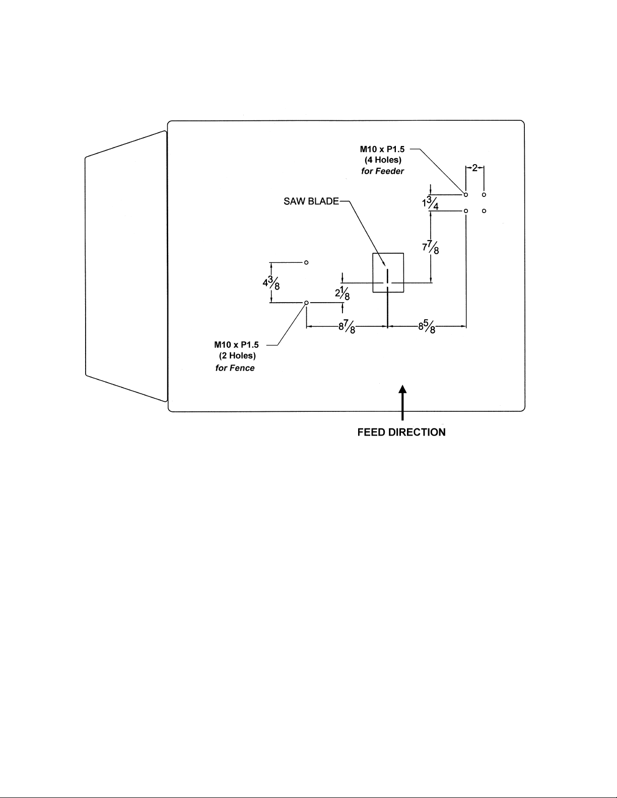
Mounting Hole Location
NOTE: Dimensions are i n inc hes, hole sizes are metric.
Figure 1
8
Page 9

Assembly and Installation
Tools needed for assembly:
8.5mm drill bit
M10 x 1.5P tap
17mm wrench
Remove the cl ear pl astic from around t he Stock
Feeder and Fence Assembly.
Exposed metal surfaces have been given a
protectiv e coating at the fact ory. This should be
removed wit h a soft cloth moistened with a good
commercial solvent, such as kerosene or
mineral spirits. Do not use acet one, gasoline, or
lacquer thinner for this purpose. Do not get
solvents near pl asti c or rubb er par ts, and d o not
use an abrasive pad because it may scratch
metal surfaces.
The Stock F eeder should b e m ount ed to a b and
saw table in a well -lit area. Leav e enough space
around the work area f or loadi ng and off -loadi ng
stock and general maintenance.
The Stock Feeder and the
band saw to which you are mounting it
should both be disconnected from power
during installation.
Follow these steps to assemble and install the
Stock Feeder and Fenc e:
Use the diagram in F igure 1 (page 8) to i dentif y
the proper loc ati on for marking the hol e patt erns
on the band sa w table. Do not drill and tap t he
holes yet, only mark them.
Mounting the Fence
1. The fence must be parallel with the blade
for accurate cuts as well as for safety. To
achieve this, mark the location of the near
hole for the Fence based on the di m ensions
in Figure 1, page 8. Drill and tap the near
hole then place the fence over the hole
pattern. I nsert an M10 x 30 hex cap screw
with lock washer into the near hole, as
shown in Figure 2. With a 17mm wrench,
make the screw snug. Do not tighten
completely.
2. Loosen t he handle (A, Fi gure 3) and rotate
the knob (B, F i gure 3) unti l the f ence i s right
up to the blade; that is, the scale on the
fence should be at “0” .
Figure 2
Figure 3
9
Page 10

3. Tighten the handle (A, Figure 3). If
necessary, m ove the Fence sli ghtly to bring
it parallel with the blade.
4. When satisfied, mark the location of the
second hole using the hole in the Fence
base as your template.
5. Remove the Fence from the tabl e, and drill
and tap the second hole.
6. Place the Fence over the hole pattern again,
and secure the F ence to the tabl e with two
M10 x 30 hex cap scre ws and t wo M1 0 loc k
washers. Tighten firmly.
Mounting the Feeder
1. Screw the handle (Fi gure 4) all t he way into
the threaded hole of t he St oc k Feeder .
NOTE: If the mounting surface is narrow, a
bracket (not provided) must be attached to
support the Stock Feeder. Figure 5 shows an
example.
Figure 4
The Stock Feeder is heavy.
Use a hoist during installation procedures.
Failure to compl y may cause inju ry!
2. Figur e 6 shows the proper met hod of lifting
the Stock Feeder with a hoist. Place one
end of the strap or rope around the motor
mount and the ot her end ar ound the handl e,
as shown.
3. Lift the Stock Feeder carefully into place
over the hole pat tern previously marked on
the band saw table, and verify that the hole
pattern lines up correctly with the holes in
the Stock Feeder base.
4. Remove the Stock Feeder, and drill and tap
the four holes.
5. Secure the Stock Feeder to the table with
four M10 x 30 hex cap screws and f our M 10
lock washers. See Figur e 7.
6. It is important that the serrated roll ers of the
Stock Feeder are properly positioned in
reference to t he blade. Figure 8 shows how
the center of the rollers should be aligned
with the front tips of the blade teeth. The
gearbox top cov er is ali gned wit h the roll er s,
so you can use the top cover’s center for
making this ali gnm ent. S ee Figure 8.
Figure 5
Figure 6
Figure 7
10
Page 11

Grounding Instructions
Electrical connections must
be made by a qualified electrician in
compliance with all relevant codes. This
machine must be properly grounded to help
prevent electrical shock and possible fatal
injury.
As received from the factory, the PF-BS Stock
Feeder will run on either 230 volt or 460 volt,
depending upon your particular model. Make
sure the voltage of your power supply matc hes
the specifications on the motor plate of the
machine.
You may ei ther connect an appropriat e UL/CSA
listed pl ug or “hard-wire” the mac hine di rectly t o
a control panel. If hard-wired to a panel, make
sure a disconnect is available for the operator.
The Stock Feeder must comply with all local and
national codes after being wired. If it is to be
hard-wired, make sure the fuses have been
removed or the breakers have been tripped in
the circuit to which the Stock Feeder will be
connected. Pl ace a warning placard on t he fuse
holder or circuit breaker to prevent it being
turned on while t he machine is being wired.
Refer to “El ectrical Connect ions” on page 23 f or
connecting the motor leads.
This mac hine m ust be grounded. I n the event of
a malfuncti on or break down, groundi ng prov i des
a path of l east resistance f or elect ric current, to
reduce the ri sk of elect ric shock to the oper ator.
Improper connection of the equipmentgrounding conductor can result in a risk of
electric shock. The conductor, with insulation
having an outer surface that is green with or
without yellow stripes, is the equipmentgrounding conductor. If repair or replacement of
the electric cord or plug is necessary, do not
connect the equi pment-grounding c onduc tor to a
live terminal.
Repair or replace a damaged or worn cord
immediately.
Figure 8
Recommended Gauges (AWG) of Extension Cords
Extension Cord Length *
25
50
75
100
150
Amps
< 5 16 16 16 14 12 12
feet
feet
feet
feet
feet
200
feet
Extens ion Cords
If an ext ension c ord i s necessary m ak e sure t he
cord rating i s suitable for the am perage listed on
the machine's motor plate. An undersize cord
will cause a drop in line voltage resulting in loss
5 to 8 16 16 14 12 10 NR
8 to 12 14 14 12 10 NR NR
12 to 15 12 12 10 10 NR NR
15 to 20 10 10 10 NR NR NR
of power and overheating.
The chart in Figure 9 shows the correct size
21 to 30 10 NR NR NR NR NR
cord to use based on cord length and motor
plate amp rating. If in doubt, use the next
heavier gauge. The smaller the gauge number
the heavier the cor d.
*based on li miting th e lin e vol tage drop to 5V at 150 % of t h e
rated amp eres.
NR: Not Recommended.
Figure 9
11
Page 12

Adjustments
Fence Movement
To move t he fence toward or away from the saw
blade, loosen the l oc k handle (A, Figure 10) and
rotate the knob (B, Fi gur e 10) .
A millimeter scale is inscribed on the edge of the
rack (C, Figure 10).
After adjustment, re-tighten lock handle (A,
Figure 10).
Spring Tension
The amount of tension directed against the
workpiece is controlled by the spring, and is
adjustable. Regulate the tension on the spring
by turning t he hex nut , shown in Fi gure 11. Turn
the hex nut clockwise to increase tension,
counterclockwise to decrease tension.
Arm Positioning
The arm of the Stock Feeder can be pulled
away from the blade and secured there by
pushing up the stop rod (Figure 11) into the hole
in the bracket . NO T E: Make sure the stop rod i s
pushed up as far as it will go i nto t he hole.
To release the arm, pull back slightly on the
handle of the Stock Feeder, and pull the stop
rod downward out of the hole. Carefully allow
the arm to swing back toward the bl ade.
The arm will swing back
toward the b lade with force w hen the spring
is tensioned. Guide the arm back without
letting it hit the saw blad e.
Figure 10
Figure 11
Rollers to Blade Distance
The distance of the serrat ed rollers to the band
saw blade can be fine-adjusted with the hex
nuts (Figure 12) .
1. Loosen outer hex nut ( B, Figure 12).
2. Pull back on the Stock Feeder arm, and
turn the inner hex nut (A, Figure 12) as
needed.
3. Lock the setti ng by tightening the outer hex
nut (B, Figure 12) up agai nst the inner hex
nut (A, Figure 12).
Figure 12
12
Page 13

Changing Feed Rate
1. Loosen the two hex nuts (one is shown in
Figure 13) t hat hold the mot or to the motor
mount. Use a 12mm wrench. Do not remove
the hex nuts, loosen them only enough so
that the motor can be pivoted.
2. Pivot the motor c ounterclockwise, as shown
in Figure 13. This will produce slack in the
belt.
3. Open the pulley cover door (Figure 14) by
unscrewing the knob.
4. Roll the belt into the appropriate pulley
groove for the desi red feed rate. A label is
affixed t o the inside of the door (Figure 14)
that shows the configurations for belt
position/feed rate in both feet per minute
and meters per mi nute. This feed rate char t
is also reproduced on page 16.
5. W hen the belt has been changed, close the
pulley door and tighten the knob.
6. Rotate the motor clockwise to tension the
belt. Proper tension is achieved when the
belt can be deflected approximately 3 to
5mm with slight finger pressure.
Figure 13
7. Tighten the two hex nut s (Fi gur e 13) .
Operating Controls
The control switch (Figure 15) turns on the
Stock Feeder motor, and also helps determine
feed rate in c onjunction with t he pulley position.
“Fast” and “Sl ow” are identifi ed by the universal
symbols of hare and tortoise.
Operation
IMPORTANT: Before attempting operation of
this stock feeder in conjunction with a band sa w,
you should be thoroughly familiar with the
operating and safety instructions that were
included with the band saw.
Keep hands away from
rollers, spring, and other pinch points of the
Stock Feeder during operation. Failure to
comply may cause injury.
The following are basic steps for operating the
Stock Feeder.
1. Make sure the band saw is working pr operl y
and that the blade is sharp; and that all
guards are properly installed.
Figure 14
Figure 15
13
Page 14

2. Set the desired rate of feed on the Stock
Feeder by moving the belt to the proper
pulley grooves. Proper rate of feed will
depend upon the hardne ss and thick ness of
the workpiece, and is best learned through
experience.
3. Set the Fence so that t he dimension on the
scale (C, Figure 10) matches the desired
thickness of the workpiece. Secure the
Fence in position with the locking handle.
4. Turn on the band saw and the Stock
Feeder, and carefully feed the workpiece
through the blade.
NOTE: If a jam should occur whil e feeding, turn
off the band saw and the Stock Feeder, pivot the
Stock Feeder out of the way, and remove the
workpiece. Retur n the Stock Feeder to position
and begin the cut over again.
Maintenance
Before performing any
maintenance on the Stock Feeder,
disconnect it from the electrical supply by
pulling out the plug or switching off the
breaker. Also make sure the band saw is
disconnected from power. Failure to comply
may cause serious injury.
If the power cord is worn, cut, or damaged in
any way, have it repl ac ed immediately.
Frequently blow out dust and chips from the
Stock Feeder with c om pr essed air.
Lubrication
Gearbox
The Stock Feeder i s shipped with oi l install ed in
the gearbox. Check the oil about every 3 months
and top off as necessary with a good quality
general-purpose gear oi l.
To add oil to the gearbox:
1. Loosen and remove the oil cap (Figure 16).
2. Fill with oil up t o level, by observing t he level
indicator (Figure 17).
3. Re-install the oil cap.
Figure 16
Figure 17
14
Page 15

A
Arm Axis
Keep the axis of t he arm lubricated with a good
quality general purpose grease, inserted thr ough
the grease fitting (Figure 18).
Figure 18
Fence
t least once a week, plac e a li ght coat of oil on
the sliding column of the fence. Also place a
drop of oil on each roll er pin. See Figure 19.
Figure 19
Troubleshooting
Trouble Probable Cause Remedy
Not connected to power source. Check power connections.
Feeder will not start .
Feed rate is not
sufficient ; or machine
has low power.
Fuse blown, or cir c uit break er tr ipped. Replace fuse, or reset circuit breaker .
Cord damaged. Replace cord.
Belt not situated in correct pulley
grooves to achieve desired speed.
Extension cord too light or too long.
Low current fr om el ectri c al suppl y . Contact a qualified electrician.
Install belt in c or r ect pulley grooves.
[page 13]
Replace with adequat e si z e and
length cord. [page 11]
15
Page 16

Feed Rate/Belt Position
16
Page 17

Replacement Parts
Replacement part s are li sted on the f ollowing page s. To order par ts or reac h our servi ce depar tment, call
1-800-274-6848 between 7:00 a.m. and 6:00 p.m. (CST), Monday through Friday. Having the Model
Number and Serial Number of your machine available when you call will allow us to serve y ou quickly and
accurately.
17
Page 18

Parts List: Fence Assembly
Index No. Part No. Description Size Qty
1...............PFBS-101............... Roller Fence...................................................... ...................................1
2...............PFBS-102............... Column .............................................................. ...................................1
3 ...............PFBS-103 ............... Rack ................................................................. ...................................1
4...............TS-1502031............Socket Head Cap Screw.................................... M5x12........................3
5...............TS-2361081............Lock Was h e r......................................................M8..............................4
6...............TS-1490051............Hex Cap Screw..................................................M8x30........................4
7...............PFBS-107............... Roller Mounting Strip ......................................... ...................................2
8...............TS-1502081............Socket Head Cap Screw.................................... M5x35 ........................8
9...............PFBS-109............... Fence Roller...................................................... .................................15
10.............PFBS-110............... Mounting Base................................................... ...................................1
11.............TS-2361101............Lock Wash e r ......................................................M10............................2
12.............TS-1491041............Hex Cap Screw..................................................M10x30......................2
13.............PFBS-113............... Lock Handle ...................................................... ...................................1
14.............TS-0680061............Flat Washer....................................................... 1/2".............................1
15 .............PFBS-115...............Stud .................................................................. ...................................1
16.............PFBS-116............... Pinion................................................................ ...................................1
17.............PFBS-117............... Knob.................................................................. ...................................1
18.............PFBS-118............... Pin..................................................................... 6x36...........................1
19.............TS-1524061............Socket Set Screw .............................................. M8x25 ........................1
20.............TS-2361081............Lock Wash e r ......................................................M8..............................1
21.............TS-1540061............Hex Nut............................................................. M8 ..............................1
18
Page 19

Fence Assembly
19
Page 20

Parts List: Feeder Assembly
Index No. Part No. Description Size Qty
1...............BB-6202ZZ..............Ball Beari ng.......................................................6202ZZ.......................1
2...............BB-6204Z................ Ball Bearing....................................................... 6204Z.........................1
3...............BB-6205Z................ Ball Bearing....................................................... 6205Z.........................1
4...............BB-6206Z................ Ball Bearing....................................................... 6206Z.........................1
5...............PFBS-205............... Gearbox Top Cover........................................... ...................................1
6...............TS-1503051............Socket Head Cap Screw.................................... M6x20........................4
7...............TS-1551041............Lock Was h e r......................................................M6..............................4
8...............PFBS-208............... Oil Cap.............................................................. ...................................1
9...............PFBS-209............... "O" Ring............................................................. ...................................1
10.............PFBS-210............... Wor m Gea r........................................................ ...................................1
11.............PFBS-211............... Gear Shaft......................................................... ...................................1
12.............PFBS-212............... Key.................................................................... 8x7x20........................ 1
13.............PFBS-213............... Key.................................................................... 8x7x90........................ 1
14.............TS-1550111............Flat Washer....................................................... M20............................1
15.............TS-2310201............Hex Nut............................................................. M20............................1
16.............PFBS-216............... Reduction Gearbox............................................ ...................................1
17.............PFBS-217............... Level Indicator................................................... ...................................1
18.............PFBS-218............... Grease Fitting.................................................... ...................................1
19.............PFBS-219............... Handle............................................................... ...................................1
20.............PFBS-220............... Wor m Gea r Co ver .............................................. ...................................1
21.............TS-1551041............Lock Wash e r ......................................................M6..............................3
22.............TS-1503041............Socket Head Cap Screw.................................... M6x16........................3
23.............PFBS-223............... Gearbox Bottom Cov er ...................................... ...................................1
24.............PFBS-224............... Retaining Ring................................................... ...................................1
25.............TS-1551041............Lock Wash e r ......................................................M6..............................4
26.............TS-1503051............Socket Head Cap Screw.................................... M6x20........................4
27.............PFBS-227............... Roller Cover ...................................................... ...................................1
28.............PFBS-228............... Mounting Base................................................... ...................................1
29.............TS-1491041............Hex Cap Screw..................................................M10x30......................4
30.............TS-2361101............Lock Wash e r ......................................................M10............................4
31.............PFBS-231............... Stop Rod........................................................... ...................................1
32.............PFBS-232............... "E" Clip.............................................................. ...................................1
33.............PFBS-233............... Stop Plate.......................................................... ...................................1
34.............TS-1491031............Hex Cap Screw ................................................. M10x25 ......................4
35.............TS-2361101............Lock Wash e r ......................................................M10............................4
36.............PFBS-236............... Worm................................................................. ................................... 1
37.............PFBS-237............... Key.................................................................... 5x5x25........................ 1
38.............PFBS-238............... Wor m Gea r Cap................................................. ...................................1
39.............PFBS-239............... Compensating Collar ........................................ ...................................1
40.............PFBS-240............... Oil Seal.............................................................. ................... ................1
41.............TS-1551041............Lock Wash e r ......................................................M6..............................4
42.............TS-1503071............Socket Head Cap Screw.................................... M6x30........................4
43.............PFBS-243............... Pulley Housi ng................................................... ...................................1
44.............PFBS-244............... Wor m Gea r Pu l ley............................................. ...................................1
45.............TS-1550041............Flat Washer....................................................... M6..............................1
46.............TS-1482031............Hex Cap Screw..................................................M6x16........................1
47.............PFBS-247............... Motor Pulley...................................................... ...................................1
48.............TS-1550041............Flat Washer....................................................... M6..............................1
49.............TS-1503041............Socket Head Cap Screw.................................... M6x16........................1
50.............PFBS-250............... Belt.................................................................... M-18 ...........................1
51.............PFBS-251............... Pulley Housi ng Cover........................................ ...................................1
52.............TS-1551041............Lock Wash e r ......................................................M6..............................2
53.............TS-1503041............Socket Head Cap Screw.................................... M6x16........................3
54.............PFBS-254............... Motor................................................................. 1/2 HP, 230V, 3Ph......1
................. PFBS-254A............. Motor................................................................. 1/2 HP, 460V, 3Ph......1
................. PFBS-254B............. Motor................................................................. 1/2HP, 230V, 1Ph.......1
................. PFBS-254CA ..........Capacitor (only for 1 phase) – Not shown........... 350V 25uf...................1
20
Page 21

Index No. Part No. Description Size Qty
55.............TS-1550061............Flat Washer....................................................... M8..............................2
56.............TS-1490061............Hex Cap Screw..................................................M8x35........................1
57.............PFBS-257............... Lock Screw........................................................ ...................................1
58.............TS-2361081............Lock Wash e r ......................................................M8..............................2
59.............TS-1540061............Hex Nut............................................................. M8 ..............................2
60.............PFBS-260............... Key.................................................................... 5x5x30........................ 1
61.............PFBS-261............... Pulley Housi ng Door.......................................... ...................................1
62.............PFBS-262............... Hinge................................................................. ...................................1
63.............TS-2171012............Machine Screw, Pan Head.................................M4x6.......................... 4
64.............TS-1540021............Hex Nut............................................................. M4 ..............................4
65.............PFBS-265............... Knob.................................................................. ...................................1
66.............PFBS-266............... Spring Hinge...................................................... ...................................1
67.............TS-2361081............Lock Wash e r ......................................................M8..............................1
68.............TS-1490031............Hex Head Bolt ................................................... M8x20 ........................1
69.............TS-2361081............Lock Wash e r ......................................................M8..............................3
70.............TS-1490041............Hex Cap Screw ................................................. M8x25 ........................3
71.............TS-1490051............Hex Cap Screw ................................................. M8x30 ........................1
72.............PFBS-272............... Spring Adjusting Rod......................................... ...................................1
73.............TS-155009..............Flat Washe r....................................................... M14............................1
74.............PFBS-274............... Bumper Ring...................................................... ...................................1
75.............TS-154009..............Hex Nut.............................................................M14............................3
76.............PFBS-276............... Spring Guide Set (2 Pieces/Set)......................... ...................................1
77.............PFBS-277............... Spring................................................................ ...................................1
78.............PFBS-278............... Switch Box Kit.................................................... ...................................1
79.............PFBS-279............... Switch Kit........................................................... ...................................1
80.............PFBS-280............... Spacer............................................................... ...................................1
81.............PFBS-281............... Bushing............................................................. ...................................1
82.............PFBS-282............... Steel Roller........................................................ ..................................2
83.............PFBS-283............... Oil Seal..............................................................35...............................1
84.............PFBS-284............... Oil Seal..............................................................115.............................2
85.............PFBS-285............... Oil Seal..............................................................20x35x7......................1
86.............PFBS-286............... Label, Feed Rate (not shown)............................ ................................... 1
87.............PFBS-287............... Warning Label (not shown)................................ ...................................1
21
Page 22

Feeder Assembly
22
Page 23

Electrical Connections
23
Page 24

WMH Tool Gr ou p
2420 Vantage Drive
Elgin, Illinois 60123
Phone: 800-274-6848
www.wmhtoolgroup.com
24
 Loading...