

Page 1

This .pdf document is bookmarked
Operating Instructions and Parts Manual
4-Speed Stock Feeders
Models PF-31, PF-33, PF-41, PF-43
Powermatic
427 New Sanford Road
LaVergne, Tennessee 37086 Part No. M-1790800
Ph.: 800-274-6848 Revision C1 02/2014
www.powermatic.com Copyright © 2014 Powerm atic
Page 2

Warranty and Service
Powermatic warrants every product it sells against manufacturers’ defects. If one of our tools needs service or repair,
please contact Technical Service by calling 1-800-274-6846, 8AM to 5PM CST, Monday through Friday.
Warranty Period
The general warranty lasts for the time period specified in the literature included with your product or on the official
Powermatic branded website.
• Powermatic products carry a limited warranty which varies in duration based upon the product. (See chart
below)
• Accessories carry a limited warranty of one year from the date of receipt.
• Consumable items are defined as expendable parts or accessories expected to become inoperable within a
reasonable amount of use and are covered by a 90 day limited warranty against manufacturer’s defects.
Who is Covered
This warranty covers only the initial purchaser of the product from the date of delivery.
What is Co vered
This warranty covers any defects in workmanship or materials subject to the limitations stated below. This warranty
does not cover failures due directly or indirectly to misuse, abuse, negligence or accidents, normal wear-and-tear,
improper repair, alterations or lack of maintenance.
Warranty Limitations
Woodworking products with a Five Year Warranty that are used for commercial or industrial purposes default to a
Two Year Warranty. Please contact Technical Service at 1-800-274-6846 for further clarification.
How to Get Technical Support
Please contact Technical Service by calling 1-800-274-6846. Please note that you will be asked to provide pro of
of initia l p u rch a s e whe n calling. If a product requires further inspection, the Technical Service representative will
explain and assist with any additional action needed. Powermatic has Authorized Service Centers located throughout
the United States. For the name of an Authorized Service Center in your area call 1-800-274-6846 or use the Service
Center Locator on the Powermatic website.
More Informa t io n
Powermatic is constantly adding new products. For complete, up-to-date product information, check with your local
distributor or visit the Powermatic website.
How S tate Law Applies
This warranty gives you specific legal rights, subject to applicable state law.
Limitations on This Warranty
POWERMATIC LIMITS ALL IMPLIED WARRANTIES TO THE PERIOD OF THE LIMITED WARRANTY FOR EACH
PRODUCT. EXCEPT AS STATED HEREIN, ANY IMPLIED WARRANTIES OF MERCHANTABILITY AND FITNESS
FOR A PARTICULAR PURPOSE ARE EXCLUDED. SOME STATES DO NOT ALLOW LIMITATIONS ON HOW
LONG AN IMPLIED WARRANTY LASTS, SO THE ABOVE LIMITATION MAY NOT APPLY TO YOU.
POWERMATIC SHALL IN NO EVENT BE LIABLE FOR DEATH, INJURIES TO PERSONS OR PROPERTY, OR
FOR INCIDENTAL, CONTINGENT, SPECIAL, OR CONSEQUENTIAL DAMAGES ARISING FROM THE USE OF
OUR PRODUCTS. SOME STATES DO NOT ALLOW THE EXCLUSION OR LIMITATION OF INCIDENTAL OR
CONSEQUENTIAL DAMAGES, SO THE ABOVE LIMITATION OR EXCLUSION MAY NOT APPLY TO YOU.
Powermatic sells through distributors only. The specifications listed in Powermatic printed materials and on the official
Powermatic website are given as general information and are not binding. Powermatic reserves the right to effect at
any time, without prior notice, those alterations to parts, fittings, and accessory equipment which they may deem
necessary for any reason whatsoever.
Product Listing with Warranty Period
90 Days – Parts; Consumable items
1 Year – Motors, Machine Accessories
2 Year – Woodworking Machinery used for industrial or commercial purposes
5 Year – Woodworking Machinery
NOTE: Powermatic is a division of JPW Industries, Inc. References in this document to Powermatic also apply to
JPW Industries, Inc., or any of its successors in interest to the Powermatic brand.
2
Page 3

Table of Contents
Warranty and Servic e .............................................................................................................................. 2
Table of Contents .................................................................................................................................... 3
Warning ................................................................................................................................................... 4
Introduction ............................................................................................................................................. 6
Desc ription ................................................................................................................... ........................... 6
Specifica tions ................................................................................................................ .......................... 6
Features and Terminology ....................................................................................................................... 7
Unpac king ............................................................................................................................................... 8
Contents of the Shipping Container ...................................................................................................... 8
Assembly ................................................................................................................................................ 9
Grounding Inst r uc tions ........................................................................................................................... 11
Extension Cords................................................................................................................................. 12
Adjustments .......................................................................................................................................... 12
Basic Feeder Mov em ents ................................................................................................................... 12
Edgewise Stock Feeder P osi tion ........................................................................................................ 12
Speed Selecti on ................................................................................................................................. 12
Operating Controls ................................................................................................................................ 13
Operation .............................................................................................................................................. 1 3
General Operating Instructions ........................................................................................................... 14
When Used with a Shaper .................................................................................................................. 14
When Used with a Table Saw............................................................................................................. 15
When Used with a Jointer .................................................................................................................. 15
Roller Removal/Replacement ............................................................................................................. 16
Lubrication ......................................................................................................................................... 17
Replacement Parts ................................................................................................................................ 18
PF-31/33 Feeder Body ....................................................................................................................... 19
Parts List: PF- 31/33 Feeder Body....................................................................................................... 20
PF-41/43 Feeder Body ....................................................................................................................... 22
Parts List: PF- 41/43 Feeder Body....................................................................................................... 23
Parts List: Motor A ssembly for PF-31/33 and PF-41/43 ...................................................................... 25
Feeder Mounting Assembly for PF-31/33 and PF-41/43...................................................................... 26
Electri c al Connec tions – 3 Phase only ................................................................................................... 28
3
Page 4

Warning
1. Read and understand the ent ire owner’s manual before att em pting assembly or operation.
2. Read and understand the warnings po sted on the m achine and i n thi s manual. Fail ure to comply wit h
all of these warnings m ay cause seriou s i njury.
3. Replace the warning labels if they become obscured or removed.
4. This stock feeder is designed and intended for use by properl y trained and experienced personnel
only. If you are not familiar with the proper and safe operation of a stock feeder, do not use until
proper trai ning and k nowledge have been obtained.
5. Do not use thi s stock f eeder for other than its i ntended use. If used for other purposes, Powerm atic
disclaim s any real or i mplied warrant y and h olds itsel f harml ess from any injury t hat may r esult f rom
that use.
6. Always wear approved safety glasses/face shields while using this stock feeder. Everyday
eyeglasses only have impact resistant lenses; they ar e not safety glasses.
7. Bef ore operating thi s stock feeder, remove tie, rings, watches and other jewelry, and roll sl eeves up
past the elbows. Rem ove all loose cl othing and confi ne long hair. Non-sl ip foot wear or anti-ski d floor
strips are recommended. Do not wear gloves.
8. Wear ear protector s (plugs or muffs) during extended periods of oper ation.
9. Some dust created by power sanding, sawing, grinding, drilling and other construction activities
contain chemi cals known to cause cancer , bir th defects or other r eproductiv e harm . Some exampl es
of these chemic als are:
• Lead from lead based paint.
• Crystalli ne sil ic a from bricks, cement and other masonry pr oduc ts.
• Arsenic and chromium from chemically treated lumber.
Your risk of exposure varies, depending on how often you do this type of work. To reduce your
exposure to these chemicals, work in a well-ventilated area and work with approved safety
equipment, such as face or dust masks that are specifically designed to filter out microscopic
particles.
10. Do not operate this machine while ti r ed or under t he influence of drugs, alcohol or any medic ation.
11. Mak e c er tain the switch is in the OFF position before connecting the machine to the power supply.
12. Mak e c er tain the machine is properly grounded.
13. Mak e all machine adjustments or mai ntenance with the machine unplugged from the power source.
14. Remove adjusting keys and wrenches. Form a habit of checking to see that keys and adjusting
wrenches are removed from the machine before turning i t on.
15. Keep safety guards in place at all times when the machine is in use. If removed for maintenance
purposes, use extreme caution and replace the guards immediately upon completion of maintenance.
16. Mak e sure t he stoc k feeder is firmly secured to an auxiliary m achi ne before use.
17. Check damaged parts. Before further use of the machine, a guard or other part that is damaged
should be carefully checked to determine that it will operate properly and perform its intended
function. Chec k for alignment of moving par ts, binding of moving parts, breakage of parts, mounting
and any other condi ti ons that m ay affect its operati on. A guard or ot her part that i s damaged should
be properly repaired or replaced.
18. Pr ov ide for adequate space surrounding work area and non-glare, ov er head lighting.
19. Keep the floor around the machine cl ean and free of scrap material, oil and grease.
20. Keep v isitors a safe distance from the work area. Keep children away.
4
Page 5

21. Mak e y our workshop chi ld proof with padlocks, m ast er switc hes or by r em oving starter keys.
22. Giv e your work undivi ded attention. Looki ng around, carryi ng on a conversati on and “horse-play” ar e
careless acts that can r esul t in serious injury.
23. M aintain a balanc ed stance at all t imes so that you d o not fall or lean against mov ing parts. Do not
overreach or use exc essive force to perform any machine operation.
24. Use the right tool at the correc t speed and f eed rat e. Do not force a t ool or att achment to do a job for
which it was not designed. T he ri ght tool will do the job better and saf er.
25. Use recommended accessories; improper accessories may be hazardous.
26. Maintain tools with care. Keep tools sharp and clean f or the best and saf est performance. Follow
instructions for lubricating and changing accessories.
27. Disconnect from power both the stoc k f eeder and t he auxi li ary m achine befor e cleani ng. Use a brush
or compressed air to remove chips or debris — do not use your hands.
28. Do not st and on the machine. Serious injury c ould oc c ur if the machine tips over.
29. Never leav e the feeder or auxi liar y machi ne running unatt ended. T urn t he power off and do not l eave
the machine until it comes to a complete stop.
30. Remove loose items and unnecessary work piec es from the area before starti ng the m ac hine.
Familiariz e you rself with the following safety notices used in this manual:
This means that if precautions are not heeded, it may result in mi nor i njur y and/or
possible machine damage.
This means that if precautions are not heeded, it may result in serious injury or possibly
even death.
- - SAVE THESE INSTRUCTIONS - -
5
Page 6

Introduction
This manual is provi ded by Powermatic covering the saf e operation and maint enance procedures f or the
Model PF- 31 (single phase), PF- 33 (three phase), P F-41 (single phase) an d PF-43 (three pha se) Stock
Feeders. This manual contains instructions on installation, safety precautions, general operating
procedures, maintenance instructions and parts breakdown. This machine has been designed and
constructed to pr ovide years of troubl e free operation if used in accordance with i nstructions set f orth in
this manual. If there are any questions or comments, please contact either your local supplier or
Powermati c. P owermatic can also be reached at our web site: www.powermatic.com.
Description
The PF-seri es Stock Feeders hav e a continuous-duty motor and lubri cated gearbox that transmit power
to the roller chain and sprockets to feed rollers, providing superior positive feeding for all types of
materials. The support column is fully adjustable with universal joints, and heavy locking mechanisms
secure the feeder in hori z ontal, vertical or angled positions.
Specifications
Model Number ....................................................................... PF-31, PF-33 ......................... PF-41, PF-43
Stock Number (1Ph, 115V ) ......................................................... 1790807K .............................. 1790812K
Stock Number (3PH, 230V ) ........................................................ 1790800K .............................. 1790811K
Stock Number (3Ph, 460V ) ......................................................... 1790810K .......................................... na
Height with handle (in.) ..................................................................... 29-1/2 .................................... 2 9-1 /2
Width (in.) ............................................................................................... 18 .................................... 23-1/2
Length – with handle and arm f ully extended (in.) ............................. 43-1/4 .................................... 4 3-1 /4
Column Diameter (i n.) ......................................................................... 2-1/4 ...................................... 2-1 /4
Feed Rollers (Di a. x W) (i n.)........................................ 4-3/4 x 2-3/8 (Qty. 3) .............. 4-3/4 x 2-3/8 (Qty. 4)
Rotation ............................................................................ Forward/Reverse ................... Forward/Reverse
Number of Speeds .................................................................................... 4 ........................................ .... 4
Range of Speeds (FPM) ........................................... 13, 26, 33, 66 (PF-33) ........... 13, 26, 33, 66 (PF-43)
13, 36, 43, 108 (PF-31) 13, 36, 43, 108 (PF-41)
Distance Between Wheels –Center to Center (in.)...................... 5.07 – 5.90 ........................ 5.23 - 5.93 - 5
Swing (deg.) ......................................................................................... 360 ................................. ....... 36 0
Vertical Movement (in.) ....................................................................... 9-3/4 ...................................... 9-3/4
Horizontal Movement (in.) ...................................................................18.07 ..................................... 18.07
Maximum Height of Rollers Parallel to Tabletop (in.) ........................... 8-1/2 ...................................... 8-1/2
Rollers Vertical Suspension Travel, Appr ox. (i n.) .................................. 9/1 6 ....................................... 9/16
Motor .............................................................................. TEFC, 1HP, 60Hz .................. TEFC, 1HP, 60Hz
Approximate Net Weight (lbs.) .............................................................. 134 ........................................ 150
Approximate Shipping Weight (lbs.) ...................................................... 143 ........................................ 158
The above specifications were current at the time this manual was published, but bec ause of our policy of
continuous im provement, Powerm atic reserves the right t o change specific ations at any time and without
prior notic e, wit hout incurring obligations.
6
Page 7
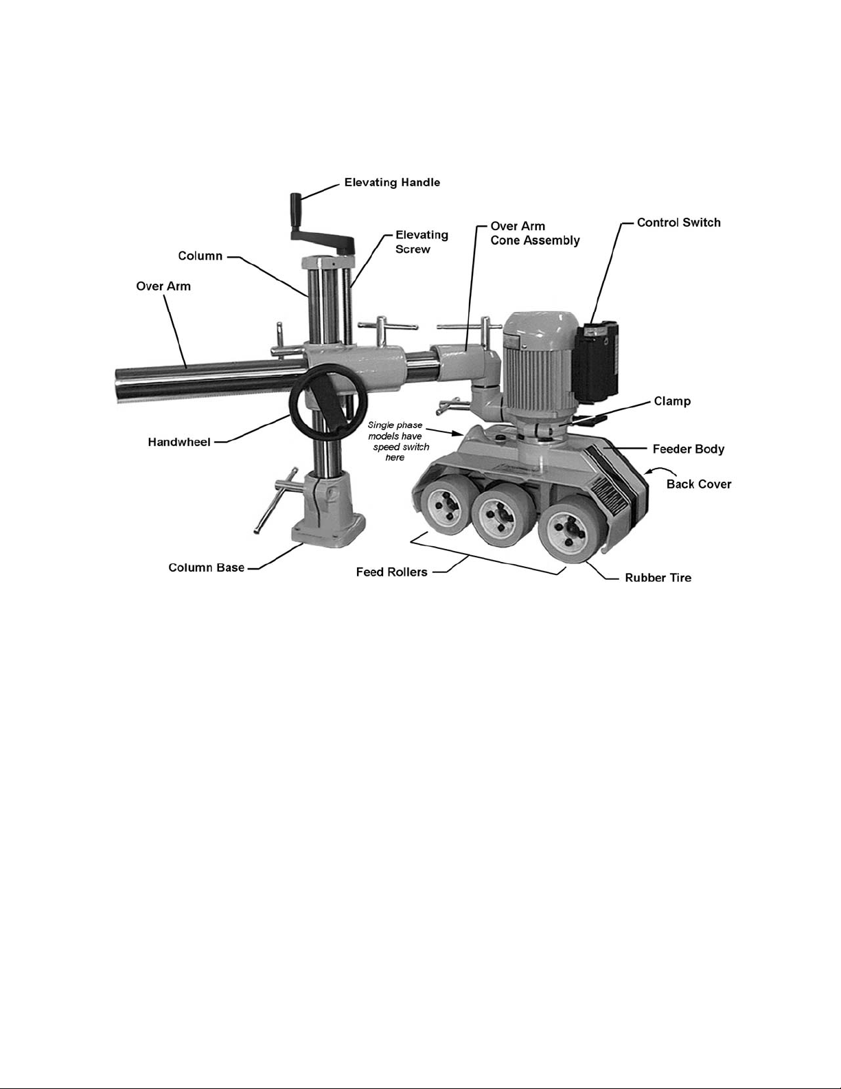
Features and Terminology
Figure 1
7
Page 8

Unpacking
Open both cartons and check for shipping
damage. Report any damage immediately to
your distributor and shipping agent. Do not
discard any shipping material until the Stock
Feeder is assembled and r unning properly.
Compare the contents of the cartons with the
following parts list to make sure all parts are
intact. Mi ssing parts, if any, should be reported
to your distributor. Read the instruction manual
thoroughly for assembly, maintenance and
safety instructions.
Contents of the Shipping Container
Carton #1:
1 Stock Feeder
1 Grease Gun (grease not i ncl uded – follow
instructions on its packaging to fill)
1 Boring Template
1 Owner's Manual (not shown)
1 Warranty Car d (not shown)
Carton #2:
1 Feeder Mounting Assembly
1 Handle
1 Over Arm
1 Over Arm Cone Assembl y
4 Hex Cap Screws, M12x50 (not shown)
4 Spring Washers, M12 (not sho wn)
Figure 2
Read and understand the entire contents of this manual before attempting set-up
or operation! Failure t o co mply may cause serious injury.
8
Page 9
Assembly
Tools needed for assembly (not provided):
Electric drill
center punch and hammer
10.5mm drill bit
M12 x P1.75 tap
12mm, 14mm and 19mm wrenches
5mm hex wrench
Hardware needed for assembly:
4 M12 spring washers
4 M12 x P1.75 hex cap screws (length will
depend upon thicknes s of table)
Exposed metal areas of the stock feeder have
been factory coated with a protectant. This
should be removed with a soft cloth and a
cleaner/degreaser. Do not use gasoline,
acetone, lacquer thinner or other highly
flammable substances for this purpose. Avoid
getting solvents near plasti c or rubber parts, and
do not use an abrasive pad because it may
scratch metal surfaces.
The stock feeder shoul d be mounted securel y t o
an auxiliary machine in a well-lighted area.
Leave enough space around the work area for
loading and off-loading stock and general
maintenance.
The stock feeder and the
auxiliary machine to which you are mounting
it should both be disconnected from power
during instal lation.
Refer to pages 14 thr ough 16 f or help i n pl aci ng
the stock feeder on a shaper, table saw or
jointer.
1. Rest the feeder mounting assembly on the
table of the auxiliary machine to determine
the mounting location. (Figure 3 shows it
being mounted to a table saw). Keep in
mind the lengt h of the over arm, so that after
it is connected to the feeder mounting
assembly it will hav e enough adjustm ent for
positioni ng the stock feeder where needed.
Mark the table if needed to identify the
position.
IMPORTANT: Locate the feeder mounting
assembly so that you will not drill through
ribs or supports beneath the table surface.
2. Remove the feeder mounting assembly from
the table. Find the boring template t hat was
provided with y our stock feeder, and i dentif y
the centerline spacing for the holes in the
column base for your partic ular model.
Figure 3
9
Page 10

3. Cl ean the table surface, then peel away the
backing from the boring template in
increments, as you carefully apply the
boring template onto the table.
4. Center punch and drill four 10.5mm
diameter hol es in t he tabl e surf ace, then tap
the holes with M12 x P1.75 threads.
5. Peel off the bori ng template and discard.
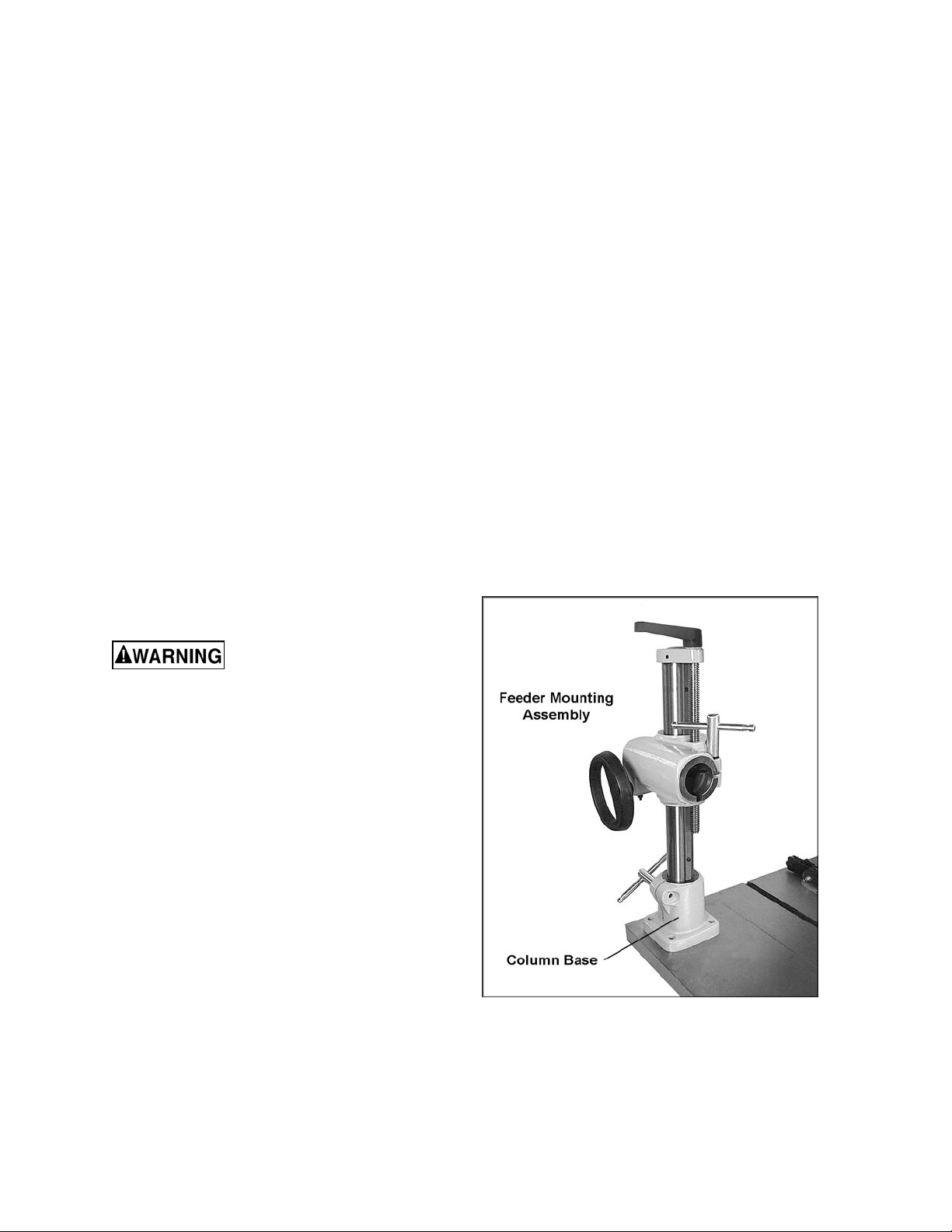
6. Place the column base in position (Figure
4), and align the four holes in the column
base with the hol es in the tabl e. Positi on the
column base so that its locking handle will
be in a convenient posi tion.
7. Insert four M12x50 hex cap screws with f our
M12 spring washers through the holes in the
stand. See Figure 4.
8. Tighten the four screws firmly with a wrench.
9. Install the small handle into the hol e in the
elevating handl e (F igur e 5). Screw the small
handle into the hole, then tighten the hex
nut down against the el ev ating handl e using
a 14mm wrench.
Figure 4
10. The small handle should still be able to
rotate freely. If it does not, loosen the hex
nut, back of f the socket head cap screw with
a 5mm hex wrench as shown, then retighten the hex nut.
11. Remove t he screw from bel ow the bracket ,
then remov e the handwheel (Figure 6).
12. Slide the end of the over arm that has the
rack extendi ng all the way to the edge, into
the bracket ( Figure 7). NOTE: The rack will
slide through the slot inside the bracket.
13. Re-install handwheel, then reinstall screw
(Figure 6). Make sure the rack of the
overarm m eshes properly with the pi nion on
the handwheel shaf t . The ov er arm can now
be moved simply by rotati ng the handwheel.
14. Place the sleeve of the over arm cone
assembly onto the over arm as shown in
Figure 8. Loosen further the two hex cap
screws if needed. Push the cone assem bly
onto the over arm as far as it will go.
15. Tighten the two hex cap screws (Figure 8)
with a 14mm wrench.
Figure 5
Figure 6
The stock feeder is heavy.
The use of an assistant may be necessary.
16. P lace the stock feeder on the tabl e surface,
and lower the ov er arm so that the clam p is
positioned to accept the stock f eeder. (see
“Basic Feeder Movements”, page 12, for
instructions on positioning the over arm.)
Figure 7
10
Page 11

17. Mounting the feeder body may be easier if
you loosen the two hex c ap screws (shown
in Figure 8) and rotate the over arm cone
assembly so that the clamp is toward the
bottom, as shown in Figure 9. Loosen the
handles and rotat e the cones as needed to
get the clamp in position. Re-tighten the
screws and handles before mounting the
feeder body.
18. Unscrew the bolt and the handle ( Figure 9)
from the clam p, and remove the outer half of
the clamp.
19. Posi tion the neck of the stock feeder into the
inner half of the clamp, then attach the out er
half of the clamp. Re-install the bolt and
handle and tighten both of them gradually
and in turns, until the clamp is evenly tight
over the stock feeder neck. NOTE: The
seam between the two halv es of the clamp
will not close entirely.
The handle (Figure 9) is adjustable. To
tighten it , rotate the handle cl ockwise, then
lift out on the handle, rotate it
counterclockwise on the pin and release it,
making sure it re-seats itself on the pin.
Continue this procedure until tight. (This
adjustable feature allows the handle to be
re-positioned at any time while remaining
tight.)
Figure 8
Figure 9
Grounding Instructions
Electrical connections must
be made by a qualified electrician in
compliance with all relevant codes. This
machine must be properly grounded to help
prevent electrical shock and possible fatal
injury.
The PF-seri es Feeders are availabl e in voltages
ranging from 115 to 460, depending on the
model you purchas ed. Make sure the v oltage of
your power supply matches the specifications on
the motor plat e of the stock feeder.
The Stock Feeder is not supplied with an
electrical plug. You may either connect an
appropriate UL/CSA listed plug, or “hard-wire”
the machine dir ectly to a service panel.
If the stock feeder is to be hard-wi r ed to a panel,
make sure a disconnect is available for the
operator. Also make sure the fuses have been
removed or the breakers have been tripped in
the circuit to which the stock feeder will be
connected. Pl ace a warning placard on t he fuse
holder or circuit breaker to prevent it being
turned on whi le t he m achine i s being wired. The
stock feeder must comply with all local and
national codes after being wired.
This mac hine must be grounded. In the ev ent of
a malf unction or breakdo wn, grounding prov ides
a path of l east resistance for el ectric current, to
reduce the ri sk of electric shock to t he operator.
Improper connection of the equi pment-grounding
conductor can result in a risk of el ectric shock.
The conductor, with insulation having an outer
surface that is green with or without yellow
stripes, is the equipment-groundi ng c onduc tor. If
repair or replac ement of the elect ric cord or plug
is necessary, do not connect the equipmentgrounding conductor to a live terminal.
11
Page 12

Extens ion Cord s
If an extensi on c or d is necessary, make sure t he
cord rating i s suitable for the am perage listed on
the machine's motor plate. An undersize cord
will cause a drop in line voltage resulting in loss
of power and overheating.
The chart in Figure 10 shows the correct size
cord to use based on cord length and motor
plate amp rating. If in doubt, use the next
heavier gauge. The smaller the gauge number
the heavier the cor d.
Adjustments
Basic Feeder Movements
Refer to Figure11.
To raise or lower the over arm, loosen handle
(A) and rotate elevating handle (B). When
adjustment is complete, re-tighten handle (A).
Recomm end ed Ga ug es (A WG ) of Extensi on Co rd s
Extension Cord Length *
25
50
75
100
150
200
Amps
< 5 16 16 16 14 12 12
5 to 8 16 16 14 12 10 NR
8 to 12 14 14 12 10 NR NR
12 to 15 12 12 10 10 NR NR
15 to 20 10 10 10 NR NR NR
21 to 30 10 NR NR NR NR NR
*based on li miting the lin e voltage drop to 5V at 150% of th e
rated amp eres.
NR: Not Recommended.
feet
feet
feet
feet
feet
feet
Figure 10
To move the ov er arm forward or back, loosen
handle (C) and rotate handwheel (D). When
adjustment is complete, re-tighten handle (C).
To swing the over arm acr oss the table, loosen
handle (E) and swing the over arm to desired
position. Re-tight en handl e (E) before oper ati ng
the stock feeder.
To rotate t he cones to help position t he feeder,
loosen handles (F). Tighten handles when
adjustment is complete.
To rotate the stock feeder on its vertical axis,
loosen handle (G) just enough that the stock
feeder will freely rotate. Re-tighten handle (G)
before operating the stock feeder.
Edgewise Stock Feeder Position
The stock feeder can be turned “edgewise” so
that the f eed is al ong the side of the workpiece.
This is usef ul when edgi ng stoc k on a shap er or
jointer. The position is achieved using a
combination of cone rotations, as shown in
Figure 12.
Figure 11
Figure 12
Speed Selection
The stock feeder has f our speed s, or feed r ates:
13, 26, 33 and 66 FPM for the 3-Phase models;
and 13, 36, 43 and 108 FPM for the 1-Phase
models. These speeds are achieved by a
combination of gear position and the setting of
the control switch.
12
Page 13
Disconnect stock feeder
from power so urce before opening the back
cover or switching gears.
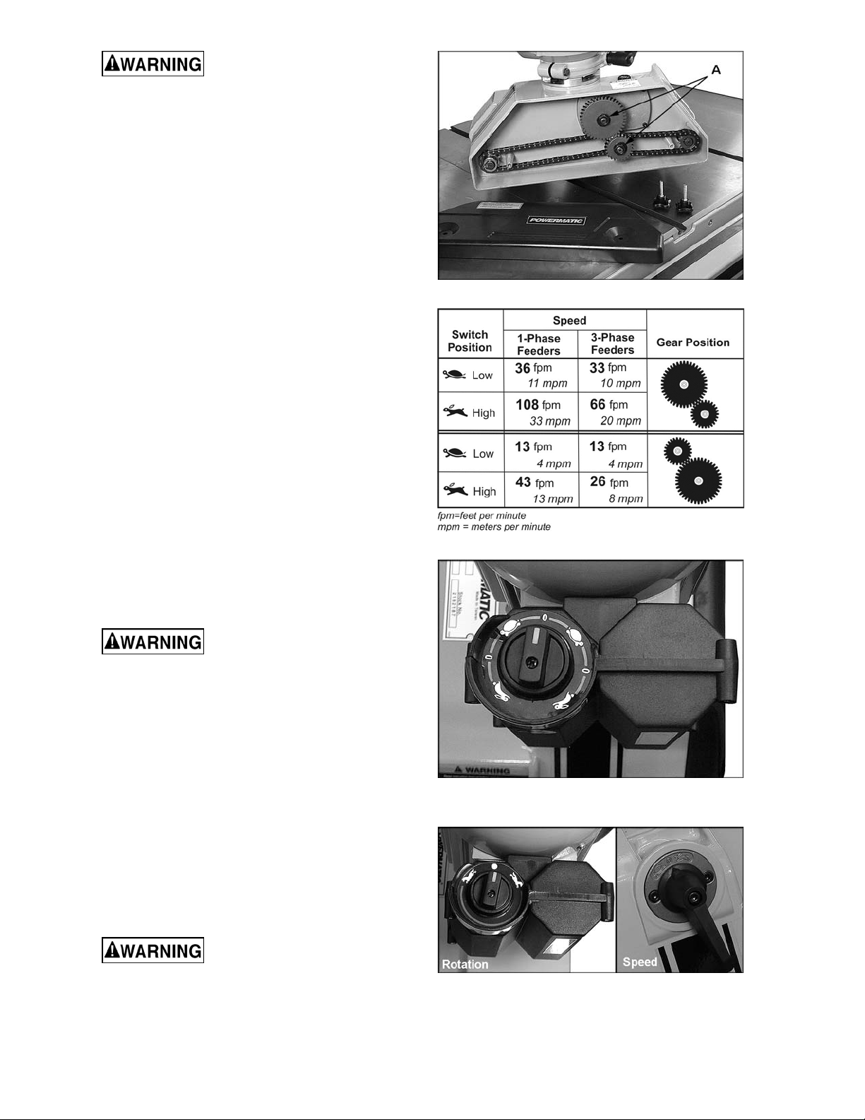
To change the positi on of t he gear s:
1. Disconnect machine from power source.
2. Unscrew the two k nobs and pull off the back
cover to ex pose the gear system, shown in
Figure 13.
3. Remove hex nuts and flat washers (A,
Figure 13) with a 14mm wrench.
4. Figure 14 shows the relationship of gear
position t o c r eate each of the four speeds. A
similar chart is affixed to the inside of the
back cover on the Stoc k Feeder .
5. Install new gear configuration, making sure
the notch in each gear slides into the
keyway of the s haft. Push the gears as f ar
as they will go onto the shaf ts.
6. Install flat washer and hex nut (A, Figure 13)
on each shaft, and tighten.
7. Re-install bac k c ov er and tighten knobs.
Figure 13
Operating Controls
The control switch f or 3-phase units i s shown i n
Figure 15; the cont rol switches f or 1-phase unit s
are shown in Figure 16. Speeds are indi c ated by
the universal symbols of hare (high speed) and
tortoise (low speed). The switch can be turned
for either f or ward or rev er se di rection.
If a jam should occur while
feeding a w orkpiece, DO NOT turn the sto ck
feeder to reverse w hi le th e auxi liary mach in e
is still running in forward direction.
If a workpiece becomes jammed, turn off the
stock feeder, and then turn off the auxiliary
machine. Raise the stoc k feeder in order to clear
the workpiece. Then re-set the feeder height,
turn on auxiliar y machine and stock feeder, and
begin the feed over again.
Operation
IMPORTANT: Before operating the stock
feeder, you should be thoroughly familiar with
the safety and operating instructions that
accompanied the auxiliary machine.
Figure 14
Figure 15
(3-Phase only)
Keep hands away from
rollers and cutting tool during operation.
Failure to compl y may cause injury.
Figure 16
(1-phase only)
13
Page 14
General Operating Instructions
1. Make sure all handles on the stock feeder
and the feeder m ounting assembly are tight
before operating.
2. The stock feeder should be used in
conjunction with a fence on your auxiliary
machine. The fence should be securely
fixed.
3. The rollers must gri p the offcut, as well as
the part of the workpiece still being fed.
Also, the rol l ers should be set par all el t o the
table or fence for proper feed.
4. On some machines, such as a shaper or
jointer, the stock feeder can be mount ed so
that the roller s exert pressure fr om the top,
or mounted edgewise so that the rollers
exert pressure f rom the side, or mount ed at
an intermediate angle for beveled
workpieces.
5. The feed rollers have a spring suspension
which will exert the necessary pressure
against the workpiece. This pressure
increases automatically with feed
resistance, so that a workpiece of varying
thickness can be fed through the stock
feeder wit hout adjustments.
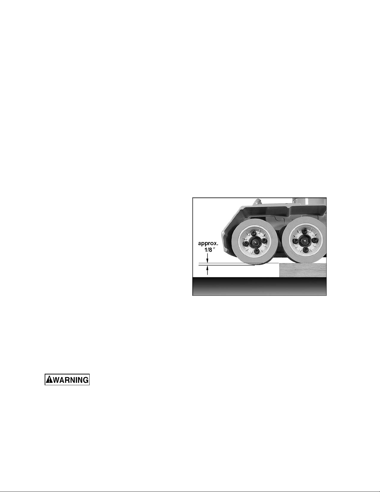
6. When used in horiz ontal position, t he stock
feeder should be adjusted f or height so that
the distance bet ween the table and the feed
rollers is approximately 1/8” (3mm) less than
the thickness of the workpiece. See Figure
17.
7. Shaping hardwood with the stock feeder
may increase the friction between workpiece
and table. Keep t he work tabl e rust-free and
smooth, by using paste wax or other
necessary means.
8. Various configurations are possible with
your Stock Feeder, depending upon your
auxiliary machine and the type of work
being done. What is important is that the
feeder is positioned in the most effective
and safest manner for the work being
done.
Although the stock feeder
when properly used will greatly reduce the
chance of wo rkpiece kickb ack, t here i s still a
potential for kickback. Never stand directly
in the path of the workpiece as it passes
under the stock feeder ro ll ers.
Figure 17
When Used with a Shaper
1. The gap between the fences for the cutter
should be as small as possible.
14
Page 15

2. To ensure that the workpiece is held firmly
against the f ence, set the stock f eeder at a
slight angl e toward the f ence i n the dir ecti on
of feed. In other words, the outfeed roller
should be approxim at ely 3/16” (5mm) cl oser
to the fence than the infeed roller. See
Figure 18.
3. When the Stock Feeder is in edgewise
position, it must be inclined slightly t owards
the work table in the direction of feed, to
ensure the workpi ece remains forced down
against the table. In other words, the
outfeed roll er should be a pprox im ately 3/16”
closer to the work table than the infeed
roller. S ee Figure 19.
4. When the Stock Feeder is in the edgewise
position, or angled for a beveled workpiece,
the axis of the cutter should be between the
infeed roller and the center roller (between
the two center rol lers on the 4-r oller model).
See Figure 19. The center roller should
NOT be directed toward the opening
between the f ences, but should act direc tly
against the fence.
Figure 18
(Stock Feeder in horizontal position)
5. When mounting the Stock Feeder in
edgewise posi tion, keep in mi nd the spring
tension of t he roller s. The distance bet ween
the shaper fence and t he f eed roller s should
be approximately 1/8” (3mm) less than the
thickness of the workpiece (refer to Figure
17).
When Used with a Table Saw
1. Position the 3-roller stock feeder so that the
axis of t he saw blade lines up bet ween the
center roll er and outfeed roller. (See Fi gure
20.) Position the 4-roller stock feeder so that
the axi s of the saw blade li nes up between
the center wheels. These positions will allow
the Stock Feeder to grip the offcut of the
workpiece as it leaves the blade.
2. Rotate the Stock Feeder so that the
direction of feed is angled slightly toward the
fence by approx im ately 3/16” (5mm) ; that i s,
the outfeed roll er shoul d be sli ghtly cl oser to
the fence t han the infeed roll er. See Figure
20.
Figure 19
(Stock Feeder in edgewise position)
Figure 20
When Used with a Jointer
1. Mount the 3-roller stock feeder on a j ointer
so that the cutterhead is between the
outfeed roller and the center roller (Figure
21). The 4-roller stock feeder can be
positioned so that the cutt erhead i s between
the center roller s.
Figure 21
15
Page 16

2. Some woodworkers prefer to place the
feeder so that all rollers are over the outfeed
table, as shown in Figure 22. The infeed
roller should be approximately 3/16” away
from the lip of the outfeed table at the
cutterhead area.
3. Rotate the Stock Feeder so that the
direction of feed is angled slightly toward the
fence by approx im ately 3/16” (5mm) ; that i s,
the outfeed roll er shoul d be sli ghtly cl oser to
the fence t han t he inf eed roll er. See Figur es
21 and 22.
Roller Removal/Replacement
If a f eed roller becomes worn or damaged i t is
easily replaced. Also, if more clearance is
needed between roll ers, the cent er roller can be
removed.
1. To remove a roller, lower the stock feeder
until it contacts the table of the auxiliary
machine – this will give you purchase for
loosening the screws with a 5mm hex
wrench. When the screws are loose, raise
the feeder off t he table to conti nue removing
the roller(s).
Figure 22
There are four screws i n each roll er: the t wo
short screws unite the halves of the roller
hub; the two long screws secure the roller
assembly to the feeder. You only need to
remove t he two long screws to remove the
roller assembly. NOTE: Replacement roller
assemblies m ay have a one-piece hub, and
thus the two short screws will no longer be
needed.) See Figure 23.
2. When a roll er assembly is re-mount ed to the
stock feeder, m ak e sure all screws are tight.
Maintenance
Before any intervention on
the machine, di sconnect it from the electrical
supply by pulling out the plug or switching
off the main switch. Failure to comply may
cause serious inj ury.
If the power cord is worn, cut, or damaged in
any way, have it repl ac ed immediately.
The rubber tires on the rollers should be kept
clean of grease, sawdust and other debris. Use
a soft cloth with soap and water to wipe down
the tires. DO NOT use a solvent on the rubber
tires.
Figure 23
The mating parts of the cones should be kept
clean. See Fi gure 24. When disassembling any
of the cones, wipe off both mating parts with a
clean rag befor e r e- assembling.
Figure 24
16
Page 17

NOTE: These cones are su bject to high torque
and it may be necessary to periodically retighten the handle until the cone surfaces
become securel y seated.
Exposed metal areas, such as the col umn and
the over arm, should be kept clean and f ree of
rust.
Lubrication
Oil Reservoir
Open the oil cap (shown in Figure 25). The oil
level should be approx imately 1-1/2” deep; that
is, about 1” f r om the rim of t he hol e. Peri odicall y
check the oil lev el and top off as needed with 90
weight gear oil.
Completely drain and refill the oil every 1,000
working hours, or ev er y 6 months.
To change the oil:
1. Remove the feeder body from the clamp.
2. Unscrew and remov e the oil cap (shown in
Figure 25) and t urn the feeder body upside
down to completely drain the oil. (NOTE:
Always dispose of used oi l pr oper ly.)
3. Turn feeder body right side up, and pour
new oil into the fill hole, until it is about 1”
from the rim.
Figure 25
4. Re-install the oil cap (Figure 25).
Rollers
NOTE: Grease is not provided with the grease
gun. To fill the grease gun, follow the
instructions on its package.
Each of t he r ollers has a grease fitting l ocated in
the hub center, as shown in Fi gure 26. Use the
provided grease gun to i nsert a good qualit y, allpurpose grease into these fittings every 200
working hours, or ev er y 30 days.
Also insert grea se into the fit ting on each tip of
the sprocket shaf t s, which are l ocat ed inside t he
housing cover as shown in Fi gur e 27.
Chains
Lubricate t he drive chains (shown in Fi gure 13)
with good quality all-purpose grease every 3
months, or more frequent ly if needed.
Elevating Screw
Occasionall y apply a light coat of gr ease to the
elevating screw of the vertical col umn (identifi ed
in Figure 1 on page 7).
Figure 26
Figure 27
17
Page 18

Troubleshooting
Trouble Probable Cause Remedy
Not connected t o power source. Check power connections.
Fuse blown, or cir c uit break er tr ipped. Replace fuse, or reset circuit breaker.
Feeder will not start .
Cord damaged. Replace cord.
Starting capacitor is malfunctioning. Replace starting capacitor.
Feed rate is not
suffic ien t; m a ch in e
has low power.
Workpiec e jam s or
moves sluggishl y
while passing
beneath roll ers.
Workpiece slips while
passing under rollers.
Gears installed incorrectly for the
desired feed r ate.
Extension cord too light or too long.
Low current fr om el ectri c al suppl y . Contact a qualified electrician.
Rollers too low. Raise feeder.
Rollers too high, no traction. Lower feeder.
Grease or debris on rubber t ir es. Clean ti res.
Install gears in pr oper posi tion. See
Figure 14.
Replace with adequat e si z e and
length cord. See Figure 10.
Replacement Parts
Replacement par ts are li sted on the f ollowing page s. To order parts or reac h our servi ce depar tm ent, call
1-800-274-6848, Monday through Friday (see our website for business hours, www.powermatic.com).
Having the Model Number and Serial Number of your mac hine available when you cal l will allow us to
serve you quickly and accurately.
18
Page 19

PF-31/33 Feeder Body
19
Page 20

Parts List: PF-31/33 Feeder Body
Index No. Part No . Description Size Qty
................. 2192188...................PF-31 Feeder Body (1Ph, 115V, 4 speed) ...............................................
................. 2192187...................PF-33 Feeder Body (3Ph, 230V, 4 speed) ...............................................
................. 2192189...................PF-33 Feeder Body (3PH, 460V, 4 speed) ...............................................
1 ............... 6289074...................Grease Gun ........................................................................................... 1
2 ............... 6289211...................Grease Fitting ........................................................................................ 3
3 ............... 6289212...................Roller Hub Spring .................................................................................. 3
4 ............... 6288938A ................Tube ...................................................................................................... 3
5 ............... 6289125A ................Sprocket Shaft ....................................................................................... 2
6 ............... JPF3-041A ...............Case Cover ........................................................................................... 3
7 ............... 6288750...................Socket Head Cap Screw .....................................M8 x 1.25P x 40Lg ...... 6
8 ............... 6288764...................Star Washer .......................................................M8 ............................ 12
9 ............... 6289116...................Rollers – set of 3 only .........................................Ø120 x 60mm ............. 1
................. 6288959...................Roller (individual) ................................................Ø120 x 60mm ............. 3
10 ............. 6288749...................Socket Head Cap Screw .....................................M8 x 20 Lg ................. 6
11 ............. 6289129...................Grease Nipple ....................................................................................... 3
12 ............. 6289130...................Shaft ..................................................................................................... 3
13 ............. 6289121...................Roller Supporter .................................................................................... 3
14 ............. 6288949...................Chain Kit ............................................................26S ............................ 3
15 ............. 6288944...................Sprocket ................................................................................................ 3
16 ............. 6289122...................Star Wash er .......................................................M6 .............................. 6
17 ............. 6289123...................Cap Screw..........................................................M6 x 1.0P x 16 Lg....... 6
18 ............. 6288751A ................Sprocket Case (PF-31/33) ..................................................................... 3
19 ............. 6289131
21 ............. 6289126A ................Sprocket Shaft ....................................................................................... 1
24 ............. 6289228...................Frame.................................................................4SP 1Ph ..................... 1
................. 6289229...................Frame.................................................................4SP 3Ph ..................... 1
25 ............. 6289139...................Back Cover ............................................................................................ 1
26 ............. 6289136...................Set Screw ...........................................................M6 x 1.0P x 10Lg........ 3
27 ............. 6288980...................Oil Cap .................................................................................................. 1
28 ............. 6288979..................."O" Ring ................................................................................................ 1
29 ............. 6288955...................Snap Ring ..........................................................Ø2 6mm ...................... 3
30 ............. 6288954...................Chain .................................................................4 0 S ............................ 2
31 ............. 6288975...................Chain .................................................................6 2 S ............................ 1
32 ............. 6289092...................Sprocket w/Key ..................................................................................... 2
33 ............. 6288958...................Snap Ring ..........................................................Ø1 5mm ...................... 2
37 ............. 6289093...................Sprocket w/Key ..................................................................................... 2
38 ............. 6289097...................Gear ...................................................................40T............................. 1
39 ............. 6289127...................Lock Was h e r ......................................................M12 ............................ 1
40 ............. 6289128...................Nut .....................................................................M12 x 1.75 ................. 1
41 ............. 6289201...................Bushing ................................................................................................. 1
42 ............. 6289197...................Gear ...................................................................................................... 1
43 ............. 6288965...................Bearing...............................................................#6203 ......................... 1
44 ............. 6288969...................Oil Seal ................................................................................................. 1
45 ............. 6289146...................Cap Screw..........................................................M5 x 0.8P x 16Lg........ 4
46 ............. 6289096...................Gear w/Key ........................................................25T............................. 1
47 ............. 6289140...................Knob Assembly ..................................................................................... 2
48 ............. 6289198...................Nut .....................................................................M12 x 1.75 ................. 1
49 ............. 33-6004-00-2 ...........Spring Wash er....................................................M12 ............................ 1
50 ............. 6289145...................Cover .................................................................................................... 1
51 ............. 6289144..................."O" Ring ................................................................................................ 1
52 ............. 6289205
53 ............. 6289204...................Gear ...................................................................17T............................. 1
54 ............. 6289202...................Gear ...................................................................38T............................. 1
55 ............. 6289203...................Gear ...................................................................31T............................. 1
58 ............. 6289061...................Gear ...................................................................34T............................. 1
59 ............. 6289142...................Shaft ..................................................................................................... 1
60 ............. 6289058...................Clutch .................................................................................................... 1
...................Lock Was h e r ......................................................M12 ............................ 3
...................Bushing ................................................................................................. 1
20
Page 21

Index No. Part No . Description Size Qty
61 ............. 6289057...................Gear ...................................................................20T............................. 1
62 ............. 6289056...................Bushing ..............................................................20D x 17D x (10+2) .... 1
63 ............. 6289135...................Bushing ..............................................................29D x 23D x (9+3) ...... 1
64 ............. 6289153...................Gear Lever Shaft ................................................................................... 1
65 ............. 6289070...................Ball ........................................................................................................ 1
66 ............. 6289071...................Spring .................................................................................................... 1
67 ............. 6289149...................Transmission Lever ............................................................................... 1
68 ............. 6289150...................Star Wash er .......................................................................................... 1
69 ............. 6288763...................Cap Screw..........................................................M5 x 0.8P x 12Lg........ 1
70 ............. 6289154...................Cap Screw..........................................................M5 x 0.8P x 10Lg........ 2
71 ............. 6289067..................."O" Ring ................................................................................................ 1
72 ............. 6289148...................Lock Pin .............................................................Ø4 x 20mm ................. 1
73 ............. 6289147...................Gear Lever ............................................................................................ 1
74 ............. 6289152..................."O" Ring ................................................................................................ 1
77 ............. 6288755...................Snap Ring ..........................................................20mm ......................... 3
78 ............. 6288756...................Hex Screw ..........................................................M12 x 1.75P x 75Lg .... 3
79 ............. 6288757...................Key.....................................................................6 x 6 x 18 mm ............. 1
80 ............. 6288758...................Worm Gear Shaft................................................................................... 1
81 ............. 6288759...................Snap Ring ..........................................................Ø2 2mm ...................... 1
82 ............. 6288760..................."O" Ring ................................................................................................ 1
83 ............. 6288761...................Cap ....................................................................................................... 1
84 ............. 6288762...................Cap Screw..........................................................M5 x 0.8P x 12Lg........ 2
21
Page 22

PF-41/43 Feeder Body
22
Page 23

Parts List: PF-41/43 Feeder Body
Index No. Part No . Description Size Qty
................. 2192190...................PF-43 Feeder Body (3Ph, 230V, 4 speed) ...............................................
................. 2192191...................PF-41 Feeder Body (1Ph, 230V, 4 speed) ...............................................
1 ............... 6289074...................Grease Gun ........................................................................................... 1
2 ............... 6289211...................Grease Fitting ........................................................................................ 4
3 ............... 6289212...................Roller Hub Spring .................................................................................. 4
4 ............... 6288938A ................Tube ...................................................................................................... 4
5 ............... 6289125A ................Sprocket Shaft ....................................................................................... 3
6 ............... JPF3-041A ...............Case Cover ........................................................................................... 4
7 ............... 6288750...................Socket Head Cap Screw .....................................M8 x 1.25 P x 40Lg ...... 8
8 ............... 6288764...................Star Washer .......................................................M8 ............................ 16
9 ............... 6289118...................Rollers – set of 4 only .........................................Ø120 x 60mm ............. 1
................. 6288959...................Roller (individual) ................................................Ø120 x 60mm ............. 4
10 ............. 6288749...................Socket Head Cap Screw .....................................M8 x 20 ...................... 8
11 ............. 6289129...................Grease Nipple ....................................................................................... 4
12 ............. 6289130...................Shaft ..................................................................................................... 4
13 ............. 6289121...................Roller Supporter .................................................................................... 4
14 ............. 6288949...................Chain Kit ............................................................26S ............................ 4
15 ............. 6288944...................Sprocket ................................................................................................ 4
16 ............. 6289122...................Star Wash er .......................................................M6 .............................. 8
17 ............. 6289123...................Cap Screw..........................................................M6 x 1.0P x 16Lg........ 8
18 ............. 6288751A ................Sprocket Case (PF-31/33/41/43)............................................................ 4
19 ............. 6289131...................Lock Was h e r ......................................................M12 ............................ 4
21 ............. 6289126A
24 ............. 6289133...................Frame.................................................................4SP 1Ph ..................... 1
................. 6289134...................Frame.................................................................4SP 3Ph ..................... 1
25 ............. 6289109...................Back Cover ............................................................................................ 1
26 ............. 6289136...................Set Screw ...........................................................M6 x 1.0P x 10Lg........ 4
27 ............. 6288980...................Oil Cap .................................................................................................. 1
28 ............. 6288979..................."O" Ring ................................................................................................ 1
29 ............. 6288955...................Snap Ring ..........................................................Ø2 6mm ...................... 4
30 ............. 6288954...................Chain .................................................................4 0 S ............................ 2
31 ............. 6288975...................Chain .................................................................6 2 S ............................ 1
32 ............. 6289092...................Sprocket w/Key ..................................................................................... 2
33 ............. 6288958...................Snap Ring ..........................................................Ø1 5mm ...................... 4
37 ............. 6289093...................Sprocket w/Key ..................................................................................... 2
38 ............. 6289097...................Gear ...................................................................40T............................. 1
39 ............. 6289127...................Lock Was h e r ......................................................M12 ............................ 1
40 ............. 6289128...................Nut .....................................................................M12 x 1.75 ................. 1
41 ............. 6289201...................Bushing ................................................................................................. 1
42 ............. 6289197...................Gear ...................................................................................................... 1
43 ............. 6288965...................Bearing...............................................................#6203 ......................... 1
44 ............. 6288969...................Oil Seal ................................................................................................. 1
45 ............. 6289146...................Cap Screw..........................................................M5 x 0.8P x 16Lg........ 4
46 ............. 6289096...................Gear ...................................................................25T............................. 1
47 ............. 6289140...................Knob Assembly ..................................................................................... 2
48 ............. 6289198...................Nut .....................................................................M12 ............................ 1
49 ............. 33-6004-00-2 ...........Spring Wash er....................................................M12 ............................ 1
50 ............. 6289145...................Cover .................................................................................................... 1
51 ............. 6289144..................."O" Ring ................................................................................................ 1
52 ............. 6289205...................Bushing ................................................................................................. 1
53 ............. 6289204
54 ............. 6289202...................Gear ...................................................................38T............................. 1
55 ............. 6289203...................Gear ...................................................................31T............................. 1
58 ............. 6289061...................Gear ...................................................................34T............................. 1
59 ............. 6289142...................Shaft ..................................................................................................... 1
60 ............. 6289058...................Clutch .................................................................................................... 1
61 ............. 6289057...................Gear ...................................................................20T............................. 1
................Sprocket Shaft ....................................................................................... 1
...................Gear ...................................................................17T............................. 1
23
Page 24

Index No. Part No . Description Size Qty
62 ............. 6289056...................Bushing ..............................................................20D x 17D x (10+2) .... 1
63 ............. 6289135...................Bushing ..............................................................29D x 23D x (9+3) ...... 1
64 ............. 6289153...................Gear Lever Shaft ................................................................................... 1
65 ............. 6289070...................Ball ........................................................................................................ 1
66 ............. 6289071...................Spring .................................................................................................... 1
67 ............. 6289149...................Transmission Lever ............................................................................... 1
68 ............. 6289150...................Star Wash er .......................................................................................... 1
69 ............. 6288763...................Cap Screw..........................................................M5 x 0.8P x 12Lg........ 1
70 ............. 6289154...................Cap Screw..........................................................M5 x 0.8P x 10Lg........ 2
71 ............. 6289067..................."O" Ring ................................................................................................ 1
72 ............. 6289148...................Lock Pin .............................................................Ø4 x 20mm ................. 1
73 ............. 6289147...................Gear Lever ............................................................................................ 1
74 ............. 6289152..................."O" Ring ................................................................................................ 1
77 ............. 6288755...................Snap Ring ..........................................................Ø2 0mm ...................... 4
78 ............. 6288756...................Hex Screw ..........................................................M12 x 1.75P x 75Lg .... 4
79 ............. 6288757...................Key.....................................................................6 x 6 x 18 mm ............. 1
80 ............. 6288758...................Worm Gear Shaft................................................................................... 1
81 ............. 6288759...................Snap Ring ..........................................................Ø2 2mm ...................... 1
82 ............. 6288760..................."O" Ring ................................................................................................ 1
83 ............. 6288761...................Cap ....................................................................................................... 1
84 ............. 6288762...................Cap Screw..........................................................M5 x 0.8P x 12Lg........ 2
24
Page 25

Parts List: Motor Assembly for PF-31/33 and PF-41/43
SINGLE PHASE
Index No. Part No . Description Size Qty
1 ............... 6289098...................Motor ..................................................... 1HP, 1Ph, 115V, 60Hz ............ 1
2 ............... 6289207..................."O" Ring ................................................ ............................................... 1
3 ............... 6289086...................Screw .................................................... M8 x 1.25P x 20Lg .................. 4
4 ............... 6289085...................Lock Washer ......................................... ............................................... 4
5 ............... 6289115...................Control Switch ....................................... ............................................... 1
6 ............... 6289087...................Capacitors (set of 2) .............................. ............................................... 1
...............................Start Capacitor ...................................... 200MF D 125V A C .................... 1
...............................Run Capacitor ....................................... 25 μF 250VAC ......................... 1
THREE PHASE
Index No. Part No . Description Size Qty
1 ............... 6289099...................Motor ..................................................... 1HP, 3Ph, 460V, 60Hz ............ 1
................. 6288988...................Motor ..................................................... 1HP, 3Ph, 230V, 60Hz ............ 1
2 ............... 6289207..................."O" Ring ................................................ ............................................... 1
3 ............... 6289086...................Screw .................................................... M8 x 1.25P x 20Lg .................. 4
4 ............... 6289085...................Lock Washer ......................................... ............................................... 4
5 ............... 6289003...................Control Switch ....................................... ............................................... 1
25
Page 26

Feeder Mounting Assembly for PF-31/33 and PF-41/43
26
Page 27

Parts List: Feeder Mounting Assembly for PF-31/33 and PF-41/43
Index No. Part No . Description Size Qty
................. 6289113...................Complete Mounting Base Assembly.........................................................
1 ............... 6289179...................Handle Assembly................................................M12 x 1.75 ................. 3
2 ............... 6288903...................Flat Washer ........................................................1/2 x 25 ...................... 3
3 ............... 6289178...................Stud ...................................................................M12 x 70 m m .............. 3
4 ............... 6289177...................Column Base ......................................................................................... 1
5 ............... 6289210...................Nut .....................................................................M8 x 1.25 ................... 1
6 ............... 6289200...................Spring Washe r....................................................M8 .............................. 1
7 ............... 6289188...................Set Screw ...........................................................M8 x 1.25P x 20Lg ...... 1
8 ............... 6289163...................Rack ...................................................................................................... 1
9 ............... 6289164...................Cap Screw..........................................................M5 x 0.8P x 10Lg........ 4
10 ............. 6288923...................Over Arm ............................................................720mm ....................... 1
11 ............. 6289219...................Vertical Column ..................................................560mm ....................... 1
12 ............. 6289174...................Set Screw ...........................................................M8 x 1.25P x 12Lg ...... 3
13 ............. 6289173...................Column Cap .......................................................................................... 1
14 ............. 6289222...................Thrus t Was h er ....................................................................................... 2
15 ............. 6289220...................Elevating Screw ..................................................................................... 1
16 ............. 6289161...................Elevating Key ........................................................................................ 1
17 ............. 6289162...................Cap Screw..........................................................M5 x 0.8P x 16Lg........ 1
18 ............. 6289181...................Over Arm Cone ..................................................................................... 1
19 ............. 6288930...................Spring Was he r....................................................M10 ............................ 2
20 ............. 6289183...................Bolt.....................................................................M10 x 1.5P x 50Lg ...... 2
21 ............. 6289180...................Elevating Bracket................................................................................... 1
22 ............. 6288912...................Pinion .................................................................M8 x 1.25P x 12Lg ...... 3
23 ............. 6288913...................Handw
24 ............. 6289166...................Lock Pin .............................................................6 x 36 ......................... 1
25 ............. 6288926...................Handle Assembly................................................................................... 2
26 ............. 6288927...................Lock Pin .............................................................6 x 22 ......................... 2
27 ............. 6289176...................Wheel Handle .....................................................M10 x 1.5 ................... 1
28 ............. 6289221...................Pin......................................................................6 x 36 ......................... 1
29 ............. 6289175A ................Elevating Handle ................................................................................... 1
30 ............. 6289222...................Thrus t Was h er ....................................................................................... 1
31 ............. 6289182...................Lock Stud ...........................................................M16 x 1.5 ................... 2
32 ............. 6289168...................Swivel Cone .......................................................................................... 1
33 ............. 6289169...................Motor Clamp .......................................................................................... 1
34 ............. 6289170...................Bolt.....................................................................M8 x 1.25 P x 50Lg ...... 1
35 ............. 6288887...................Locking Handle ...................................................................................... 1
36 ............. TS-1492051 .............Hex Cap Screw (not shown) ...............................M12 x 50 .................... 4
37 ............. TS-2361121 .............Spring Washer (not shown) ................................M12 ............................ 4
heel ............................................................................................ 1
27
Page 28

Electrical Connections – 3 Phase only
GROUND
Red (4)
Red (6)
White (1)
White (2)
Red (5)
White (3)
2
6
10
14
z
18
22
R
S
T
R
1
S
5
W
9
X
13
17
T
21
3
4
7
8
U
11
12
Y
15
16
19
20
V
23
24
427 New Sanford Road
LaVergne, Tennessee 37086
Phone: 800-274-6848
www.powermatic.com
28
 Loading...