


Powerex MPD0758, MPQ, MPD1508, MPD1008, MPD0508 User Manual
...
P U R E |
A I R |
T E C H N O L O G Y |
|
|
|
GENERAL PRODUCT MANUAL |
|
Medical Package System |
|
|
|
Please read and save these instructions. Read carefully before attempting to assemble, install, operate or maintain the product described. Protect yourself and others by observing all safety information. Failure to comply with instructions could result in personal injury and/or property damage! Retain instructions for future reference.
Description
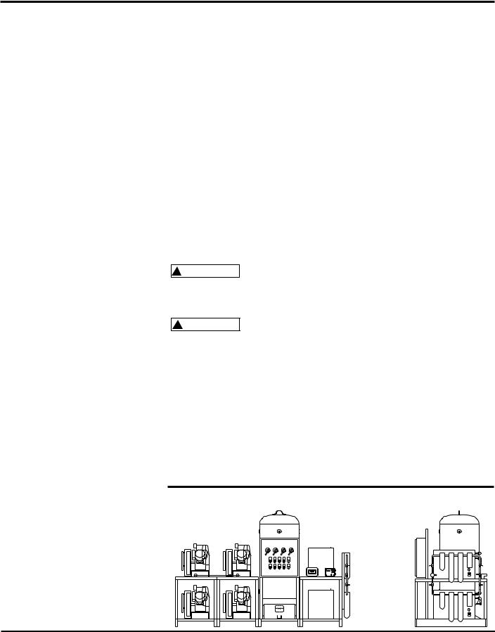
The Powerex medical system package is designed to provide medical breathing air for hospital and medical institutes.
This system meets NFPA 99 requirements for Level 1 breathing air.
OILLESS OPT/OPS COMPRESSOR
The Powerex oilless reciprocating air compressor has advanced compressor technology through the development of a completely oilless compressor. The Powerex reciprocating compressor is provided in duplex, triplex or quadplex configurations with head unloaders to provide start, stop or continuous operation. Composite piston technology and continuously lubricating bearings provide oil-free air reliability for years to come.
RECEIVER TANK
The ASME, National Board registered air receiver is provided in sizes from 120 to 240 gallons. Each receiver is rated at 200 PSIG working pressure. Receivers are provided with sight glass and moisture drain (manual or automatic).
CONTROL PANEL
The NEMA 12 control panel is provided in duplex, triplex or quadplex configurations and meets NFPA 99 requirements for medical air. Primary voltage is protected by fusing or circuit breaker. Control transformer power is 110 volts and protected by secondary fusing. Pressure control switches signal the compressors on and off cycle and signal lag compressor(s) to come on if air demand increases. A lag, lag pressure switch or transducer signals a light and audible alarm warning of a low pressure condition which is factory set at 40 PSIG. An acknowledge button is provided for start condition and maintenance. The adjustable timer alternator cycles each compressor so equal run time is maintained. This alternator is factory set to alternate the compressors every 10 minutes. The exterior of the control panel is accessible through the door. The panel disconnects on/off/auto switches run lights, power on lights, run hourmeters, lag pressure light, high
temperature light and overload reset. This control panel is UL listed.
DEW POINT MONITOR
The Powerex dew point monitor provides indication of dew point and temperature. It’s microprocessor controlled with user programmable output range, alarm and calibration. The NEMA enclosure is protected by a polymer viewing cover.
CARBON MONOXIDE MONITOR/ALARM
The carbon monoxide monitor provides warning to the user of air-supplied respirators alarming and metering the presence of carbon monoxide. The monitor is provided in a NEMA 12 enclosure. In addition to audio/visual alarm, the meter displays the concentration of CO in the compressed air. The meter operates from a 110 VAC supply. Alarm points are set a 10PPM (low) and 20 PPM (high).
AIR COOLED AFTERCOOLER
Four models of beltguard aftercoolers sized to provide an approach of 20°F. Constructed of copper tubing and metal headers for a rugged construction.
AIR DRYER (REFRIGERATED OR DESICCANT)
The Powerex air drying system provides air at 38°F at 100 PSIG for refrigerated units and -40°F dew point for desiccant dryer systems. Each system is connected with bypass capability.
The refrigerated compressed air dryer(s) are noncycling, direct expansion type, using R-22 refrigerant,
CFC free. A hot gas bypass valve is provided to maintain 38°F evaporator temperature. The dryer is selfregulating for large load swings. Heat exchangers are made of copper tube construction and insulated.
The regenerative desiccant consists of two (dual) towers filled with desiccant. Each tower is switched on and off stream, alternating the air system stream and then being regenerated. Dry purge air pulls moisture from the desiccant and carries the moisture out of the air.
MEDICAL FILTER SYSTEM
The medical filter system consists of a duplex series of filters and pressure regulators. Air enters the system and is directed to either bank of filets controlled by ball valve. The first stage filter removes solids and liquid particles. The next stage of filters remove submicronic particles and aerosols. The third and final filter is carbon activated to remove unpleasant odors. Maximum operating temperature is 125°F and maximum pressure is 150 PSIG.
CONDENSATE DRAIN VALVE
A condensate drain valve must be installed on any tank. This valve removes liquid that collects during compressor operation.
Drain liquid from tank daily.
Safety Guidelines
This manual contains information that is very important to know and understand. This information is provided for SAFETY and to PREVENT EQUIPMENT PROBLEMS.
Powerex • 150 Production Drive • Harrison, OH 45030 • USA |
IN259200AV 11/00 |
Medical Package System
To help recognize this information, observe the following symbols.
Danger indicates ! DANGER an imminently
hazardous situation which, if not avoided, will result in death or serious injury.
! WARNING |
Warning indicates |
|
a potentially |
||
|
||
hazardous situation which, if not |
||
avoided, could result in death or |
||
serious injury. |
|
|
|
Caution indicates a |
|
! CAUTION |
||
potentially |
||
hazardous situation which, if not |
||
avoided, MAY result in minor or |
||
moderate injury. |
|
|
|
Notice indicates |
|
NOTICE |
||
important |
||
|
||
information that, if not followed, may cause damage to equipment.
Unpacking
RECEIVING THE UNIT
Immediately upon receipt of the oilless compressor, inspect for any damage which may have occurred during shipment.
The compressor nameplate should be checked to verify the correct model and voltage as ordered.
|
Do not operate |
|
! WARNING |
||
unit if damaged |
||
|
||
during shipping, handling or use. |
||
Damage may result in bursting and |
||
cause injury or property damage. |
||
General Safety Information
The following safety precautions must be observed at all times:
1. Read all manuals |
|
|
|
included with this |
|
|
|
|
|
||
product carefully. Be |
|
MANUAL |
|
thoroughly familiar with |
|
|
|
the controls and the |
|
|
|
|
|
|
|
proper use of the equipment. |
|
|
|
2.Follow all local electrical and safety codes, as well as in the United States, the National Electrical Codes (NEC) and Occupational Safety and Health Act (OSHA).
3.Only persons well acquainted with these rules of safe operation should be allowed to use the equipment.
4.Keep visitors away and NEVER allow children in the work area.
5.Wear safety glasses and use hearing protection
when operating the unit.
6.Do not stand on or use the unit as a handhold.
7.Before each use, inspect compressed air system and electrical components for signs of damage, deterioration, weakness or leakage. Repair or
replace defective items before using.
8.Check all fasteners at frequent intervals for proper tightness.
! WARNING
Electrical equipment and controls can cause
electrical arcs that will ignite a flammable gas or vapor. Never operate or
repair in or near a flammable gas or vapor. Never store flammable liquids or gases in the vicinity of the compressor.
An ASME code safety relief valve,
with a setting no higher than the tank maximum allowable working pressure, MUST be installed in the air lines or in the tank. The ASME safety valve must have sufficient flow and pressure ratings to protect the pressurized components from bursting. The flow rating can be found in the parts manual.
Do not operate ! CAUTION with pressure
switch or pilot valves set higher than the tank maximum allowable working pressure.
9.Never attempt to adjust ASME safety valve. Keep safety valve free from paint and other accumulations.
!DANGER
Never attempt to repair or modify a tank! Welding, drilling or any other
modification will weaken the tank resulting in damage from rupture or explosion. Always replace worn, cracked or damaged tanks.
|
Drain liquid from |
|
NOTICE |
||
tank daily. |
||
|
10.Tanks rust from moisture build-up, which weakens the tank. Make sure to drain tank regularly and inspect periodically for unsafe conditions such as rust formation and corrosion.
11.Fast moving air will stir up dust and debris which may be harmful. Release air slowly when draining moisture or depressurizing.
Installation
! WARNING
Disconnect, tag and lock out power source then release all pressure from
the system before attempting to install, service, relocate or perform any maintenance.
Do not lift or move ! CAUTION unit without
appropriately rated equipment. Be sure the unit is securely attached to lifting device used. Do not lift unit by holding onto tubes or coolers. Do not use unit to lift other attached equipment.
Installation of inlet/outlet air
plumbing from the compressor flange and eletrical connection must be in accordance with National Fire Protection Association (NFPA99) Code Compliance for Medical Gas Breathing Air (Level 1).
INSTALLATION SITE
1.The oilless compressor must be located in a clean, well lit and well ventilated area.
2.The area should be free of excessive dust, toxic or flammable gases and moisture.
3.Never install the compressor where the surrounding temperature is higher than 105o F or where humidity is high.
4.Clearance must allow for safe, effective inspection and maintenance.
Minimum Clearances
Above 24”
Other sides |
36” |
5.If necessary, use metal shims or leveling pads to level the compressor. Never use wood to shim the compressor.
VENTILATION
1.If the oilless compressor is located in a totally enclosed room, an exhaust fan with access to outside air must be installed.
2.Never restrict the cooling fan exhaust air. Maintain a minimum of 3 feet of clearance around entire unit.
3.Never locate the compressor where hot exhaust air from other heat generating units may be pulled into the unit.
WIRING
All electrical hook-ups must be performed by a qualified electrician. Installations must be in accordance with local and national electrical codes.
Use solderless terminals to connect the electric power source.
PIPING
Refer to the general product manual.
1.Make sure the piping is lined up without being strained or twisted when assembling the piping for the compressor.
2.Appropriate expansion loops or bends should be installed at the
2
Medical Package System
compressor to avoid stresses caused by changes in hot and cold conditions.
3.Piping supports should be anchored separately from the compressor to reduce noise and vibration.
4.Never use any piping smaller than the compressor connection.
5.Use flexible hose to connect the outlet of the compressor to the piping so that the vibration of the compressor does not transfer to the piping.
SAFETY VALVES
Tank mounted compressors are shipped from the factory with safety valves installed in the tank manifold. The flow capacity of the safety valve is equal to or greater than the capacity of the compressor.
1.The pressure setting of the safety valve must be no higher than the maximum working pressure of the tank.
2.Safety valves should be placed ahead of any possible blockage point in the system, i.e. shutoff valve.
3.Avoid connecting the safety valve with any tubing or piping.
4.Manually operate the safety valve every six months to avoid sticking or freezing.
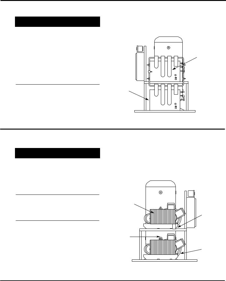
Assembling Modular
Medical System
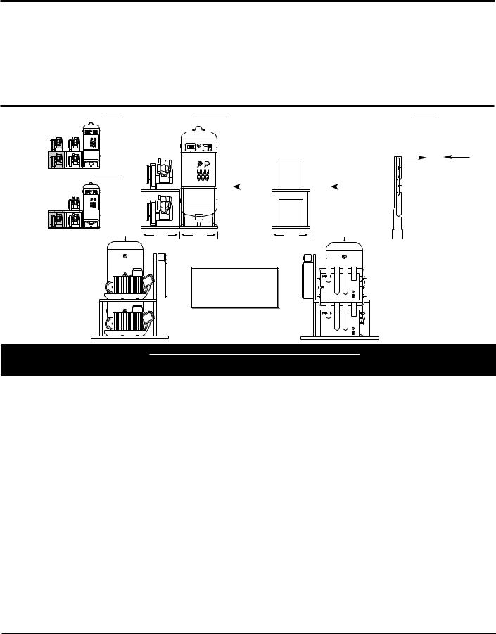
MODULAR PLACEMENT
1.Unpack each module and discard all wood shipping materials.
2.Locate frame assembly fasteners provided in parts pack [includes: fasteners, filter(s), isolation pads and inlet flex line].
3.Place modules at location designated (see picture below for proper arrangment of modules). Provide sufficient clearance around unit for servicing (see minimum clearance section).
4.Install frame assembly fasteners to each frame joining the frames together.
5.Lift corners of each frame assembly and install isolation pads provided.
NOTE: Remove shipping brackets painted orange located at the base plate of each compressor module. This will allow spring isolators to free up reducing noise and vibration of the unit.
CONNECTING PIPING
1.Locate connection for piping at rear of unit for compressors module to receiver tank module.
2.Remove plastic caps that protect piping against contamination.
3.Connect flex joint to frame securely making sure flex line is not pinched or chinked.
4.Follow steps 1 to 3 for flex line from dryer package to outlet of receiver tank.
NOTE: All piping is provided and sealed for this portion of installation.
5.Locate and attach intake inline air filter to outside source air or header. Flex line is provided when attaching intake of compressors to rigid piping.
6.Connect outlet souce from filter package located on dryer module to outlet source piping.
Attach all inlet and ! WARNING outlet source
piping in accordance with NFPA 99 for Medical Gas.
ELECTRICAL WIRING OF MODULES
Provide electrical ! CAUTION power in accor-
dance to NEC and local codes. Connection of wiring should be performed by a qualified electrician.
1.Connect wiring and flex conduit provided from each motor junction box to correct hole in bottom of control panel and starter.
2.Connect each temperature switch from the compressors to contacts located in control panel as marked for each temperature switch. Temperature switches shutdown the
compressor when temperature is above 400°F.
3.Connect wiring of unload solenoids to contacts located on control panel. The unload solenoid provides loadless starting of the compressors on off cycle.
4.Connect wiring from differential pressure switch at control panel. Differential switch wired to contacts in control panel provided for remote alarm.
5.Connect wiring from CO Monitor. A wire set is provided for power and the other for alarm. Wiring is marked for easy attachment.
6.Connect wiring from Dew Point Monitor. A wire set is provided for power and the other for alarm. Wiring is marked for easy attachment.
7.Dryer(s) need a separate properly protected power supply for each dryer. Standard voltage is 110 Volts. Other voltages are available. Check for voltage of dryer supplied and current rating provided on data plate of dryer.
NOTE: Units provided with desiccant drying systems are wired directly to the control panel provided.
For questions concerning assembling and start-up, contact Powerex at 1-800- 544-0350 for technical assistance.
Operation
Powerex package medical system operates at a maximum pressure of 100 PSIG. Compressor RPM’s are established by Powerex based on horsepower and operating pressure.
MPD Medical
Package System
3

Medical Package System
BEFORE START UP
1.Make sure all safety warnings, labels and instructions have been read and understood before continuing.
2.Remove any shipping materials, brackets, etc.
3.Confirm that the electric power source and ground have been firmly connected.
4.Be sure all pressure connections are tight.
5.Check to be certain all safety relief valves, etc., are correctly installed.
6.Check that all fuses, circuit breakers, etc., are the proper size.
7.Make sure the inlet filter is properly installed.
8.Confirm that the drain valve is closed.
9.Visually check the rotation of the compressor pump. If the rotation is
incorrect, have a qualified electrician correct the motor wiring.
START-UP AND OPERATION
1.Follow all the procedures under
“Before start-up” before attempting operation of the compressor.
2.Switch the electric source breaker on.
3.Both dryers should be plugged in and set at the on position.
4.Dewpoint & CO Monitors should be on and the sampling valves open. Calibrate Dewpoint and CO per enclosed manufacturer’s instructions.
5.Ensure water lines are properly installed to water-cooled aftercoolers. Turn on water.
IMPORTANT: This is not a standard option. Check to see if water-
cooled aftercoolers were provided.
6.Compressor unit isolation valves are preset at the factory in the open position except for tank by-pass which must remain closed during normal operation.
7.Dryer and filter isolation valves: Valves should be open to one dryer and one filter bank.
8.Close valve leading to the Medical Air System from receiver on the compressor unit.
a.Turn both fusible/breaker disconnects to the on position. Low pressure alarm will sound. Silence the alarm by pushing alarm acknowledge button.
b.Jog each compressor in the manual position on the selector switch to check for rotation. (Clockwise if
Medical
Air Schematic
Specifications
Medical Package Duplex – Model MPD
MODEL |
HP |
PHASE |
SCFM |
SCFM |
RPM |
VOLTAGE |
FULL LOAD AMP/ |
GALLON |
DIMENSION |
SHIPPING |
@100 PSIG |
@ 50 PSIG |
MOTOR |
TANK |
LxWxH |
WT. (Lbs.) |
|||||
MPD0508 |
5(2) |
3 |
33.4 |
36.2 |
870 |
208/230/460 |
17.4 / 16.5 / 8.2 |
120 |
64 x 65 x 76 |
1288 |
|
|
|
|
|
|
|
|
|
|
|
MPD0758 |
7.5(2) |
3 |
52.2 |
55.1 |
840 |
208/230/460 |
23.4 / 22 / 11 |
120 |
64 x 65 x 76 |
1340 |
|
|
|
|
|
|
|
|
|
|
|
MPD1008 |
10(2) |
3 |
70 |
76.3 |
1070 |
208/230/460 |
29 / 33 / 16.5 |
200 |
64 x 65 x 80 |
1510 |
|
|
|
|
|
|
|
|
|
|
|
MPD1508 |
15(2) |
3 |
108.4 |
114.1 |
1250 |
208/230/460 |
51 / 48 / 24 |
200 |
64 x 65 x 80 |
1630 |
|
|
|
|
|
|
|
|
|
|
|
Medical Package Triplex – Model MPT
MODEL |
HP |
PHASE |
SCFM |
SCFM |
RPM |
VOLTAGE |
FULL LOAD AMP/ |
GALLON |
DIMENSION |
SHIPPING |
@100 PSIG |
@ 50 PSIG |
MOTOR |
TANK |
LxWxH |
WT. (Lbs.) |
|||||
MPT0508 |
5(3) |
3 |
50.1 |
54.7 |
870 |
208/230/460 |
17.4 / 16.5 / 8.2 |
200 |
96 x 65 x 80 |
1838 |
|
|
|
|
|
|
|
|
|
|
|
MPT0758 |
7.5(3) |
3 |
78.8 |
83.9 |
840 |
208/230/460 |
23.4 / 22 / 11 |
200 |
96 x 65 x 80 |
1980 |
|
|
|
|
|
|
|
|
|
|
|
MPT1008 |
10(3) |
3 |
105 |
111.5 |
1070 |
208/230/460 |
29 / 33 / 16.5 |
240 |
96 x 65 x 92 |
2160 |
|
|
|
|
|
|
|
|
|
|
|
MPT1508 |
15(3) |
3 |
162.6 |
168 |
1250 |
208/230/460 |
51 / 48 / 24 |
240 |
96 x 65 x 92 |
2280 |
|
|
|
|
|
|
|
|
|
|
|
Medical Package Quadplex – Model MPQ
|
MODEL |
HP |
PHASE |
SCFM |
SCFM |
RPM |
VOLTAGE |
FULL LOAD AMP/ |
GALLON |
DIMENSION |
SHIPPING |
|
|
@100 PSIG |
@ 50 PSIG |
MOTOR |
TANK |
LxWxH |
WT. (Lbs.) |
|
|||||
|
MPQ0508 |
5(4) |
3 |
66.8 |
74.9 |
870 |
208/230/460 |
17.4 / 16.5 / 8.2 |
240 |
128 x 65 x 92 |
2388 |
|
|
|
|
|
|
|
|
|
|
|
|
|
|
|
MPQ0758 |
7.5(4) |
3 |
104.4 |
120.2 |
840 |
208/230/460 |
23.4 / 22 / 11 |
240 |
128 x 65 x 92 |
2490 |
|
|
|
|
|
|
|
|
|
|
|
|
|
|
|
MPQ1008 |
10(4) |
3 |
140 |
153 |
1070 |
208/230/460 |
29 / 33 / 16.5 |
240 |
128 x 65 x 92 |
2640 |
|
|
|
|
|
|
|
|
|
|
|
|
|
|
|
MPQ1508 |
15(4) |
3 |
216.8 |
221 |
1250 |
208/230/460 |
51 / 48 / 24 |
240 |
128 x 65 x 92 |
2735 |
|
|
|
|
|
|
|
|
|
|
|
|
|
|
|
|
|
|
|
|
|
|
|
|
|
|
|
4
Medical Package System
facing the black fan shroud and counterclockwise if facing the compressor flywheel.)
c.Set both selector switches to the auto position. Compressors will both run until the lead pressure switch closes.
d.Open valve at the air receiver leading to Medical Air System.
e.Check for air leaks at the connections.
9.Check that the compressor operates without excessive vibration, unusual noises or leaks.
10.Check the discharge pressure. Also make sure the air pressure rises to the designated pressure setting by checking the discharge pressure gauge.
11.Check the operation of the pressure switch or the pilot valve for continuous run units by opening the stop valve and confirming the compressor starts or reloads as pressure drops.
QUADPLEX MPQ
TRIPLEX MPT
DUPLEX MPD
32" |
32" |
DRYER SYSTEM |
|
|
FILTER SYSTEM |
||
MDR OR MDD |
|
|
MFP |
||
+ |
+ |
||||
|
|
|
|
|
|
32" |
8" |
LEFT |
Consult factory |
RIGHT |
|
END |
END |
||
for special voltages |
|||
VIEW |
VIEW |
||
or arrangements. |
|||
|
|
COMPRESSOR MAINTENANCE SCHEDULE
|
|
|
|
Operating Hours |
|
|
|
|
Item |
Action needed |
500 |
2500 |
5000 |
10,000 |
15,000 |
20,000 |
Remarks |
Tank |
Drain moisture |
Daily |
2500 |
|
|
|
|
|
Inlet air filter |
Replace |
● |
▲ |
(Every 2,500 hrs or less) |
|
|
||
Blower fan |
Clean |
|
|
● |
● |
● |
● |
|
Fan Duct |
Clean |
|
|
● |
● |
● |
● |
|
Compressor Fins |
Clean |
|
● |
(Every 2,500 hrs or less) |
|
|
||
Bearings |
Replace |
|
|
|
● |
● |
▲ |
|
Compression rings |
Replace |
|
|
|
▲ |
|
▲ |
|
Wrist pin bearing |
Regrease |
|
|
|
▲ |
|
▲ |
|
Piston set |
Replace |
|
|
|
|
|
▲ |
|
V-belt |
Inspect, replace |
*Note 3 |
● |
▲ |
▲ |
▲ |
▲ |
|
Safety valve |
Confirm operation |
|
● |
(Every 2,500 hrs or less) |
|
|
||
Pressure gauge |
Inspect |
|
● |
(Every 2,500 hrs or less) |
|
|
||
|
|
|
|
|
|
|
|
|
Air leaks |
Inspect |
|
● |
|
● |
|
● |
|
Filters |
Replace |
|
▲ |
▲ |
▲ |
▲ |
▲ (View delta pressure |
|
Moisture drains |
Inspect |
● |
|
● |
|
● |
indication) |
|
|
|
|
|
|||||
traps |
|
|
|
|
|
|
|
|
Suction pressure |
|
● |
● |
● |
● |
● |
|
|
(refrigerated) |
|
|
|
|
|
|
|
|
Heat exchanger |
|
● |
● |
● |
● |
● |
|
|
● Inspect ▲ Replace
1.Inspect and perform maintenance periodically according to maintenance schedule.
2.The maintenance schedule relates to the normal operating conditions. If the circumstances and load condition are adverse, shorten the cycle time and do maintenance accordingly.
3.* The tension of the V-belt should be adjusted during the initial stage and inspected every 1,500 hours afterwards. Proper belt tension for 3/4 to 3 HP units is 12 lbs./.5” deflection; for 5 to 20 HP units, 16 lbs./1.5” deflection
5
Medical Package System
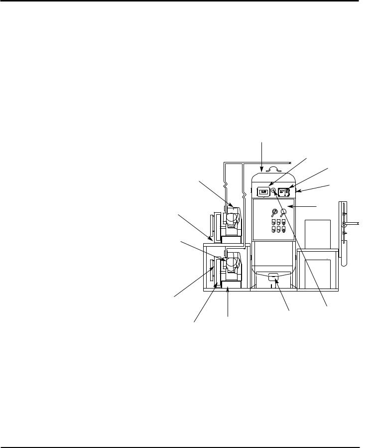
Compressor Parts List
|
Ref. |
|
|
|
|
|
No. Description |
Part Number |
Qty. |
||
1 |
Compressor Pump: |
|
|
|
|
|
|
5 HP |
OPT050 |
1 |
|
|
|
7-1/2 HP |
OPT100 |
1 |
|
|
|
10 HP |
OPT100 |
1 |
|
|
|
15 HP |
OPT150 |
1 |
|
|
2 |
Corrosion Resistant Vertical Tank |
|
|
|
|
|
120 Gal. |
Consult factory |
|
|
|
|
|
for number |
1 |
|
|
|
200 Gal. |
Consult factory |
|
|
|
|
|
for number |
1 |
|
|
|
240 Gal. |
Consult factory |
|
|
|
|
|
for number |
1 |
|
|
3 |
Dew Point Monitor/Probe |
|
|
|
|
|
Refrigerated |
ACO500100 |
1 |
|
|
|
Dessicant |
ACO500200 |
1 |
|
|
4 |
Carbon Monoxide |
|
|
|
|
|
Monitor/Sensor |
ACO600100 |
1 |
|
|
5 |
Safety Relief Valve |
Consult factory |
|
|
|
|
|
for number |
1 |
|
|
6 |
Control Panel |
Consult factory |
|
|
|
|
|
for parts and |
|
|
|
|
|
availability. Call |
|
|
|
|
|
1-888-769-7979. |
|
|
|
7 |
Pressure Gauge |
Consult factory |
|
|
|
|
|
for number |
1 |
|
|
8 |
Auto Tank Drain |
|
|
|
|
|
Electric |
ACO100100 |
1 |
|
|
|
Float |
ACO100200 |
1 |
|
|
9 |
Isolation Mounts |
Consult factory |
|
|
|
|
|
for parts and |
|
|
|
|
|
availability. Call |
|
|
|
|
|
1-888-769-7979. |
|
|
|
10 |
Drive Belts |
|
|
|
|
|
5 HP |
BT009900AV |
2 |
|
|
|
7-1/2 HP |
BT011200AV |
2 |
|
|
|
10 HP |
BT009200AV |
2 |
|
|
|
15 HP |
BT010200AV |
2 |
|
|
11 |
Pulley (Motor) |
|
|
|
|
|
5 HP |
PU009743AV |
1 |
|
|
|
7-1/2 HP |
PU009775AV |
1 |
|
|
|
10 HP |
PU009716AV |
1 |
|
|
|
15 HP |
PU009758AV |
1 |
|
|
12 |
Motor |
|
|
|
|
|
5 HP |
MC022307AV |
1 |
|
|
|
7-1/2 HP |
MC022370AV |
1 |
|
|
|
10 HP |
MC022372AV |
1 |
|
|
|
15 HP |
MC022376AV |
1 |
|
|
13 |
Belt Guard Back |
|
|
|
|
|
5 HP |
BG019502AJ |
1 |
|
|
|
7-1/2 HP |
BG218400AV |
1 |
|
|
|
10 HP |
BG218400AV |
1 |
|
|
|
15 HP |
BG218400AV |
1 |
|
|
|
Belt Guard Front |
|
|
|
|
|
7-1/2 HP |
BG218500AV |
1 |
|
|
|
10 HP |
BG218500AV |
1 |
|
|
|
15 HP |
BG218500AV |
1 |
|
|
2 |
|
3 |
|
4 |
1 |
5 |
|
|
13 |
6 |
|
|
12 |
|
11 |
7 |
|
|
|
8 |
10 |
9 |
|
6
Medical Package System
Dryer/Filter Parts List
Ref. |
|
|
|
No. Description |
Part Number |
|
|
1 |
Refrigerated Dryer: |
|
|
|
20 CFM |
ACO200020 |
|
|
25 CFM |
ACO200025 |
|
|
35 CFM |
ACO300035 |
|
|
45 CFM |
ACO000045 |
|
|
55 CFM |
ACO200055 |
2 |
|
60 CFM |
ACO200060 |
|
|
70 CFM |
ACO200070 |
|
|
100 CFM |
ACO200100 |
|
|
150 CFM |
ACO200150 |
|
|
200 CFM |
ACO200200 |
|
2 |
Filter Packages: |
|
1 |
|
1/2”-40 CFM |
MFP-040-342 |
|
|
|
||
|
1/2”-50 CFM |
MFP-050-342 |
|
|
3/4”-60 CFM |
MFP-060-362 |
|
|
1”-70 CFM |
MFP-070-382 |
|
|
1”-100 CFM |
MFP-110-382 |
|
|
1-1/4” -220 CFM |
MFP-220-3A2 |
|
See Filter System Manual for details and replacement elements.
Aftercooler/Drain
Ref. |
|
No. Description |
Part Number |
1 |
Aftercooler: |
|
|
5 HP |
ACO700015 |
|
7-1/2 -10 HP |
ACO700020 |
|
15 HP |
ACO700025 |
2 |
Drain Trap: |
|
|
5 - 15 HP |
Consult factory |
|
|
for number |
Left-End View
3 Piping Braided Flex: |
Consult factory for |
5 HP - 1/2 in. |
size and length. |
|
|
7-1/2 HP - 1/2 in. |
|
10 HP - 3/4 in. |
|
15 HP - 3/4 in. |
|
4Temperature Switches 400° N/O Switch
1
2
4
3
7

Oilless Oilless Reciprocating Air Compressor Pumps
Please read and save these instructions. Read carefully before attempting to assemble, install, operate or maintain the product described. Protect yourself and others by observing all safety information. Failure to comply with instructions could result in personal injury and/or property damage! Retain instructions for future reference.
Descriptions
GENERAL
Powerex utilizes cutting-edge compressor technology to provide the most advanced oilless reciprocating air compressor in the industry. The Powerex reciprocating compressor is available in single and two stage models. Continuously lubricated, sealed bearings provide oilfree compressed air and long compressor life. The onboard fan, finned flywheel and temperature reducing composite piston create lower operating temperatures.
DRY TYPE INLET FILTER
The inlet filter on the oilless compressor assures 99% of particulate free air, down to 10 micron, is admitted to the unit. Change every 2500 hours or more often in dirty locations (See Figure 5).
PISTON AND PISTON RINGS
The Powerex oilless reciprocating compressor pistons are made of a highstrength, self-lubricating composite using the most advanced technology available. These heat reducing pistons eliminate the effect of excessive grease leakage at the wrist pin bearing.
Teflon® rings reduce wear and provide self lubrication. Piston rings should be replaced every 10,000 hours of operation (See Figure 12).
BEARING REGREASE
The wrist pin bearings of the OPS and OPT oilless compressors are needle bearings protected by two outer lip seals. This needle bearing becomes impacted and requires regreasing at 5,000 hours (See Figure 15).
BEARING SEALS
The wrist pin bearing lip seals prevent the lubricating grease from leaking from the bearing area. The two lip seals on each connecting rod require replacement every 10,000 hours (See Figure 1622 or page 9).
Installation
INSTALLATION SITE
1.The oilless compressor must be located in a clean, well lit and well ventilated area.
2.The area should be free of excessive dust, toxic or flammable gases and moisture.
3.Never install the compressor where the ambient temperature is higher than 105o F or where humidity is high.
! DANGER
Breathable Air Warning
This compressor/pump is NOT equipped and should NOT be used “as is” to supply breathing quality air. For any application of air for human consumption, you must fit the compressor/pump with suitable in-line safety and alarm equipment. This additional equipment is necessary to properly filter and purify the air to meet minimal specifications for Grade D breathing as described in Compressed Gas Association Commodity Specification G 7.1 - 1966, OSHA 29 CFR 1910. 134, and/or Canadian Standards Associations (CSA).
DISCLAIMER OF WARRANTIES
In the event the compressor/pump is used for the purpose of breathing air application and proper in-line safety and alarm equipment is not simultaneously used, existing warranties are void, and Powerex disclaims any liability whatsoever for any loss, personal injury or damage.
Specifications
|
|
|
Max. |
SCFM @ |
|
No. of |
|
|
Flywheel |
|
|
Weight |
|
|
Model |
HP |
PSIG |
100 PSIG |
RPM |
Cyl. |
Bore |
Stroke |
O.D. |
Drive |
(lbs.) |
|
|
|
OPS 010 |
1 |
145 |
3.6 |
625 |
1 |
2.56 |
2.56 |
11.2 |
1 |
GR-A |
28 |
|
|
1.5 |
|
5.3 |
885 |
|
|
|
|
|
|
|
|
|
|
|
|
|
|
|
|
|
|
|
|
|||
|
|
|
|
|
|
|
|
|
|
|
|
|
|
|
OPS 030 |
2 |
145 |
6.6 |
845 |
2 |
2.56 |
2.36 |
13.8 |
1 |
GR-B |
53 |
|
|
3 |
10.1 |
1115 |
|
|||||||||
|
|
|
|
|
|
|
|
|
|
|
|||
|
OPT 050 |
5 |
145 |
17.2 |
860 |
2 |
4.31 x 2.95 |
3.35 |
16.9 |
2 |
GR-B |
110 |
|
|
|
|
|
|
|
|
|
|
|
|
|
|
|
|
OPT 100 |
7.5 |
145 |
27.5 |
855 |
3 |
3.54 x 2.95 |
3.35 |
18.3 |
2 |
GR-B |
165 |
|
|
10 |
35.0 |
1090 |
|
|||||||||
|
|
|
|
|
|
|
|
|
|
|
|||
|
OPT 150 |
15 |
145 |
47.0 |
1140 |
3 |
4.13 x 2.95 |
3.35 |
19.6 |
2 |
GR-B |
170 |
|
Powerex • 150 Production Drive • Harrison, OH 45030 • USA |
IN258603AV 9/04 |

Oilless Reciprocating Air Compressor Pumps
4.Clearance must allow for safe, effective inspection and maintenance.
Minimum Clearances
Above |
24” |
Drive belt side |
12” |
Other sides |
20” |
|
|
5.If necessary, use metal shims or leveling pads to level the compressor. Never use wood to shim the compressor.
VENTILATION
1.If the oilless compressor is located in a totally enclosed room, an exhaust fan with access to outside air must be installed.
2.Never restrict the cooling fan exhaust air.
3.Never locate the compressor where hot exhaust air from other heat generating units may be pulled into the unit.
WIRING
Refer to the general safety guidelines manual. All electrical hook-ups must be performed by a qualified electrician. Installations must be in accordance with local and national electrical codes.
Use solderless terminals to connect the electric power source.
PIPING
Refer to the general safety guidelines manual.
1.Make sure the piping is lined up without being strained or twisted when assembling the piping for the compressor.
2.Appropriate expansion loops or bends should be installed at the compressor to avoid stresses caused by changes in hot and cold conditions.
3.Piping supports should be anchored separately from the compressor to reduce noise and vibration.
4.Never use any piping smaller than the compressor connection.
5.Use flexible hose to connect the outlet of the compressor to the piping so that the vibration of the compressor does not transfer to the piping. Make
sure the flexible hose is rated for proper pressure and temperature before installing.
SAFETY VALVES
Tank mounted compressors are shipped from the factory with safety valves installed in the tank manifold. The flow capacity of the safety valve is equal to or greater than the capacity of the compressor.
1.The pressure setting of the safety valve must be no higher than the maximum working pressure of the tank.
2.Safety valves should be placed ahead of any possible blockage point in the system, i.e. shutoff valve.
3.Avoid connecting the safety valve with any tubing or piping.
4.Manually operate the safety valve every six months to avoid sticking or freezing.
HOURMETER
The hourmeter on the oilless compressor indicates the actual number of hours the unit has been in operation. The hourmeter is also used to determine maintenance and service timing.
An hourmeter must be installed with every oilless compressor.
CONDENSATE DRAIN VALVE
A condensate drain valve must be installed on any tank to allow removal of the liquid which will collect during compressor operation.
|
Drain liquid from |
|
NOTICE |
||
tank daily. |
Operation
Powerex oilless single stage compressors operate at a maximum pressure of 125 PSIG. Two stage compressors operate at a maximum of 145 PSIG and are equipped for continuous run operation. Compressor RPM’s are established by Powerex based on horsepower and operating pressure.
BEFORE START UP
1.Make sure all safety warnings, labels and instructions have been read and understood before continuing.
2.Remove any shipping materials, brackets, etc.
3.Confirm that the electric power source and ground have been firmly connected.
4.Be sure all pressure connections are tight.
5.Check to be certain all safety relief valves, etc., are correctly installed.
6.Check that all fuses, circuit breakers, etc., are the proper size.
7.Make sure the inlet filter is properly installed.
8.Confirm that the drain valve is closed.
9.Visually check the rotation of the compressor pump. If the rotation is incorrect, have a qualified electrician correct the motor wiring.
START-UP AND OPERATION
1.Follow all the procedures under “Before start-up” before attempting operation of the compressor.
2.Switch the electric source breaker on.
3.Open the tank discharge valve completely.
4.Check that the compressor operates without excessive vibration, unusual noises or leaks.
5.Close the discharge valve completely.
6.Check the discharge pressure. Also make sure the air pressure rises to the designated pressure setting by checking the discharge pressure gauge.
7.Check the operation of the pressure switch or the pilot valve for continuous run units by opening the stop valve and confirming the compressor starts or reloads as pressure drops.
Switch the breaker OFF if the compressor is not to be used for a long period of time.
|
These units are |
|
NOTICE |
||
equipped with |
head unloaders for continuous run operation.
2
 Loading...