

Page 1

Instruction Manual
Manual de Instrucciones
Manuel d’Instructions
S31SNGBC
ENGLISH ESPAÑOL
For Occasional Use Only
DANGER:
Read and follow all Safety Rules and Operating Instructions before
using this product. Failure to do so can result in serious injury.
PELIGRO:
Lea el manual de instrucciones y siga todas las advertencias e
instrucciones de seguridad. El no hacerlo puede resultar en lesiones graves.
DANGER:
Lirelemanueld’instructions etbienrespecter tous lesavertissements et toutes les instructions de sécurité. Tout défaut de le
faire pourrait entraîner des blessures graves.
Electrolux Home Products, Inc.
250 Bobby Jones Expressway
Augusta, GA 30907
CopyrightE2002 Electrolux Home Products, Inc.
530163728
FRANÇAIS
11/11/02
Page 2

UL CLASSIFIED PRODUCT NOTICE
Only the following Gasoline Powered Combination Gardening Appliance powerhead models
and their respective attachments have been Classified by Underwriters Laboratories, Inc., in
accordance with the applicable safety requirements.
Powerhead including brushcutter/trimmer attachment
Optional blower attachment
Thefollowingattachment isListedby Underwriter’sLaboratories,Inc.,in accordancewithUL Standard 1602, “Gasoline--Engine--Powered, Rigid--Cutting Member, Edgers and Edge--Trimmers.”
Optional edger attachment
S31SNGBC.............
SNB31......................................
SNE31.......................................
SAFETY RULES
WARNING:
appliances, basic safety precautions must always befollowed to reduce the risk of fire and
serious injury.
DANGER:
This unit can cause serious injury in-
gerous!
cluding amputation or blindness to the operator
and others. The warnings and safety instructions in this manual must be followed to provide
reasonable safety and efficiency in using the
unit.Theoperatorisresponsibleforfollowingthe
warningsandinstructionsinthismanualand on
the unit. Read the entire instruction manual before assembling and using the unit! Restrict the
use of this unit to persons who read, understand, and follow the warnings and instructions
in this manual and on the unit. Never allow children to operate this unit.
INSTRUCTION
MANUAL
DANGER:
away from material it does not cut. Blade
thrust can cause amputation of arms or legs.
Keep people and animals 50 feet (15 meters)
away.
When using gardening
This powertoolcan be dan-
SAFETY INFORMATION
ON THE UNIT
Blade can thrust violently
WARNING:
objects. Blade/trimmer line can throw objects
violently. Others can be blinded or injured.
Keep people and animals 50 feet (15 meters)
away.
WARNING:
as a fastening device for the blade.
WARNING:
spin after the throttle is released or, engine is
turnedoff.The coasting blade canthrowobjects
or seriouslycutifaccidentallytouched. Stop the
blade by contacting the right hand side of the
coasting blade with material already cut.
Stop coasting
blade by contact
with cut material.
Hazard zone for thrown
50 Feet
(15 Meters)
Donotusetrimmerhead
The blade continues to
Hazard Zone
WARNING:
throw objects violently. Y ouand others canbe
blinded or injured. Wear safety glasses and
leg protection.
ALWAYS WEAR:
Eye
Protection
Leg Guards
Boots
Blade/trimmer line can
Thrown
Objects
OPERATOR SAFETY
Dress properly. Always wear safety
S
glasses or similar eye protection when operating, or performing maintenance on your
unit (safety glasses are available). Eye
protection should be marked Z87.
Always wear face or dust mask if operation
S
is dusty.
2
Page 3

Alwayswearheavy,longpants,longsleeves,
S
boots,andgloves. Wearing safetylegguards
is recommended.
Always wear foot protection. Do not go
S
barefoot or wear sandals.
Secure hair above shoulder length. Secure
S
orr e m ov eloose clothingandjewelryorclothing with loosely hanging ties, straps, tassels,
etc. They can be caught in moving parts.
Being fully covered also helps protect you
S
from debris and pieces of toxic plants
thrown by spinning line/blade.
Stay Alert. Do not operate unit when you are
S
tired, ill, upset or under influence of alcohol,
drugs,ormedication. Watch whatyouare doing; use common sense.
Wear hearing protection.
S
Never start or run the engine inside a
S
closed room or building. Breathing exhaust
fumes can kill.
Keep handles free of oil and fuel.
S
Always use the handlebar and a properly
S
adjusted shoulder strap with a blade (see
ASSEMBLY).
UNIT/MAINTENANCE SAFETY
WARNING:
the spark plug before performing maintenance (except carburetor adjustments).
Look for and replace damaged or loose
S
parts before each use. Look for and repair
fuel leaks before use. Keep unit in good
working condition.
Throw away blades that are bent, warped,
S
cracked, broken, or damaged in any other
way. Replace trimmer head parts that are
cracked, chipped, broken, or damaged in
any other way before using the unit.
Maintain unit according to recommended
S
procedures. Keep blade sharp. Keep cutting line at the proper length.
Use only0.080!(2mm)diameter Snappert/
S
Weed Eater"brand replacement line.
Never use wire, rope, string, etc.
Install required shield properly before using
S
the unit. Use the metal shield for all metal
blade use. Use the plastic shield for all line
trimmer use.
Use only specified blade or trimmer head;
S
make sure it is properly installed and securely fastened.
Never start engine with clutch shroud re-
S
moved. The clutch can fly off and cause serious injury.
Besureblade ortrimmerheadstopsturning
S
when engine idles.
Make carburetor adjustments with the low-
S
er end supported to prevent blade or trimmer line from contacting any object. Hold
unit by hand; do not use the shoulder strap
for support.
Keep others away when making carburetor
S
adjustments.
Use only recommended Snappert/Weed
S
Eaterraccessories and replacement parts.
Have all maintenance and service not ex-
S
plained in this manual performed by your authorized service dealer .
Stop unit anddisconnect
FUEL SAFETY
Mix and pour fuel outdoors.
S
Keep away from sparks or flames.
S
Use a container approved for fuel.
S
Do not smoke orallow smoking near fuel or
S
the unit or while using the unit.
Avoid spilling fuel or oil. Wipe up all fuel
S
spills before starting engine.
Move at least 10 feet (3 meters) away from
S
fueling site before starting engine.
Stop engine and allow it to cool before re-
S
moving fuel cap.
Empty the fuel tank before storing or trans-
S
porting the unit. Use up fuel left in the carburetor by starting the engine and letting it
run until it stops.
Store unit and fuel in area where fuel vapors
S
cannot reach sparks or open flames from
water heaters, electric motors or switches,
furnaces, etc.
Always store gasoline in a container ap-
S
proved for flammable liquids.
CUTTING SAFETY
WARNING:
cut beforeeachuse. Remove objects (rocks,
broken glass, nails, wire, string, etc.) which
can be thrown or become entangled in the
blade or trimmer head.
Keep others including children, animals,
S
bystanders, andhelpers at least 50 feet (15
meters) away. Stop engine immediately if
you are approached.
Always keep engine on the right--hand side
S
of your body.
Hold the unit firmly with both hands.
S
Keep firm footing and balance. Do not over-
S
reach.
Keep blade or trimmer head below waist
S
level. Do not raise engine above your waist.
Keep all parts of your body away from
S
blade, trimmer head, and muffler when engine isrunning. A hotmufflercancauseserious burns.
Cut from your left to your right. Cutting on
S
right side of the shield will throw debris
away from the operator.
Use only in daylight or good artificial light.
S
Use only for jobs explained in this manual.
S
Inspect the area to be
TRANSPORTING AND STORAGE
Stop the unit before carrying.
S
Keep muffler away from your body.
S
Allow the engine to cool and secure the unit
S
before storing or transporting it in avehicle.
Empty the fuel tank before storing or trans-
S
porting the unit. Use upfuel leftinthecarburetor by starting the engine and letting it run
until it stops.
Store unit so the blade or line limiter blade
S
cannot accidentally cause injury. The unit
can be hung by the tube.
Store unit out of reach of children.
S
SAFETY NOTICE:
through prolonged use of gasoline powered
hand tools could cause blood vessel ornerve
damage in the fingers, hands, and joints of
people prone to circulation disorders or abnormal swellings. Prolonged use in cold
weather hasbeenlinked tobloodvesseldam-
Exposure to vibrations
3
Page 4
age inotherwise healthy people. If symptoms
occur such as numbness, pain, loss of
strength, change in skin color or texture, or
loss of feeling in the fingers, hands, or joints,
discontinue the useofthis tool and seekmedical attention. An anti --vibration system does
not guarantee the avoidance of these problems. Users who operate power tools on a
continual and regular basis must monitor
closely their physical condition and the condition of this tool.
SPECIAL NOTICE:
with a temperature limiting muffler and spark
arresting screen which meets the requirements of California Codes 4442 and 4443. All
This unit is equipped
ASSEMBLY
U.S. forest land and the states of California,
Idaho, Maine, Minnesota, New Jersey, Oregon, and Washington require by law that
many internal combustion engines be
equipped with aspark arresting screen. If you
operate inalocale wheresuchregulations exist, you arelegally responsible for maintaining
the operating condition of these parts. Failure
to do so is a violation of the law. For normal
homeowner use, the mufflerandsparkarresting screen will not require any service. After
50 hours of use, we recommend that your
muffler beserviced orreplaced by yourauthorized service dealer.
CARTON CONTENTS
Check carton contents against the following
list:
Powerhead
S
Brushcutter attachment
S
Blade shield screws (4)
S
Cupped washer
S
Large nut for installing blades
S
Hex wrench
S
Metal shield
S
Plastic shield
S
Shoulder strap with warning
S
4--point weed blade
S
Trimmer head (assembled on unit)
S
Handlebar (assembled on unit)
S
Wing nut (screwed onto shield)
S
Container of oil
S
WARNING:
connect spark plug before performing anyassembly procedures.
WARNING:
repeat all steps to ensure your unit is properly
assembled and all fasteners are secure.
Examine parts for damage. Do not use damaged parts.
NOTE:
missing or damaged, call 1-800-554-6723.
It is normal for the fuel filter to rattle in the
empty fuel tank.
Finding fuel or oil residue on muffler is normal
due to carburetor adjustments and testing
done by the manufacturer.
If you need assistance or find parts
Always stopunitanddis-
If received assembled,
TOOLS REQUIRED
Hex wrench (provided)
S
Adjustable wrench
S
INSTALLING BRUSHCUTTER
ATTACHMENT
CAUTION:
tachment, place the unit on a flat surface for
stability.
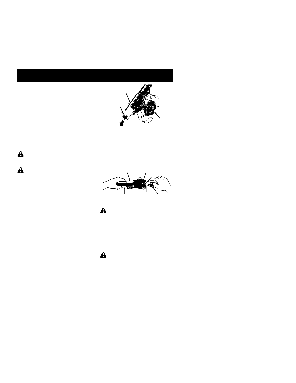
1. Loosen the coupler by turning the knob
counterclockwise.
When installing brushcutter at-
Coupler
Shipping
protector
TIGHTEN
2. Remove shipping protector from coupler.
3. Remove the tube cap from the brushcutter
attachment (if present).
4. Position locking/release button ofattachment into guide recess of coupler.
5. Pushtheattachment intothecoupleruntil
the locking/release button snaps into the
primary hole.
6. Before using the unit, tighten the knob securely by turning clockwise.
Coupler Primary Hole
Upper
Tube
WARNING:
release button is locked in the primary hole
and the knob is securely tightened before operating the unit. All attachments aredesigned
to be used in the primary hole.
For optional attachments, see the ASSEMBLY section of the applicable attachment instruction manual.
Locking/
Release
Button
Make sure the locking/
LOOSEN
Knob
Guide Recess
Lower
Attachment
ADJUST AND SECURE THE HANDLEBAR
DANGER:
barrier portion of the handlebar must be adjusted and remain installed as shown to provide a barrier between operator and the spinning blade. The handlebar clamp must be
positioned between the arrowsonthe handlebar decal.
Toavoid serious injury, the
4
Page 5
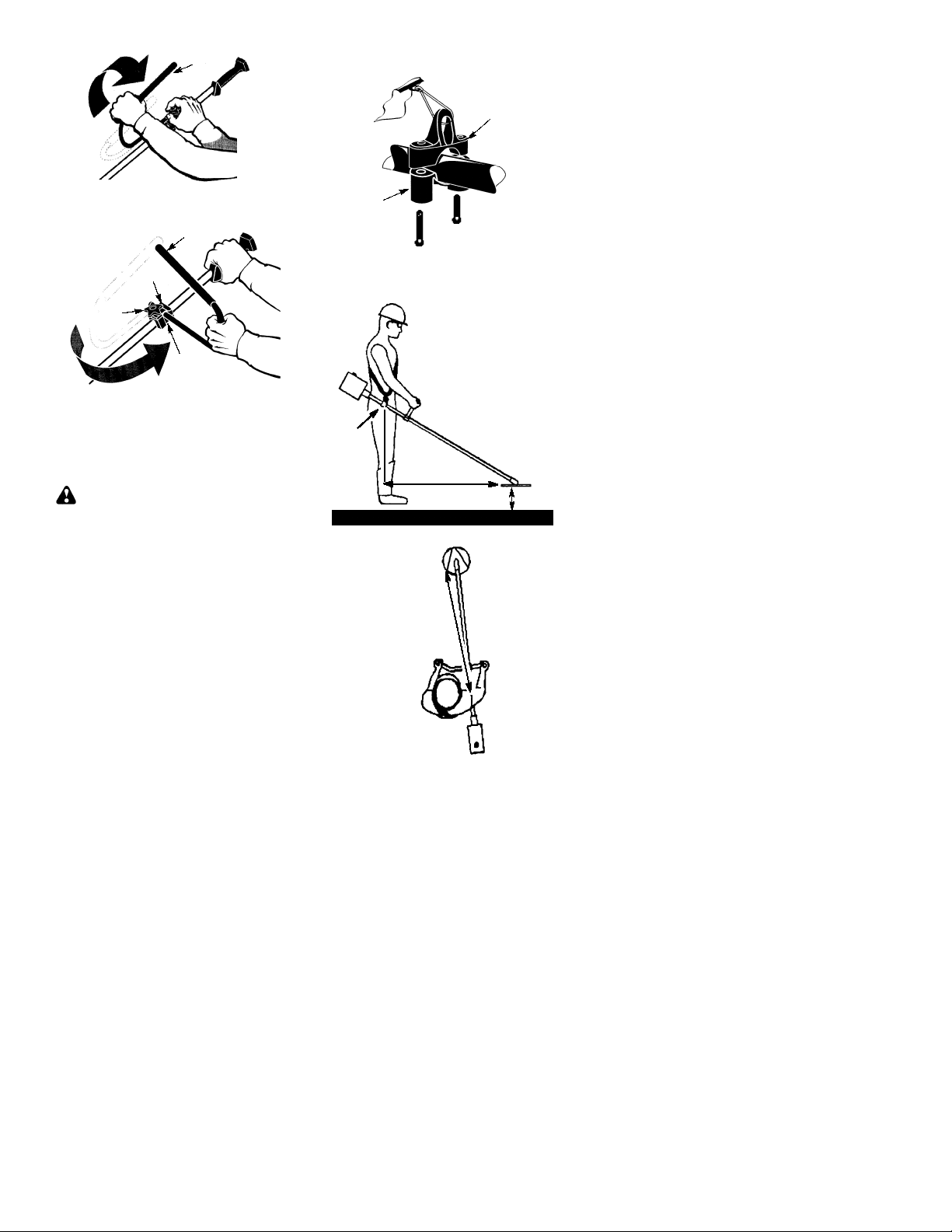
1. Lift handlebar to upright position.
Handlebar
2. Rotate handlebar/clamp counterclock-
wise toward engine until clamp falls into
groove of base.
Handlebar
3. Position the lower shoulder strap clamp
under the tube and align the upper and
lower clamp screw holes.
Upper Shoulder
Strap Clamp
Lower Shoulder
Strap Clamp
Screws
Handlebar
Clamp
Clamp
Knob
Clamp
Base
3. Place the handlebar in a comfortable
position.
4. Retighten handlebar by turning clamp
knob clockwise until handlebar is secure
and stationary in clamp base (clamp
knob can not be overtightened).
ASSEMBLY OF SHOULDER STRAP
WARNING:
and handlebar adjustments must be made with
the engine completely stopped before using
unit.
1. Insert your right arm and head through
the shoulder strap and allow it to rest on
your left shoulder. Make sure the danger
sign isonyour back and the hookisto the
right side of your waist.
A one-half twist is built in the shoulder
NOTE:
strap to allow the strap to rest flat on the shoulder.
2. Adjust the strap, allowing the hook to be
about 6 inches below the waist.
3. Fasten the strap hook to the clamp located
between the triggerhandleandthehandlebar clamp base and lift the tool to the operating position.
4. Try on shoulder strap and adjust for fit
and balance before starting the engine or
beginning a cutting operation.
NOTE:
shoulder strap clamp on the shaft for proper
balancing of unit.
TO RELOCATE SHOULDER STRAP
CLAMP:
1. Loosen and remove both clamp screws.
2. Place the upper shoulder strap clamp
It may be necessary to relocate the
over the tube.
Proper shoulder strap
4. Insert two screws into the screw holes.
5. Secure shoulder strap clamp by tightening screws with a hex wrench.
HARNESS
ADJUSTMENT
FOR BALANCE
6 inches
below
waist
30 inches
30 inches
4--12
inches
above
ground
CONFIGURING YOUR UNIT
Youcan configureyourunit using acuttinghead
for grass and light weeds, or a weed blade for
cuttinggrass,weeds, andbrushup to1/2inch in
diameter. Toassemble your unit, go to the section for the desired configuration and follow the
instructions.
5
Page 6
ASSEMBLY INFORMATION -TRIMMER HEAD
TRIMMER
HEAD
Removetheblade andmetalshield be-
NOTE:
fore attaching the plastic shield and trimmer
head. To remove blade, align hole in the dust
cup with the hole in the side of the gearbox by
rotating the blade. Insert a small screwdriver
into aligned holes. This willkeepthe shaftfrom
turning while loosening the blade nut. Remove
blade nut by turning clockwise. Remove the
screwdriver. Remove both washers and blade.
To removemetalshield,loosenandremovethe
four mounting screws. See ATTACHING THE
METAL SHIELD and INSTALLATION OF THE
METALBLADEforillustr a tion s . Besure tostore
all parts and instructions for future use.
ATTACHING THE PLASTIC SHIELD
AND TRIMMER HEAD
NOTE:
installed as shown in the illustration before
installing the trimmer head.
5. Align hole in the dust cup with the hole in
6. Insert a small screwdriver into aligned
7. While holding the screwdriver in position,
NOTE:
tioned with the raised section facing toward the
gearbox.
Make sure all parts are properly
the side of the gearbox by rotating the
dust cup.
holes. This will keep the shaft from turning while tightening trimmer head.
Screwdriver
thread trimmer head onto the shaft in the
direction shown on the decal (counterclockwise). Tighten until secure.
The retaining washer must be posi-
ASSEMBLY INFORMATION -- WEED
BLADE
WEED
BLADE
WARNING:
erly installed. The shield provides partial
protection to the operator andothers from the
risk of thrown objects, and is equipped with a
line limiter blade which cuts excesslinetothe
proper length. The line limiter blade (on underside of shield) is sharp and can cut you.
1. Remove wing nut from shield.
2. Insert bracket into slot on shield.
3. Pivot shield until bolt passes through hole
in bracket.
4. Tighten the wing nut securely.
NOTE:
the threads on thethreaded shaft, remove the
covering to expose the threads. Before
installing the trimmer head, make sure the
dust cup and retaining washer are positioned
on the gearbox as shown below.
If your unit has a plastic cover over
Bracket
Slot
Shield
Retaining Washer
The shield mustbeprop-
Wing Nut
Gearbox
Dust Cup
NOTE:
shield before attaching the metal shield and
installing the weed blade. T o remove the trimmerhead, alignholein thedust cupwiththe hole
in the side of the gearbox by rotating the dust
cup. Insert a small screwdriver into aligned
holes. This will keeptheshaft fromturningwhile
loosening the trimmer head. Remove the trimmer head by turning clockwise. Remove the
screwdriver. Toremovethe plastic shield, loosenandremove wing nut. Pivot shield to release
brac ket from slot. See INSTALLATION OF
THECUTTINGHEADand ATTACHINGTHE
PLASTIC SHIELD forillustrations. Be sureto
store all parts and instructions for future use.
Never use the trimmer head with the metal
blade installed.
Remove the trimmerheadandplastic
ATTACHING THE METAL SHIELD
WARNING:
be properly installed on the tool anytime the
tool is usedwitha blade. The forward tipofthe
metal shield helps to reduce the occurrence
of blade thrust which can cause seriousinjury
such as amputation to the operator or bystanders. Failure to install the shield in the
position shown can result in serious injury to
the operator. The length of the shield must be
aligned with the length of the tube.
The metal shield must
6
Page 7

1. Place the metal shield under the gearbox,
and align the screw holes.
Gearbox
Shield
6. Install the blade nut by threading onto the
shaft counterclockwise.
Gearbox
Shield
2. Insert and thread the 4 mounting screws
through the holes of the gearbox and the
metal shield. Tighten evenly andsecurely with the hex wrench provided.
INSTALLATION OF THE METAL
BLADE
WARNING:
when handling or performing maintenance on
the bladetoavoid injury. Thebladeissharpand
can cut you even when it is not moving.
WARNING:
fastening hardwareotherthanthe washersand
nuts shown in the following illustrations . These
parts must be provided by Poulan/Weed Eater
and installed as shown below. Failure to use
proper parts can cause the blade to fly off and
seriously hurt you or others.
NOTE:
located onthegearbox shaftandnot in theparts
bag. All other fastenersmentionedin the following assembly steps are in the parts bag.
1. Remove the retaining washer from the
2. Install the blade andthe retaining washer
3. Makesurethe raised part of the retaining
4. Slide the blade and retaining washer onto
5. Place the cupped washer onto the shaft.
Thedustcupand retaining washerare
threaded shaft of the gearbox. Leave the
dust cup on the shaft.
over the threaded shaft.
washer is facing the gearbox and the
raised area fits into the hole in the center
of the blade.
the shaft of the gearbox.
Make surethecupped side of thewasher
is toward the blade.
Wear protective gloves
Donotuseany blades, or
Dust Cup
Retaining
Washer
Cupped
Washer
NOTE:
lustrated, and the bladeissandwichedbetween
the dust cup and the retaining washer. There
should be no space between the blade and the
dust cup or the retaining washer.
7. Align hole in dust cup with hole in side of
8. Insert a small screwdriver into aligned
9. TIghtenbladenut firmlywitha wrenchwhile
10. Remove the screwdriver.
11. Turn blade by hand. If the blade binds
NOTE:
into aligned holes. Unthread the nut and remove parts. Be sure to store parts and instructions for future use.
Make sure all parts are in place as il-
gearbox by rotating the blade.
holes. This will keep the shaft from turn-
ing while tightening the blade nut.
Screwdriver
holding screwdriver in position.
againsttheshield, orappearsto beuneven,
the blade is not centered, and you mustreinstall.
To remove blade, insert screwdriver
Threaded Shaft
Blade
Nut
7
Page 8

OPERATION
KNOW YOUR UNIT
READ THIS INSTRUCTION MANUAL ANDSAFETY RULES BEFORE OPERATING YOUR UNIT .
Comparetheillustrationswithyou runit to familiarize yourselfwith the location of the variouscontrols
and adjustments. Save this manual for future reference.
Handlebar
Trimmer Head
Line Limiter
Blade
Blade
Tube
Shield
Throttle Trigger
Choke
Lever
Coupler
ON/OFF SWITCH
The ON/OFF switch is located on the trigger
handle andisusedto stop the engine. Movethe
switch to the OFF position to stop the engine.
PRIMER BULB
The PRIMER BULBremovesairfrom the carburetor and fuel lines and fills them with fuel.
This allows you to start the engine with fewer
pulls on the starter rope. Activate the primer
bulb by pressing it and allowing it to return to
its original form.
BEFORE STARTING ENGINE
WARNING:
information in the safety rules before you begin. If you do not understand the safety rules,
do not attempt to fuel your unit. Call
1-800-554-6723.
Be sure to read the fuel
FUELING ENGINE
WARNING:
when refueling.
This engine is certified to operate on unleaded
gasoline. Before operation, gasoline must be
mixed with a good quality synthetic 2-cycle aircooled engineoildesigned to bemixedat a ratio
of 40:1. Snappert/Weed Eaterrbrand synthetic oil is recommended. Mix gasoline and oil
at aratio of 40:1. A40:1r atiois obtained bymixing 3.2 ounces (95 ml) of oil with 1 gallon (4 liters) of unleaded gasoline.
DO NOT USE automotive oil or boat oil.
These oils will cause engine damage. When
mixing fuel, follow instructions printed oncontainer. Once oil is added to gasoline, shake
container momentarily to assure that the fuel
Remove fuel cap slowly
ON/OFF Switch
Starter Handle
Primer Bulb
Muffler
CHOKE
The CHOKE helps to supply fuel to the engine
to aid in cold starting. Activate the choke by
moving the choke lever to the FULL CHOKE
position. Afterthe engineattemptsto start, move
the choke lever to the HALF CHOKE position.
Once engine hasstarted,movethe choke lever
to the OFF CHOKE position.
COUPLER
The COUPLER enables optional attachments to be installed on the unit.
is thoroughly mixed. Always read and follow
the safety rules relating to fuel before fueling
your unit.
IMPORTANT
Experience indicates that alcohol blended
fuels (called gasohol or using ethanol or
methanol) can attract moisture which leads to
separation and formation of acids during storage. Acidic gas can damage the fuel system
of an engine while in storage.
Toavoid engine problems, empty the fuelsystem before storage for 30 days or longer.
Drain the gas tank, start the engine and let it
run until the fuel lines and carburetor are
empty. Use fresh fuel next season.
Never use engine or carburetor cleaner products in the fuel tank or permanent damage
may occur.
See the STORAGE section for additional information.
HOW TO STOP YOUR UNIT
To stop the engine, move the ON/OFF
S
switch to the OFF position.
If engine does not stop, move choke lever
S
to FULL CHOKE position.
8
Page 9

ON/OFF
Switch
Throttle Trigger
HOW TO START YOUR UNIT
WARNING:
turn while starting the engine. Avoid any contact with the muffler. A hot muffler can cause
serious burns.
The trimmer head will
STARTING A COLD ENGINE (or a
warm engine after running out of
fuel)
Starting Position
Starter Handle
Choke
Lever
Primer Bulb
Choke
position
decal
8. Pull starter rope sharply until engine runs,
but no more than 6 pulls. If the engine
doesn’t start after 6 pulls (at the HALF
CHOKE position), move the choke lever to
the FULL CHOKE position and press the
primer bulb 6 times. Squeeze and hold the
throttle trigger and pull the starter rope 2
more times. Move the choke lever to the
HALF CHOKE position and pull the starter
ropeuntiltheengineruns, but nomorethan
6 pulls. If the engine doesn’t start, repeat
procedure 2 additional times.
NOTE:
probablyflooded.ProceedtoSTARTINGA
FLOODED ENGINE.
9. Oncethe enginestarts,allowit to run10seconds, then move the choke lever to OFF
CHOKE by aligning lever with position
shownondecal (see illustrationbelow ). Allow the unit to run for 30 more seconds at
OFF CHOKE before releasing the throttle
trigger.
choke lever in the OFF CHOKE position,
movethechokelever to the HALFCH OKE
position and pull the rope until engine runs,
but no more than 6 pulls.
If engine still doesn’t start, it is
NOTE:
If engine dies with the
Muffler
1. Set unit on a flat surface.
2. MoveON/OFF switch to the ONposition.
3. Slowly press the primer bulb 6 times.
4. Move choke lever to FULL CHOKE by
aligning lever with position shown on decal (see illustration below).
Choke
position
decal
5. Squeeze the throttle trigger fully and hold
through
6. Pull starter rope handle sharply until en-
7. Assoonasengine sounds as if it istrying
all remaining steps.
gine sounds as ifitis trying to start, but do
not pull rope more than 6 times.
to start, move choke lever to HALF
CHOKE by aligning lever with position
shown on decal (see illustration below).
Choke
position
decal
STARTING A WARM ENGINE
1. MoveON/OFF switch to the ONposition.
2. Move the choke lever to the HALF
CHOKE position.
3. Squeeze and hold the throttle trigger.
Keep throttle trigger fully squeezed until
the engine runs smoothly.
4. Pull starter rope sharply until engine runs,
but no more than 5 pulls.
5. Allow engine to run 15 seconds, then
movethechokelevertothe OFFCHOKE
position.
If engine has not started, pull starter
NOTE:
rope 5more pulls. If engine still does not run,it
is probably flooded.
STARTING A FLOODED ENGINE
Flooded engines can be started by placing
the choke lever in the OFF CHOKE position;
then, pull the rope to clear the engine of excessfuel.Thiscould require pulling the starter
handle many times depending on how badly
the unit is flooded.
9
Page 10

If the unit still doesn’t start, refer to
TROUBLESHOOTING TABLE or call
1-800-554-6723.
OPERATING THE COUPLER
This model is equipped with a coupler which
enables optional attachments to be installed.
The optional attachments are:
Edger SNE31......................
Cultivator SNT31...................
Blower SNB31.....................
WARNING:
connect spark plug before removing or installing attachments.
Always stopunitanddis-
MODEL:
REMOVING TRIMMER ATTACHMENT (OR OTHER OPTIONAL
ATTACHMENTS)
CAUTION:
tachments, place the unit on a flat surface for
stability.
1. Loosen the coupler by turning the knob
counterclockwise.
Lower
Attachment
2. Press and hold the locking/release button.
Locking/Release
Button
Lower Attachment
3. While securely holding the engine and
upper tube, pull the attachment straight
out of the coupler.
When removing or installing at-
Upper Tube
Coupler
LOOSEN
TIGHTEN
Coupler
Knob
Upper Tube
INSTALLING OPTIONAL ATTACHMENTS
1. Remove the tube cap from the attachment (if present).
2. Position locking/release button ofattachment into guide recess of coupler.
3. Pushtheattachment intothecoupleruntil
the locking/release button snaps into the
primary hole.
4. Before using theunit, tighten the knob securely by turning clockwise.
Coupler
Upper
Tube
Primary Hole
Guide Recess
Locking/
Release
Button
Attachment
WARNING:
release button is locked in the primary hole
and the knob is securely tightened before operating the unit.
Make sure the locking/
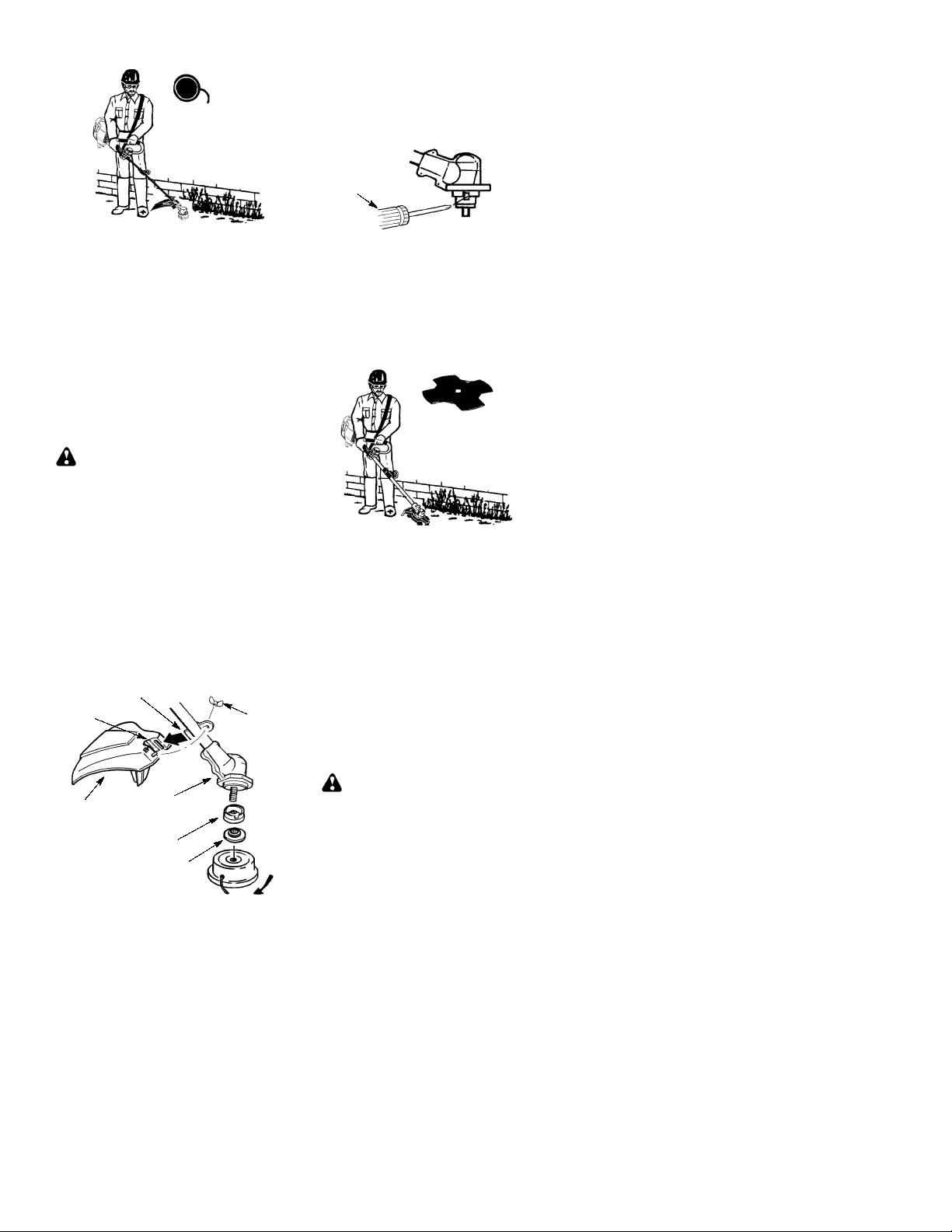
OPERATING POSITION
ALWAYS WEAR:
Hearing
Protection
Heavy,
Long Pants
Boots
Cut from your left to your right.
When operating unit, clip shoulder strap onto
clamp, stand as shown and check for the following:
Wear eye protection and heavy clothing.
S
Extend your left arm and hold handlebar
S
grip with your left hand.
Hold throttle grip with your right hand with
S
finger on throttle trigger.
Keep unit below waist level.
S
Keep shoulder strap pad centered on your
S
left shoulder and danger sign centered on
your back.
Maintain full weight of tool on your left
S
shoulder.
Without bending over, keep the blade or
S
trimmer head near and parallel to the
ground and not crowded into material being
cut.
Eye Protection
OPERATING INSTRUCTIONS FOR
USE WITH TRIMMER HEAD
WARNING:
tion. Never lean over the trimmer head. Rocks
or debris can ricochet or be thrown into eyes
and face and cause blindness or other serious
injury.
Before trimming, bring engine toaspeed sufficient to cut material to be trimmed.
Do not run the engine at a higher speed than
necessary. The cutting line will cut efficiently
when the engine is run at less than full throttle.
At lower speeds, thereis less engine noise and
vibration. The cutting line will last longer andwill
be less likely to “weld” onto the spool.
Always release the throttle trigger and allow
the engine to return to idle speed when not
cutting.
To stop engine:
Release the throttle trigger.
S
Move the ON/OFF switch to the OFF posi-
S
tion.
Always wear eye protec-
TRIMMER LINE ADVANCE
Thetrimmerline will advance approximately 2
in. (5 cm) each time the bottom of the trimmer
head is tapped on the ground with the engine
running at full throttle.
10
Page 11

The most efficient line length is the maximum
length allowed bytheline limiter. Alwayskeep
the shield in place whenthetool is being operated.
To advance line:
Operate the engine at full throttle.
S
Hold the trimmer headparallel toandabove
S
the grassy area.
Tap the bottom of the trimmer head lightly
S
onthegroundonetime. Approximately 2 in.
(5 cm) of line will be advanced with each
tap.
Always tap the trimmer head on a grassy
area. T apping on surfaces such as concrete
or asphalt can cause excessive wear to the
trimmer head.If the line is worn down to 2
inches (5 cm) or less, more than one tap will
be required to obtain the most efficient line
length.
Trimming
SCALPING
unwanted vegetation down to the ground. Hold
the bottom of the trimmer head about 3 in. (8
cm)above thegr oundand atanangle. Allowthe
tip of the line to strike the ground around trees,
posts, monuments, etc. This technique increases line wear .
-- The scalping technique removes
WARNING:
diameter line. Other sizes of line will not advance properly and can cause serious injury.
Do not use other materials such as wire,
string, rope, etc. Wire can break off during
cutting and become a dangerous missile that
can cause serious injury.
Use only 0.080!(2mm)
CUTTING METHODS
WARNING:
and donotcrowdthe line when cutting around
hard objects (rock, gravel, fence posts, etc.),
whichcandamage the trimmer head, become
entangled in the line, or be thrown causing a
serious hazard.
The tip of the line does the cutting. You will
S
achieve the best performance and minimum line wear by not crowding the line into
the cutting area. The right and wrong ways
are shown below.
The line will easily remove grass and
S
weedsfromaround walls,fences, trees and
flower beds, but it also can cut the tender
bark of trees or shrubs and scar fences.
For trimming or scalping, use less than full
S
throttle to increase line life and decrease
head wear, especially:
During light duty cutting.
S
Near objects around which the line can
S
wrap such as small posts, trees or fence
wire.
Formowingorsweeping, usefull throttle for
S
a good clean job.
TRIMMING
head about 3 inches (8 cm) above the ground
and atanangle. Allow only the tip ofthelineto
make contact. Do not force trimmer line into
work area.
-- Hold the bottom of the trimmer
Use minimum speed
MOWING
in places conventional lawn mowers cannot
reach. In the mowing position, keep the line
parallel to the ground. Avoid pressing the
head into the ground as this can scalp the
ground and damage the tool.
SWEEPING
line canbe used to blowaway loose debrisfrom
an area. Keep the line parallel to and above the
area surface and swing the tool from side to
side.
-- Y ourtrimmer is ideal for mowing
-- The fanningactionoftherotating
11
Page 12

OPERATING INSTRUCTIONS FOR
USE WITH WEED BLADE
Blade Thrust
S
when using a bladed unit. This reaction can
cause serious injury such as amputation.
Carefullystudythissection.Itis importantthat
you understand what causes blade thrust,
how you can reduce the chance of its
occurring, and howyoucanremainincontrol
of unit if blade thrust occurs.
WHAT CAUSES BLADE THRUST--Blade
S
Thrust
contacts an object that it does not cut. This
contact causesthe blade tostopfor aninstant
and then suddenly move or “thrust” away
from the object that was hit. The “thrusting”
reaction can be violent enough to cause the
operator to be propelled in any direction and
lose control of the unit. The uncontrolled unit
can cause seriousinjury if the blade contacts
the operator or others.
WHEN BLADE THRUST OCCURS
S
Blade Thrust
the blade snags, stalls, or binds. This is
more likely to occur in areas where it is
difficult to see the material being cut. By
using the unit properly, the occurrence of
blade thrust will be reduced and the
operator will be less likely to lose control.
is a reaction that only occurs
can occur when the spinning blade
can occur without warning if
Use the shoulder strap and keep a firm grip
S
on the unit with both hands. A properly
adjusted shoulder strap will support the
weight of the unit, freeing your arms and
handstocontrolandguidethe cutting motion.
Keep feet comfortably spread apart and
S
braced for a possible sudden, rapid thrust of
unit. Do not overreach. Keep firm footing and
balance.
Keep blade below waist level; it will be
S
easier to maintain control of unit.
Donotraisetheengineaboveyourwaist as
S
the blade can come dangerously close to
your body.
Do not swing unit with such force that you
S
are in danger of losing your balance.
Bring the engine to cutting speed before entering the material to be cut.If the blade does
not turn whenyou squeeze the throttle trigger,
make sure tube is fully inserted into the engine.
--
Always release the throttle trigger and allow
engine to return to idle speed when not cutting. The blade should not turn while the engine isrunning atidle. Ifthebladeturns atidle,
do not use your unit. Refer to theCARBURETOR ADJUSTMENT section or contact your
authorized service dealer.
Maintain good firm footing while using the
S
unit. Do this by planting feet firmly in a
comfortable apart position.
Cut while swinging the upper part of your
S
body from left to right.
Asyoumove forward tothe nextareato cut,
S
be sure to maintain your balance and
footing.
Cutonlygrass, weeds, andwoodybrushup
S
to 1/2 inch in diameter with the weed blade.
Do not let the blade contact material it
cannot cut such as stumps, rocks, fences,
metal, etc., orclusters ofhard, woodybrush
having a diameter greater than 1/2 inch.
Keep the blade sharp. A dull blade is more
S
likely to snag and thrust.
Cut only at full throttle. The blade will have
S
maximum cutting power and islesslikely to
bind or stall.
“Feed” the blade deliberately and not too
S
rapidly. The blade can thrust away if it isfed
too rapidly.
Cutonlyfrom yourlefttoyour right. Cuttingon
S
right side of the shield will throw debris away
from the operator .
ADDITIONAL SAFETY RULES
FOR OPTIONAL ATTACHMENTS
WARNING:
tachment used, read entire instruction manual before use and follow all warnings and instructions in manual and on attachment.
WARNING:
mains installed on upper tube (engine end of
unit) at all times.
For each optional at-
Ensure handlebar re-
RECOMMENDED CUTTING POSITION
Cut using the 2
o’clock to 4 o’clock
position of the
blade
WARNING:
mustnottry to clearawaycut material with the
engine running or the blade turning to avoid
serious injury. Stop engine and blade before
removing materials wrapped around blade or
tube.
The operator or others
Handlebar
2 o’clock
4 o’clock
12
Page 13

EDGER SAFETY
WARNING:
edged before each use. Remove objects
(rocks, broken glass, nails, wire, etc.) which
can be thrown by the blade or can wrap
around the shaft.
Blade rotates momentarily after the trigger
S
is released. The blade can seriously cut
you or others.
Allow blade to stop before removing it from
S
the cut.
Throw away blades that are bent, warped,
S
cracked, broken or damaged in any other
way. Replace parts that are cracked,
chipped, or damaged before using the unit.
Do not attempt to remove cut material nor
S
hold material to be cut when the engine is
running or when cutting blade is moving.
Always keep the wheel and depth adjusting
S
skid in contact with the ground.
Always push the unit slowly over the
S
ground. Stay alert for uneven sidewalks,
holes in the terrain, large roots, etc.
Always use the handlebar when using
S
edger attachment.
Inspect the area to be
BLOWER/VACUUM SAFETY
WARNING:
starting unit. Remove all debris and hard objects such as rocks, glass, wire,etc. that can
ricochet, be thrown, or otherwise cause injury
or damage during operation.
Donotset unit on anysurfaceexcept aclean,
S
hard area while engine is running. Debris
such as gravel, sand, dust, grass, etc., could
be picked up by the air intake and thrown out
through discharge opening, damaging unit,
property , or causing serious injury to
bystanders or operator.
Never place objects inside the blower
S
tubes, vacuum tubes or blower outlet.
Always direct the blowing debris awayfrom
people, animals, glass, and solid objects
such as trees, automobiles, walls, etc. The
forceof aircan causerocks, dirt,or sticksto
be thrown or to ricochet which can hurt
people or animals, break glass, or cause
other damage.
Never run unit without the proper
S
equipment attached. When using your unit
as a blower, always install blower tubes.
Check air intake opening, blower tubes or
S
vacuum tubes frequently, always with
engine stopped and spark plug
disconnected. Keep vents and discharge
tubes free of debris which can accumulate
and restrict proper air flow.
Inspect area before
Never place any object in air intake opening
S
asthiscouldrestrict properairflow andcause
damage to the unit.
Neveruse forspreading chemicals,fertilizers,
S
or other substances which may contain toxic
materials.
Toavoid spreadingfire, do notusenear leafor
S
brush fires, fireplaces, barbecue pits,
ashtrays, etc.
CULTIVATOR SAFETY
WARNING:
serious injury. Keep away from rotating tines.
Stop the engine and disconnect the spark plug
before unclogging tines or making repairs.
WARNING:
cultivated before starting the unit. Removeall
debris and hard and sharp objects such as
rocks, vines, branches, rope, string, etc.
Avoid heavy contact with solid objects that
S
might stop the tines. If heavy contact occurs,
stop the engine and inspect the unit for
damage.
Never operate the cultivator without the tine
S
cover in place and properly secured.
Keep the tines and guard clear of debris.
S
After striking a foreign object, stop the
S
engine, disconnect the spark plug and
inspect the cultivator for damage. Repair
before restarting.
Disconnect attachment from the drive engine
S
before cleaning the tines with a hose and
watertoremove anybuild--up. Oil the tines to
prevent rust.
Always wear gloves when servicing or
S
cleaning the tines. The tines become very
sharp from use.
Do not run unit at high speed unless
S
cultivating.
Rotating tines can cause
Inspect the area to be
HEDGE TRIMMER SAFETY
DANGER:
HANDS AWAY FROM BLADE -- Blade moves
momentarilyafterthe trigger isreleased. Donot
attempt to clear away cut material when the
bladeisinmotion. Make suretheswitch isinthe
OFF position, the spark plug wire is disconnected, and the blade has stopped moving before removing jammed material from the cutting
blade. Do notgrabor hold theunitby thecutting
blade.
Blades move
momentarily
after the
trigger is
released.
RISK OF CUT; KEEP
Allow blades to stop
before removing
them from the cut.
13
Page 14

WARNING:
starting the unit. Remove all debris and hard
objects such as rocks, glass, wire, etc. that
can ricochet, be thrown, or otherwise cause
injury or damage during operation.
Do not use a cutting blade that is bent,
S
warped, cracked, broken or damaged in
any other way. Have worn or damaged
parts replaced by an authorized service
dealer.
Always keep unit in front of your body.
S
Keep all parts of your body away from the
cutting blade.
Keep the cutting blade and airventsclearof
S
debris.
Inspect the area before
POLE PRUNER SAFETY
WARNING:
rotating chain can cause severe injury. Inspect the unit before use. Donotoperate unit
with abent,crackedordull blade ordullchain.
Keep away from the blade/chain.
WARNING:
rotating chain is sharp. Do not touch. Toprevent serious injury, always stop engine and
ensure blade/chain has stopped moving, disconnect spark plug, and wear gloves when
changing or handling the blade or chain.
WARNING:
ingchaincancauseinjurywhileit continues to
move after the engine is stopped. Maintain
proper control of the unit until the blade/chain
has completely stopped moving. Keep
hands, face and feet at a distance from all
moving parts. Do not attempt totouch orstop
the blade or chain when it is moving.
The reciprocating blade/
The reciprocating blade/
A coasting blade/rotat-
WARNING:
from power lines or electrical wires.
Only use for pruning limbs or branches up
S
to 4 inches in diameter.
Do not operate the unit faster than the
S
speed needed to prune. Do not run the unit
at high speed when not pruning.
Always stop the unit when work is delayed
S
orwhen walking from one cutting location to
another.
If you strike or become entangled with a
S
foreign object, stop the engine immediately
and check for damage. Have any damage
repaired by an authorized service dealer
before attempting further operations.
Discard blades that are bent, warped,
cracked or broken.
Stop the unit immediately if you feel
S
excessive vibration. Vibration is a sign of
trouble. Inspect thoroughly for loose nuts,
bolts ordamage before continuing. Contact
an authorized service dealer for repair or
replacement of affected parts as
necessary.
Keep the pruner away
SNOW THROWER SAFETY
WARNING:
away from the rotor when starting or running
the engine. Never attempt to clear the rotor
with the engine/motor running. Stop engine
and disconnect spark plug before unclogging
snow or debris from discharge chute or when
adjusting vanes.
Keep hands and feet
WARNING:
cause severe head injury. Wear head protection when operating this unit with a pole pruner attachment.
WARNING:
do not use more than one boom extension with
a pole pruner attachment.
Falling objects can
To prevent serious injury,
WARNING:
charge chute. Rocks or debris could be
thrown into the eyes and face and cause serious injury or blindness.
WARNING:
the unit is to be used. Remove objects that
could be thrown or damage the unit. Some
objects may be hidden by fallen snow -- be
alert for the possibility.
Direct material discharge away from glass
S
enclosures, automobiles, etc.
Do not run engine at high speed while not
S
removing snow.
Be attentive when using the snowthrower,
S
andstayalertforholes in theterrainand other
hidden hazards.
Make sure the rotor will spin freely before
S
attaching the snowthrower to the
powerhead.
If the rotorwillnotrotate freely due tofrozen
S
ice, thaw the unit before thoroughly before
attempting to operate under power.
Never lean over dis-
Inspect the area where
14
Page 15

Keep the rotor clear of debris.
S
Do not throw snow near other people. The
S
snow thrower could propel small objects at
high speed causing injury.
After striking a foreign object, stop the
S
engine, disconnect spark plug and inspect
the snowthrower for damage and repair if
necessary before restarting unit.
Never operate the snowthrower near glass
S
enclosures, automobiles and trucks.
Never attempt to use the snowthrower on a
S
roof.
Never operate the snowthrower near
S
window wells, dropoffs, etc.
MAINTENANCE
WARNING:
plug before performing maintenance except
for carburetor adjustments.
CHECK FOR LOOSE
FASTENERS AND PARTS
Spark Plug Boot
S
Air Filter
S
Housing Screws
S
Assist Handle Screw
S
Debris Shield
S
CHECK FOR DAMAGED OR
WORN PARTS
Contact an authorized service dealer for replacement of damaged or worn parts.
ON/OFF Switch -- Ensure ON/OFF switch
S
functions properly by moving the switch to
the OFF position. Make sure engine stops;
then restart engine and continue.
Fuel Tank -- Discontinue use of unit if fuel
S
tank shows signs of damage or leaks.
Debris Shield -- Discontinue use of unit if
S
debris shield is damaged.
INSPECT ANDCLEANUNIT ANDDECALS
After each use, inspect complete unit for
S
loose ordamaged parts. Clean the unit and
decals using a dampcloth with amilddetergent.
Wipe off unit with a clean dry cloth.
S
CLEAN AIR FILTER
A dirty air filter decreases engine performance and increases fuel consumption and
harmful emissions. Always clean after every
5 hours of operation.
Disconnect the spark
Never discharge snow onto public roads or
S
near moving traffic.
Clear snow from slopes by going up and
S
down; never across. Use caution when
changing directions. Never clear snow
from steep slopes.
Let snowthrower run for afewminutes after
S
clearing snow so moving parts do not
freeze.
Look behind and use care when backing
S
up. Exercise caution to avoid slipping or
falling, especially when operating in
reverse.
Know how to stop quickly.
S
1. Clean the cover and the area around it to
keep dirt from falling into the carburetor
chamber when the cover is removed.
2. Remove parts by pressing button to release air filter cover.
NOTE:
producing harmful evaporative emissions, do
not clean filter in gasoline or other flammable
solvent.
3. Wash the filter in soap and water.
4. Allow filter to dry.
5. Add a few drops of oil to the filter;
6. Replace parts.
To avoid creating a fire hazard or
squeeze the filter to distribute oil.
Button
Air Filter
Air Filter
Cover
REPLACE SPARK PLUG
Replace the spark plug each year to ensure
the engine starts easier and runs better. Set
spark plug gap at 0.025 in. Ignition timing is
fixed and nonadjustable.
1. Twist, then pull off spark plug boot.
2. Remove spark plug from cylinder and
discard.
3. Replace with Champion RCJ-6Y spark
plug and tighten securely with a 3/4 inch
socket wrench..
4. Reinstall the spark plug boot.
SERVICE AND ADJUSTMENTS
REPLACING THE LINE
1. Remove spool by firmly pulling on tap
button.
2. Clean entire surface of hub and spool.
3. Replacewith a pre-woundspool,or cut two
lengths of
ameterSnappert/WeedEaterrbrandline.
WARNING:
string, etc., which canbreak off andbecomea
dangerous missile.
feet of 0.080!(2 mm) di-
12-1/2
Never use wire, rope,
4. Insert ends of the lines about 1/2 inch (1
cm) into the small holes on the inside of
spool.
Spool
Small
Holes
15
Page 16

Line exit holes
Hub
5. Wind the line evenly and tightly onto the
spool. Wind in the direction of the arrows
found on the spool.
6. Push the lines into the notches, leaving 3
to 5 inches (7 -- 12 cm) unwound.
7. Insert the lines into the the exit holes in
the hub as shown in the illustration.
8. Align the notches with the line exit holes.
9. Push spool into hub until it snaps into
place.
10. Pull the lines extending outside of the hub
to release the lines from the notches.
Line in Notch
Line in Notch
BLADE REPLACEMENT
Refer to the ASSEMBLY section for blade replacement instructions and illustrations.
CARBURETOR ADJUSTMENT
The trimmer head, blade or optional
S
attachment moves/spins at idle.
Make adjustments with the unit supported so
the cutting attachment is off the ground and
will not make contact with any object. Hold
the unit byhandwhilerunningandmakingadjustments. Keep all parts of your body away
from the cutting attachment and muffler.
Idle Speed Adjustment
Allow engine to idle. Adjust speed until engine
runs without trimmer head, blade or optional
attachment moving or spinning (idle too fast)
or stalling (idle speed too slow).
Turn idle speed screw clockwise to
S
increase engine speed if engine stalls or
dies.
Turn idle speed screw counterclockwise to
S
decrease engine speed if trimmer head,
blade or optional attachment moves or
spins at idle.
WARNING:
after each adjustment. The trimmer head,
blade or optional attachment must not move
or spin at idle speed to avoid serious injury to
the operator or others.
Recheck the idle speed
WARNING:
making idle speed adjustments. The trimmer
head, blade or anyoptional attachment will be
spinning during most of this procedure. Wear
your protective equipment and observe all
safety precautions. After making adjustments, the trimmer head, blade or any optional attachment must not move/spin at idle
speed.
The carburetor has been carefully set at the
factory. Adjustments may benecessary ifyou
notice any of the following conditions:
Engine will not idle when the throttle is
S
released.
Keep others away when
STORAGE
WARNING:
steps after each use:
Allow engine to cool before storing or trans-
S
porting.
Store unit and fuel in a well ventilated area
S
where fuel vapors cannot reach sparks or
open flames from water heaters, electric
motors or switches, furnaces, etc.
Store unit with all guards in place. Position
S
unit so that any sharp object cannot accidentally cause injury.
Store unit and fuel well out of the reach of
S
children.
SEASONAL STORAGE
Prepare unit for storage at end of season or if
it will not be used for 30 days or more.
If your unit is to be stored for a period of time:
Clean the entire unit before lengthy
S
storage.
Store in a clean dry area.
S
Lightly oil external metal surfaces.
S
Perform the following
Air Filter
Cover
Idle Speed
Screw
If yourequire further assistance or areunsure
about performing this procedure, contact an
authorized service dealer or call
1--800--554--6723.
FUEL SYSTEM
Under FUELING ENGINE in the OPERATION section of this manual, seemessagelabeledIMPORTANT regarding the use of gasohol in your engine.
Fuel stabilizer is an acceptable alternative in
minimizing the formation of fuel gum deposits
during storage. Add stabilizer to the gasoline
in the fuel tank or fuel storage container. Follow the mix instructions found on stabilizer
container. Run engine at least 5 minutes after
adding stabilizer.
ENGINE
Remove spark plug and pour 1 teaspoon of
S
40:1, 2-cycleengine oil (air cooled) through
the spark plug opening. Slowly pull the
starter rope 8 to 10 times to distribute oil.
Replace spark plug with new one of recom-
S
mended type and heat range.
Clean air filter.
S
16
Page 17

Check entire unit for loose screws, nuts,
S
and bolts. Replace any damaged, broken,
or worn parts.
At the beginning of the next season, use
S
only fresh fuel having the propergasoline to
oil ratio.
OTHER
Do not store gasoline from one season to
S
another.
Replace your gasoline can if itstarts torust.
S
TROUBLESHOOTING TABLE
WARNING:
recommended remedies below except remedies that require operation of the unit.
Always stop unitanddisconnect spark plugbeforeperforming all ofthe
TROUBLE CAUSE REMEDY
Engine will not
start.
Engine will
not idle
properly.
Engine will not
accelerate,
lacks power,
or dies under
a load.
Engine
smokes
excessively.
Engine runs
hot.
1.ON/OFF switch in
OFF position.
2. Engine flooded.
3. Fuel tank empty.
4. Spark plug not firing.
5. Fuel not reaching
carburetor.
6. Carburetor requires
adjustment.
1. Carburetor requires
adjustment.
2. Crankshaft seals worn.
3. Compression low.
1. Air filter dirty.
2. Spark plug fouled.
3. Carburetor requires
adjustment.
4. Carbon build-up on
muffler outlet screen.
5. Compression low.
1. Choke partially on.
2. Fuel mixture incorrect.
3. Air filter dirty.
4. Carburetor requires
adjustment.
1. Fuel mixture incorrect.
2. Spark plug incorrect.
3. Carburetor requires
adjustment.
4. Carbon build-up on
muffler outlet screen.
1. Move ON/OFF switch to the ON
position.
2. See “Starting a Flooded Engine” in
Operation Section.
3. Fill tank with correct fuel mixture.
4. Install new spark plug.
5. Check for dirty fuel filter; replace.
Check for kinked or split fuel line;
repair or replace.
6. Contact an authorized service dealer.
1. See “Carburetor Adjustment” in
Service and Adjustments Section.
2. Contact an authorized service dealer.
3. Contact an authorized service dealer.
1. Clean or replace air filter.
2. Clean or replace plug
and regap.
3. Contact an authorized service dealer.
4. Contact an authorized service dealer.
5. Contact an authorized service dealer.
1. Adjust choke.
2. Empty fuel tank and refill with
correct fuel mixture.
3. Clean or replace air filter.
4. Contact an authorized service dealer.
1. See “Fueling Engine” in Operation
section.
2. Replace with correct spark plug.
3. Contact an authorized service dealer.
4. Contact an authorized service dealer.
17
Page 18

LIMITED WARRANTY
ELECTROLUX HOME PRODUCTS, INC.,
warrants to the original purchaser that each
Snapper
new
ment is free from defects in material and
workmanship and agrees to repair or replace
under this warranty any defective gasoline
product or attachment as follows from the
original date of purchase.
2 YEARS
household purposes.
90 DA YS
commercial, professional, or income producing purposes.
30 DAYS
purposes.
This warranty isnottransferable and does not
cover damage or liability caused by improper
handling, improper maintenance, or the use
of accessories and/or attachments not specifically recommended by
HOME PRODUCTS, INC.,
tionally, this warranty does not cover tuneups, spark plugs, filters, cutting line, or rotating head parts that will wear and require
replacement with reasonable use during the
warranty period. This warranty does not cov-
brand gasoline tool orattach-
tttt
-- Parts and Labor, when used for
-- Parts and Labor, when used for
-- Parts and Labor, if used for rental
ELECTROLUX
for this tool. Addi-
U.S. EPA
EMISSION CONTROL WARRANTY STATEMENT
YOUR WARRANTY RIGHTS AND OBLIGATIONS:
Agency and ELECTROLUX HOME PRODUCTS, INC., are pleased to explain the emissions control system warranty on your year
2002--2004 small off--road engine. ELECTROLUX HOME PRODUCTS, INC., must warrant
the emission control system on your small off-road engine for the periods of time listed below
provided there has been no abuse, neglect, or
improper maintenance of your small off--road
engine. Y our emission control system includes
parts such as the carburetor and the ignition
system. Where a warrantable condition exists,
ELECTROLUX HOME PRODUCTS, INC., will
repair your small off--road engine at no cost to
you. Expenses covered underwar rantyinclude
diagnosis, parts and labor.
ER’S WARRANTY COVERAGE:
sions related part on your engine (as listed under Emissions Control Warranty Parts List) is
defective or a defect in the materials or workmanshipoftheenginecauses the failureofsuch
anemissionrelatedpart,the partwillbe repaired
or replaced by ELECTROLUX HOME PRODUCTS, INC.
SPONSIBILITIES:
gine owner, you are responsible for the
performanceof the required maintenance listed
in your instruction manual. ELECTROLUX
HOME PRODUCTS, INC., recommends that
you retain all receipts covering maintenance on
your small off--road engine, but ELECTROLUX
HOME PRODUCTS, INC., cannot deny warranty solely for the lack of receipts or for your
The U. S. Environmental Protection
MANUFACTUR-
If any emis-
OWNER’S WARRANTY RE-
As the small off--road en-
er predelivery setup or normal adjustments
explained in the instruction manual.
THIS WARRANTY GIVES YOU SPECIFIC
LEGAL RIGHTS, AND YOU MAY HAVE
OTHER RIGHTS WHICH VARY FROM
STATE TO STATE.NO CLAIMS FOR CONSEQUENTIAL OR OTHERDAMAGES WILL
BE ALLOWED, AND THERE ARE NO
OTHER EXPRESS WARRANTIES EXCEPT THOSE EXPRESSLY STIPULATED
HEREIN.
SOME STATES DO NOT ALLOW LIMITATIONS ON HOW LONGANIMPLIED WARRANTY LASTS OR THE EXCLUSION OR
LIMITATIONS OF INCIDENTAL OR CONSEQUENTIAL DAMAGES, SO THE ABOVE
LIMITATIONS OR EXCLUSION MAY NOT
APPLY TO YOU.
The policy of
UCTS, INC.,
products. Therefore,
PRODUCTS, INC.,
change, modify, or discontinue models, designs, specifications, and accessories of all
products at any time without notice orobligation to any purchaser.
failure to ensure the performance of all scheduled maintenance. As the small off--road engine owner, you should be aware that ELECTROLUX HOME PRODUCTS, INC., may deny
you warranty coverage if your small off- -road
engine ora part ofithas failed due toabuse,neglect, impropermaintenance, unapproved modifications, or the use of parts not made or approved by the original equipment manufacturer .
You are responsible for presenting your small
off--road engine to a ELECTROLUX HOME
PRODUCTS, INC., authorized repair center as
soon as a problem exists. Warranty repairs
should be completed in areasonableamount of
time, not to exceed 30 days. If you have any
questionsregar dingyourwar r antyrights andresponsibilities, you should contact your nearest
authorized service center or call ELECTROLUX HOME PRODUCTS, INC., at
1--800--554--6723.
MENCEMENT DATE:
gins on the date the small off--road engine is
purchased.
warranty shall be for a period of two years from
the initial date of purchase.
ERED: REPAIR OR REPLAC EM ENT OF
PARTS.
rantedpartwill be performedat no charge to the
owner at an approved ELECTROLUX HOME
PRODUCTS, INC., servicing center. If you
have any questions regarding your warranty
rights and responsibilities, you should contact
your nearest authorized service center or call
ELECTROLUX HOME PRODUCTS, INC., at
1--800--554--6723.
ELECTROLUX HOME PROD-
is to continuously improve its
ELECTROLUX HOME
reserves the right to
WARRANTY COM-
The warrantyperiodbe-
LENGTH OF COVERAGE:
WHA T IS COV-
Repair or replacement of any war-
WARRANTY PERIOD:
18
This
Page 19

Any warranted part which is not scheduled for
replacementasrequired maintenance, orwhich
isscheduledonlyforregular inspectiontotheeffect of ”repair or replace as necessary” shall be
warrantedfor 2years. Anywarr antedpart which
is scheduled for replacement as required maintenance shallbewarrantedforthe periodoftime
up to the first scheduled replacement point for
that part.
charged for diagnostic labor which leads to the
determination that a warranted part is defective
if the diagnostic work is performed at an approved ELECTROLUX HOME PRODUCTS,
INC., servicing center.
DAMAGES:
UCTS,INC.,may be liablefordamages toother
engine components caused by the failure of a
warranted part still under warranty.
NOTC OVERED:
neglect, or improper maintenance are not covered.
useofadd--on ormodifiedparts can begrounds
for disallowing a warranty claim. ELECTROLUX HOME PRODUCTS, INC., is not liable to
cover failures of warranted parts caused by the
This engine is certified to be emissions compliant for the following use:
DIAGNOSIS:
ELECTROL UX HOME PROD-
ADD--ON OR MODIFIED PARTS:
Moderate (50 hours)
Intermediate (125 hours)
Extended (300 hours)
The owner shall not be
CONSEQUENTIAL
All failures caused by abuse,
WHA T IS
useofadd--onormodifiedparts.
ACLAIM:
your warranty rights and responsibilities, you
should contact your nearest authorized service
center or call ELECTROLUX HOME PRODUCTS, INC., at 1--800--554--6723.
GET WARRANTY SERVICE:
vices or repairs shall be provided at all ELECTROLUX HOME PRODUCTS, INC., service
centers. Call 1--800--554--6723.
NANCE, REPLACEMENT AND REPAIR OF
EMISSION RELATED PARTS:
TROLUX HOME PRODUCTS, INC., approved
replacement part used in the performance of
any warranty maintenance or repair on emission related parts will be provided without
chargetothe owner ifthe partisunder warranty.
EMISSION CONTROL WARRANTY PARTS
LIST:
(covered up to maintenance schedule), Ignition
The
Module.
owner is responsible for the performance of all
required maintenance as defined in the instruction manual.
If you have any questions regarding
Carburetor, Ignition System: Spark Plug
MAINTENANCE STATEMENT:
HOW TOFILE
WHERE TO
Warranty ser-
MAINTE-
Any ELEC-
The
19
 Loading...