

Page 1

Instruction Manual
Manual de Instrucciones
Manuel d’Instructions
For Occasional Use Only
ENGLISH
S1634 LE / S1838 LE
ESPAÑOL
WARNING:
Read and follow all Safety Rules and Operating Instructions before
using this product. Failure to do so can result in serious injury.
ADVERTENCIA:
Lea el manual de instrucciones y siga todas las advertencias e enstrucciones de seguridad. El no hacerlo puede resultar en lesiones
graves.
AVERTISSEMENT:
Lire le manuel d’instructions et bien respecter tous les avertissements et toutes les instructions de sécurité. Tout défaut de le faire
pourrait entraîner des blessures graves.
Electrolux Home Products, Inc.
250 Bobby Jones Expressway
Augusta, GA 30907
CopyrightE2003 ElectroluxHome Products, Inc.
530164161 6/26/03
FRANÇAIS
Page 2

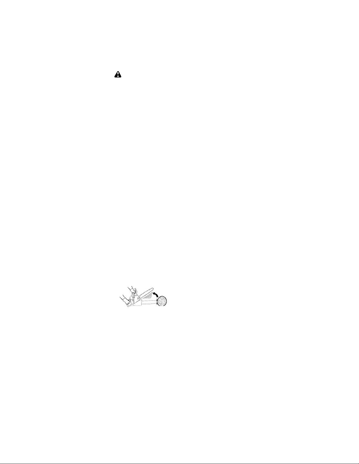
IDENTIFICATION OF SYMBOLS
WARNING!
saw can be dangerous! Careless orimproper usecancause
serio us or even fatal injury.
Alwayswearappropriateearprotection,eye protectionandheadprotection.
XX_
Measuredmaximum kickback value withoutchain brake for thebar
and chain combination on the label.
This chain
Always use two hands whenoperating the chain saw.
WARNING!
should be avoided; tip contact may cause the guide bar to
movesuddenlyupwardand backward,whichmay causeserious injury.
SAFETY RULES
WARNING:
spark plug wire andplace wire where it cannot contact spark plug to preventaccidental
starting when setting up, transporting, adjusting or making repairs except carburetor
adjustments.
Becauseachain saw is a high-speedwoodcutting tool, special safety precautions must
beobserved to reduce the risk of accidents.
Careless or improper use of this tool can
cause serious injury.
PLAN AHEAD
Read this manual carefully until you com-
S
pletely understand and can follow all safety
rules, precautions, and operating instructions before attempting to use the unit.
Restrict theuse ofyour saw to adultusers
S
who understand and can follow safety
rules, precautions, and operating instructions found in this manual.
Wear protective gear. Always use steel-
S
toed safety footwear with non-slip soles;
snug-fitting clothing; heavy-duty, non-slip
gloves; eye protection such as non-fogging, vented goggles or face screen; an
approvedsafety hardhat; andsoundbarriers (ear plugs or mufflers) to protect your
hearing. Regular users should have hearing checked regularly as chain saw noise
can damage hearing. Secure hair above
shoulder length.
Always disconnect
Read and understand the
instruction manual before
using the chain saw.
Contactingthe guide bar tip with any object
Hearing
Protection
Snug
Fitting
Clothing
Safety
Shoes
Keepall parts of your body away from the
S
chain when the engine is running.
Keepchildren, bystanders, and animals a
S
minimum of30feet(10meters)awayfrom
the work area. Do not allow other people
or animals to be near the chain saw when
starting or operating the chain saw.
Do not handle or operate a chain saw when
S
you are fatigued, ill, or upset, or if youhave
taken alcohol, drugs, or medication. You
must be in goodphysical condition and mentally alert. Chain saw work is strenuous. If
you have any condition that might be aggravated by strenuous work, check with your
doctor before operating a chain saw.
Safety Hat
Eye
Protection
Heavy Duty
Gloves
Safety Chaps
2
Page 3
Carefullyplanyour sawing operationinad-
S
vance. Do notstartcuttinguntil you havea
clearwork area,securefooting,and, if you
are felling trees, a planned retreat path.
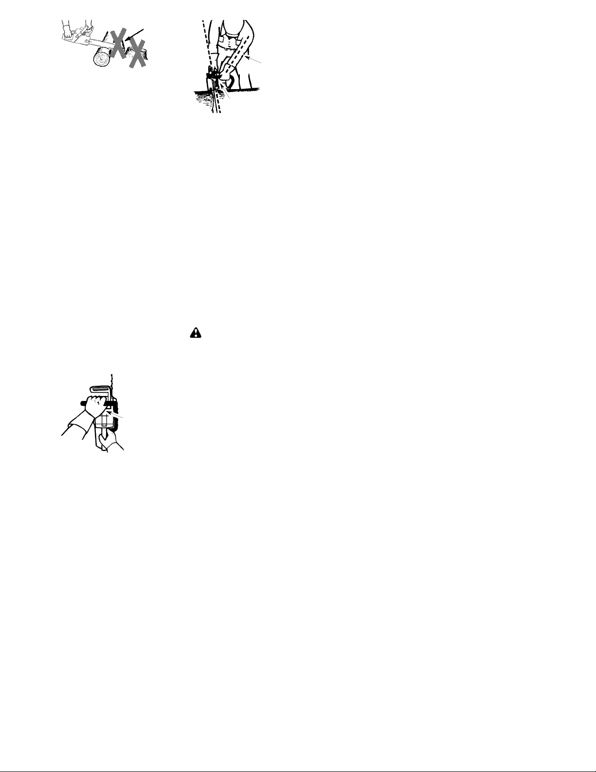
OPERATE YOUR SAWSAFELY
Donotoperateachain saw with one hand.
S
Serious injury to the operator,helpers, bystanders or any combination of these persons may result from one-handed operation. A chain saw is intended for
two-handed use.
Operatethe chain saw onlyin a well-venti-
S
lated outdoor area.
Do not operate saw from a ladder or in a
S
tree.
Makesurethechain will not make contact
S
with any object while starting the engine.
Never try to start the saw when the guide
bar is in a cut.
Do not put pressure on the saw at the end
S
of the cut. Applying pressure can cause
you to lose control when the cut is completed.
Stop the engine before setting the saw
S
down.
Do not operate a chain saw that is dam-
S
aged, improperly adjusted, or not completely and securely assembled. Always
replace bar, chain, hand guard, or chain
brakeimmediately if it becomes damaged,
broken or is otherwise removed.
With the engine stopped, hand carry the
S
chain saw with the muffler away from your
body, and the guide bar and chain to the
rear,preferably covered with a scabbard.
MAINTAIN YOUR SAW IN GOOD
WORKINGORDER
Haveall chain saw service performedbya
S
qualified service dealer with the exception
of theitems listed in the maintenancesectionofthis manual. For example, ifimpropertools are used to removeor hold the flywheelwhen servicing the clutch, structural
damage to the flywheel can occur and
cause the flywheel to burst.
Make certain the saw chain stops moving
S
when the throttle trigger is released. For
correction, refer to CARBURETOR ADJUSTMENTS.
Never modify your saw in any way.
S
Keepthe handles dry,clean, andfreeofoil
S
or fuel mixture.
Keep fuel and oil caps, screws, and fas-
S
teners securely tightened.
Use only Snappert/Poulan! acce ssories
S
and replacement parts as recommended.
HANDLE FUEL WITH CAUTION
Do not smoke while handling fuel or while
S
operating the saw.
Eliminate all sources of sparks or flame in
S
the areas where fuel is mixed or poured.
Thereshouldbe nosmoking,openflames,
orworkthat couldcausesparks. Allowengine to cool before refueling.
Mix and pour fuel in an outdoor area on
S
bare ground; store fuel in a cool, dry,well
ventilated place; and use an approved,
marked container for all fuel purposes.
Wipe up all fuel spills beforestartingsaw.
Move at least 10 feet (3meters) from fuel-
S
ing site before starting engine.
Turn the engine off and let saw cool in a
S
non-combustible area, not on dry leaves,
straw,paper ,etc. Slowly remove fuel cap
and refuel unit.
Storetheunit andfuel in anarea wherefuel
S
vapors cannot reach sparks or open
flamesfrom waterheaters,electric motors
or switches, furnaces, etc.
KICKBACK
WARNING:
can result in serious injury. Kickbackis the
backward,upwardorsuddenforwardmotion
of the guide bar occurring when the saw
chainnearthe uppertip of theguidebar contacts any object such as a log or branch, or
when the wood closes in and pinches the
sawchaininthecut. Contactingaforeignobject in the wood can also result in loss of
chain saw control.
RotationalKickbackcan occur when the
S
moving chain contacts an object at theupper tip of the guide bar. This contact can
cause the chain to dig into the object,
which stops the chain for an instant. The
result is a lightning fast, reverse reaction
which kicks the guide bar up and back toward the operator.
Pinch-Kickback can occur when the the
S
wood closes in and pinches the moving
saw chain in the cut along the top of the
guide bar and the saw chain is suddenly
stopped. This sudden stopping of the
chain results in a reversal of the chain
force used to cut wood and causes the
sawtomovein theoppositedirectionof the
chain rotation. The saw is driven straight
back toward the operator.
Pull-In can occur when the moving chain
S
contacts a foreign object in the wood in the
cut along the bottom of the guide bar andthe
sawchainis suddenly stoppe d. Thissudden
stopping pulls the saw forward and away
from the operator and couldeasily cause the
operator to lose control of the saw.
Avoid Pinch--Kickback:
Be extremely aware of situations or ob-
S
structions that can cause material topinch
the top of or otherwise stop the chain.
Do not cut more than one log at a time.
S
Do not twist the saw as the bar is with-
S
drawn from an undercut when bucking.
AvoidPull--In:
Always begin cuttingwith theengineatfull
S
speedandthesawhousing against wood.
Use wedges made of plastic or wood.
S
Never use metal to hold the cut open.
Avoid kickback which
Kickback Path
3
Page 4
Avoid Obstructions
Clear The Working Area
REDUCETHE CHANCE OF
KICKBACK
Recognize that kickback can happen.
S
With a basic understanding of kickback,
you can reduce the element of surprise
which contributes to accidents.
Neverletthemoving chain contact anyob-
S
ject at the tip of the guide bar.
Keep the working area free from obstruc-
S
tionssuchasothertrees,branches,rocks,
fences, stumps, etc. Eliminate or avoid
any obstructionthat your saw chain could
hit while you are cutting. When cutting a
branch, do not let the guide bar contact
branch or other objects around it.
Keep your saw chain sharp and properly
S
tensioned. A loose or dull chain can increase the chance of kickback occurring.
Follow manufacturer’s chain sharpening
andmaintenanceinstructions. Checktension at regular intervals with the engine
stopped, never with the engine running.
Make sure the chain brake nuts are securely tightenedafter tensioning thechain.
Begin andcontinue cutting at full speed. If
S
the chain is moving at a slower speed,
thereis greater chance of kickback occurring.
Cut one log at a time.
S
Use extreme caution when re-entering a
S
previous cut.
Do not attempt cuts starting with the tip of
S
the bar (plunge cuts).
Watch for shifting logs or other forces that
S
could close a cut and pinch or fall into
chain.
Use the Reduced--Kickback Guide Bar
S
and Low--Kickback Chain specified for
your saw.
MAINTAIN CONTROL
Stand to the
left of the saw
Thumb on
underside of
handlebar
Never reverse
hand positions
Elbow locked
Thumb on underside of
handlebar
Keepa good,firmgriponthesawwithboth
S
hands when the engine is running and
don’tletgo. Afirm gripwill helpyoureduce
kickback and maintain control of the saw.
Keep the fingers of your left hand encircling and your left thumb under the front
handlebar. Keep your right hand completely around the rear handle whether
yourarerighthandedorlefthanded. Keep
your left arm straight with the elbow
locked.
Position your left hand on the fronthandle-
S
bar so it is in a straight line with your right
hand on the rear handle when making
bucking cuts. Never reverseright and left
hand positions for any type of cutting.
Standwithyourweightevenly balancedon
S
both feet.
Stand slightly to the left side of the saw to
S
keep your body from being in a direct line
with the cutting chain.
Do not overreach. You could be drawn or
S
thrown off balance and lose control of the
saw.
Donot cut above shoulderheight. Itis diffi-
S
cult to maintain control of saw above
shoulder height.
KICKBACKSAFETY FEATURES
WARNING:
are included on your saw to help reducethe
hazard of kickback; however, such features
will not totally eliminate this danger. As a
chainsawuser,donotrelyonlyonsafety devices. You must follow all safety precautions, instructions, and maintenance in this
manual to help avoid kickback and other
forces which can result in serious injury.
Reduced--Kickback Guide Bar, designed
S
with a small radius tip which reduces the
size of the kickback danger zone on the
bar tip. A Reduced--Kickback Guide Bar
hasbeendemonstratedto significantly reducethenumberandseriousness of kickbacks when tested in accordance with
safety requirementsfor gasoline powered
chain saws as set by ANSI B175.1.
The following features
4
Page 5
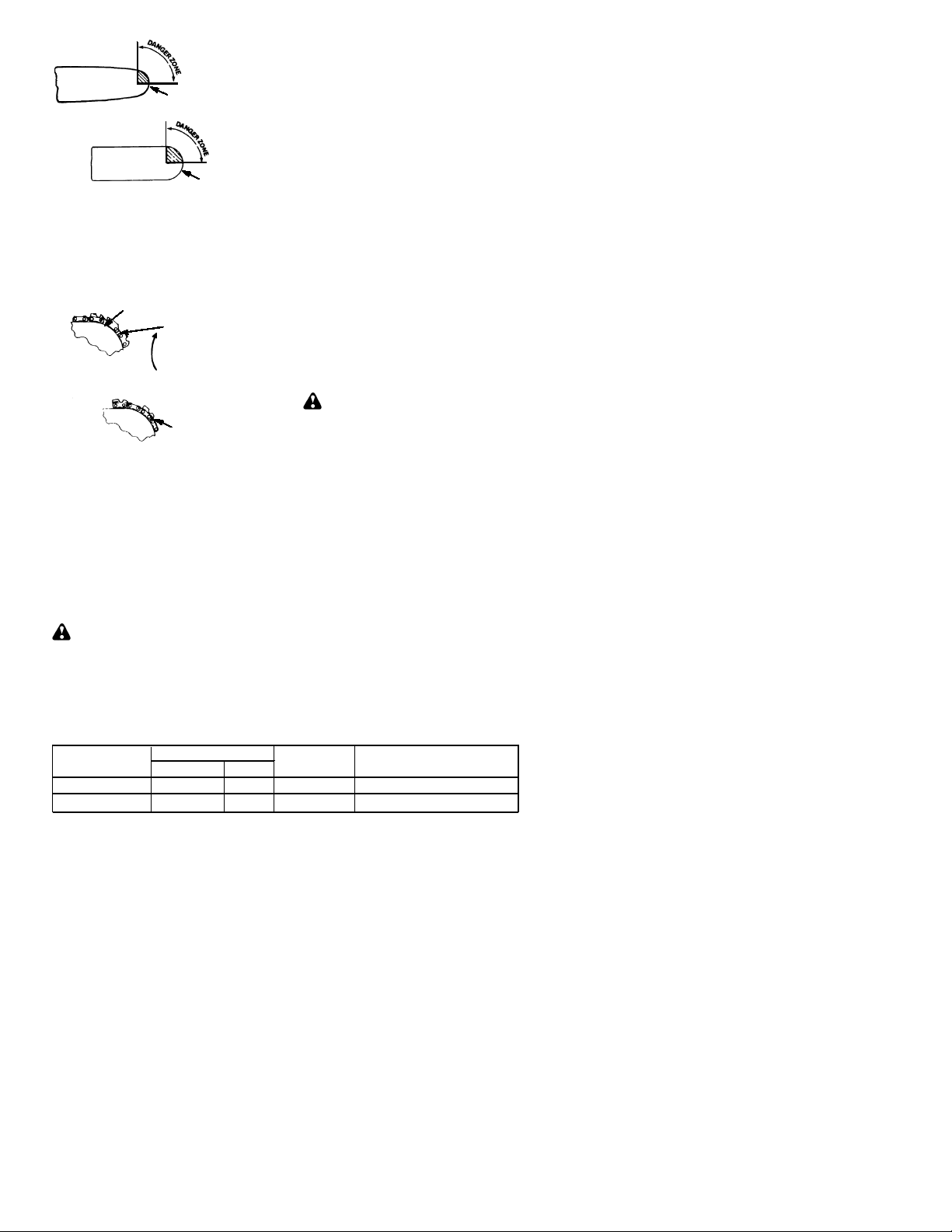
Reduced Kickback Symmetrical Guide Bar
Small Radius Tip
Symmetrical Guide Bar
Low--Kickback Chain, designed with a
S
contoured depth gauge and guard link
which deflect kickback force and allow
woodto gradually ride into thecutter.Low-Kickback Chain has met kickback performance requirements when tested on a
representative sample of chain saws below 3.8 cubic inch displacement specified
in ANSI B175.1.
Low---Kickback
Chain
Not a Low--- Kickback Chain
Front Hand Guard, designed to reduce the
S
chance of your lefthandcontacting thechain
if your hand slips off the front handlebar.
Position of front and rear handlebars, de-
S
signedwithdistancebetweenhandlesand
“in-line” with each other. The spread and
“in-line” position of the hands provided by
this design work together to give balance
and resistance in controlling the pivot of
the saw back toward the operator if kickback occurs.
CHAIN BRAKE AND CKA ANGLE
Chain Brake, designed to stopthechain in
S
the event of kickback.
WARNING:
RESENT AND YOU SHOULD NOT ASSUME THAT THE CHAIN BRAKE WILL
PROTECT YOU IN THE EVENT OF A KICKBACK. Kickback is a lightning fast action
which throws the bar and rotating chain back
and up toward the operator. Kickback can be
Contoured Depth Gauge
Large Rad ius Tip
Elongated Guard Link
Deflects
kickback force
and allows wood
to gradually ride
into cutter
Can Obstruct Material
WE DO NOT REP-
caused by allowing contact of the bar tip in the
danger zone with any hard object. Kickback
canalsobecausedbypinchingthesawchain
along the top of the guide bar. This action may
push the guide bar rapidly back toward theoperator. Either of these events may cause you
to lose contro lof the saw which could resultin
serious injury or even death. DO NOT RELY
UPON ANY OF THE DEVICES BUILT INTO
YOUR SAW. YOU SHOULD USE THE SAW
PROPERLY AND CAREFULL Y TO A VOID
KICKBACK. Reduced--kickback guide bars
and low--kickback saw chains reduce the
chance and magnitude of kickback and are
recommended. Your saw has a low kickback
chain and bar as original equipment. Repairs
on a chain brake should be made by an authorized servicing dealer. T ake your unit to the
place of purchase if purchased from a servicing dealer, or to the nearest authorized master
service dealer.
Tipcont act insomecasesmaycausealight-
S
ning fast reverse REACTION, kicking guide
bar up and back toward operator.
Pinching the saw chain along the top of the
S
guide bar may push the guide bar rapidly
back toward the operator .
Either of these reactions may cause you to
S
lose control of the saw which could result in
serious injury. Do not rely exclusively upon
devices builtinto your saw.
WARNING:
angle (CKA) listedonyoursaw andlisted inthe
CKA table below represents angle of kickback
your bar and chain combinations will have
when tested in accord ance with CSA (Canadian Standards Association) and ANSI standards. When purchasing replacement bar and
chain, considerations should be given to the
lower CKA values. Lower CKA values represent safer angles to the user, higher values indicate more angle and higher kick energies.
Computed ang les represented indicate total
energy and angle associated without activation
of the chain brake during kickback. Activated
anglerepresentschain stopping time relative to
activation angle of chain break and resulting
kick angle of saw. In all cases lower CKA values represent a safer operating environment
for the user.
The following guide bar and chain combinations meet kickback requirements of CSA
Standards Z62.1, Z62.3, & ANSI B175.1
when used on saws listed in this manual.
Use of bar and chain combinations other
than those listed is not recommended and
may not meet the CKA requirements per
standard.
Comp u t ed kickback
Computed kickback angle (CKA) Table
BAR
MODEL
S1634 LE
S1838 LE 952044418
P/N Length CHAIN P/N
952044370 16"
952051534
18" 952051535
5
CKA without chain brake
19
_
14
_
Page 6

NOTE:
r
mercial logging, a chain brake is required
and shall not be removed or otherwise disabledtocomply with Federal OSHA Regulations for Commercial Logging.
SAFETY NOTICE:
through prolonged use of gasoline powered
hand tools could cause blood vessel or nerve
damage in the fingers, hands, and joints of
people prone to circulation disorders or
abnormal swellings. Prolonged use in cold
weather has been linked to blood vessel
damage in otherwise healthy people. If
symptoms occur such as numbness, pain,
loss of strength,changein skincolor or texture,
or loss of feeling in the fingers, hands, orjoints,
discontinue the use of this tool and seek
medical attention. An anti-vibration system
does not guarantee the avoidance of these
problems. Users who operate power tools on
a continual and regular basis must monitor
closely their physical condition and the
condition of this tool.
SPECIALNOTICE:
with a temperaturelimiting muffler andspark
arresting screen which meets the
requirements of California Codes 4442 and
4443. All U.S. forest land and the states of
California, Idaho, Maine, Minnesota, New
Jersey, Oregon, and Washington require by
law that many internal combustion engines
tobeequippedwithaspark arrestingscreen.
Ifyou operateachainsaw inastate or locale
wheresuch regulationsexist, you are legally
responsible for maintaining the operating
condition of these parts. Failure to do so is
aviolation of the law. Refer to the SERVICE
section for maintenance of the spark
arresting screen.
Failuretofollowall SafetyRulesandPrecautionscanresult in serious injury. Ifsituations
occur which are not covered in this manual,
use care and good judgement. If you need
assistance, contact your authorized service
dealer or call 1-800--554--6723.
STANDARDS:
writer’s Laboratories, Inc., in accordance with:
ANSI B175.1--2000 American National
Standards for Gasoline--Powered Chain
Saws -- Safety Requirements
CSA Z62.1--1995 Chain Saws -- Occupational Health and Safety
CSA Z62.3--1996 Chain Saw Kickback Occupational Health and Safety
If this saw is to be used for com-
Exposure to vibrations
Y oursaw is equipped
Thissaw is listedby Under-
ASSEMBLY
Protective gloves (not provided) should be
wornduringassembly.
ATTACHINGTHEBAR& CHAIN
already attached)
WARNING:
repeat all steps to ensure your saw is properly
assem b led and all fasten ers are secure . Always wear gloves when handling the chain.
If received assembled,
(Ifnot
Thechain is sharp and can cut you even when
it is not moving!
1. Loosen and remove the chain brake
nuts and the chain brake from the saw.
2. Remove the plastic shipping spacer (if
present).
Chain Brake
3. An adjusting pin and screw is used to adjust the tension of the chain. It is very important when assembling the bar, that the
pin located on the adjusting screw aligns
into a hole in thebar. Turningthe screw will
move the adjustment pin up and down the
screw. Locate this adjustment before you
begin mounting the bar onto the saw. See
illustration below.
Adjustment located on Chain Brake
4. Turnthe adjusting screw by hand counterclockwise until the adjusting pin just
touches the stop. This should allow the
pin to be near the correct position.
5. Slide guide bar behind clutch drum until
guide bar stops against clutch drum
sprocket.
6. Carefully remove the chainfrom thepackage. Hold chain with the drive links as
shown.
Location of shipping space
Chain Brake
Nuts
Bar Tool
Inside view of
Chain Brake
Mount the Bar
CUTTERS MUST FACE IN
DIIRECTION OF ROTATION
Tip of
Bar
6
Page 7

Cutters
Drive Links
Depth Gauge
Checking the tension:
Use the screwdriver endof the chain adjustmenttool (bartool) to move the chain around
the bar. If the chain does not rotate, it is too
tight. If tooloose, thechainwill sagbelowthe
bar.
Place chain onto the sprocket
7. Place chain over and behind clutch, fitting the drive links in the clutch drum
sprocket.
8. Fit bottom of drive links between the
teeth in the sprocket in the nose of the
guide bar.
9. Fit chain drive links into bar groove.
10. Pull guidebarforwarduntilchain is snug
in guide bar groove. Ensure all drive
links are in the bar groove.
NOTE: CHAIN BRAKE MUST BE
DISENGAGED BEFORE INSTALLATIONON THESAW. TODISENGAGE
CHAIN BRAKE, PULL THE FRONT
HANDGUARD BACK TOWARDTHE
REAR OF THE CHAIN BRAKE AS
FARAS POSSIBLE(SEEILLUSTRATION).
DISENGAGED
Front Hand Guard
ENGAGED
Chain Brake
Chain Brake Nuts
Adjusting the tension:
Chain tension is very important. Chain
stretches during use. This is especially true
during the first few times you use your saw.
Always check chain tension each time you
use and refuel your saw.
Y oucan adjust the chain tension by loosening the chain brake nuts and turning the adjusting screw 1/4of a turnwhile lifting upon
the bar.
Ifchain is tootight, turnadjustingscrew1/4
S
turn counterclockwise.
If chain is too loose, turn adjusting screw
S
1/4 turn clockwise.
Chain Brake Nuts
Adjusting Screw -- 1/4 Turn
Lift up the tip of the bar and tighten the
S
chain brake nuts with the bar tool.
Recheck chain tension.
S
Chain Adjustment
Tool (Bar T ool)
Adjusting
Screw
Chain Brake
Nuts
Guide Bar
11. Now,install chainbrakemakingsurethe
adjusting pin is positioned in the lower
holeintheguide bar. Rememberthispin
moves thebar forwardand backward as
the screw is turned.
12. Install chain brake nuts and finger tighten only. Once the chain is tensioned,
youwill need to tightenchain brakenuts.
CHAIN TENSION
(Including units with chain already installed)
NOTE:
make sure the chain brake nuts are finger
tight only. Attempting to tension the chain
when the chain brake nuts are tight can
cause damage.
When adjusting chain tension,
WARNING:
with a loose chain, the chain could jump off
the guide bar and result in serious injury.
If the saw is operated
7
Page 8

OPERATION
KNOW YOUR CHAINSAW
READ THIS INSTRUCTION MANUAL AND SAFETY RULES BEFORE OPERATING YOUR
CHAINSAW. Comparetheillustrationswith your unit to familiarize yourself with the location of
the various controls and adjustments. Save this manual for future reference.
Chain
Adjustment Tool
(Bar Tool)
Chain
Front Hand Guard
Muffler
Front Handle
Starter Rope
ON/STOP
Switch
Primer
Bulb
Bar Oil Fill Cap
Cylinder Cover
Fast Idle
Lock
Throttle
Lockout
Rear
Handle
Throttle
Trigger
ON/STOP SWITCH
The ON/STOP SWITCH is used to stop the
engine.
THROTTLE TRIGGER
The THROTTLE TRIGGER controls engine
speed.
THROTTLE LOCK--OUT
The THROTTLE LOCK--OUT must be
pressed before you can squeeze the throttle
trigger. This feature prevents you from accidentally squeezing the trigger.
FAST IDLE LOCK
TheFAST IDLE LOCK holdsthe throttletrigger
in the starting position. Activate the fast idle
lock by pressing the throttle lockou t and
squeezing the throttle trigger. With the throttle
trigger squeezed, press the fast idle lock. Release the throttle lockout and triggerwhile holding the fast idle lock button .
CHOKE KNOB
The CHOKE KNOB activates the choke to
provide additional fuel to the engine during cold
starting.
Choke
Knob
Chain
Brake
Chain
Catcher
Adjusting
Screw
Starter
Housing
Chain Brake
Nuts
Fuel Mix Fill Cap
Guide Bar
Bar
Sprocket
Hole
PRIMER BULB
ThePRIMERBULB circulat es fuel to the carburetor to provide quickerstart ing.
CHAIN BRAKE
The CHAIN BRAK E is a dev ice designed to
stop the chain if kickback occurs. The chain
brake activates automatically in the event of
kickback. The chain brakeactivatesmanually
if the front hand guard is pushed forward. The
chainbrake is diseng aged by pulling thefront
hand guard back toward the front handle as far
as possible.
CHAIN TENSION
Itis normal for anewchain tostretch during first
15 minutes of operation. Y o u should check
your chain tension frequently. See CHAIN
TENSION under the ASSEMBLY section.
WARNING:
ingandafter use. Donot touch the muffler or
allow combustible material such as dry
grass or fuel to do so.
Muffler is very hotdur-
Chain
Direction
of Travel
8
Page 9

FUELING & LUBRICATION
STARTING
WARNING:
ly when refueling.
FUELING ENGINE
This engine is certified to operate on unleaded gasoline. Before operation, gasoline
must be mixed with a good quality synthetic
2-cycle air-cooled engine oil designed to be
mixedat aratioof40:1. SnappertorPoulan/
Weed Eaterrbrand synthetic oil is recommended. Mix gasoline and oil at a ratio of
40:1. A 40:1 ratio is obtained by mixing 3.2
ounces (95 ml) of oil with 1 gallon (4 liters) of
unleadedgasoline. Included with this sawis
a 3.2 ounce container of oil. Pour the entire
contentsofthiscontainerinto 1gallonof gasoline to achieve the proper fuel mixture.
DO NOT USE automotive oil or boat oil. These
oils will cause eng ine damage. When mixing
fuel, follow instructions printed on container.
Once oil is added to gasoline, shake container
momentarily toassure that the fuel is thoroughly mixed. Always read and follow the safety
rules relating to fuel before fueling your unit.
BAR AND CHAIN LUBRICATION
The bar and chain require continuous lubrication. Lubrication is provided by the automatic oiler system when the oil tank is kept
filled.Lack of oil will quickly ruin the bar and
chain. Too little oil will cause overheating
shownby smokecomingfromthechain and/
or discoloration of the bar.
Infreezingweather oil will thicken, making it
necessary to thin bar and chain oil with a
small amount (5to10%) of #1 Diesel Fuel or
kerosene. Bar and chain oil must be free
flowing for the oil system to pump enoughoil
for adequate lubrication.
GenuineSnappertbar and chainoil is recommended to protect your unit against excessive
wear from heat and friction. Snappertoil resists high temperature thinning.
IfSnappertbarandchain oil is not available,
use a good grade SAE 30 oil.
Neverusewasteoilforbarand chainlubri-
S
cation.
Always stop the engine before removing
S
the oil cap.
IMPORTANT
Experience indicates that alcohol--blended
fuels (called gasohol or using ethanol or
methanol) can attract moisture which leads
to separation and formation of acids during
storage. Acidic gas can damage the fuel
system of an engine while in storage. To
avoid engine problems, the fuel system
should be emptied before storage for 30
days or longer. Drain the gas tank, start the
engine and let it run until the fuel lines and
carburetor are empty. Use fresh fuel next
season. See STORAGE section for additional information.
Removefuel capslow-
WARNING:
move whenthe engine runs at idle speed. If
the chain moves at idle speed refer to CARBURETOR ADJUSTMENT within this
manual. Avoid contact with themuffler.A hot
muffler can cause serious burns.
To stop the engine move the ON/STOP
switch to the STOP position.
To start the enginehold the saw firmly on
the ground as illustrated. Make sure the
chain is free to turn without contacting any
object.
Use only 15”--18” of rope per pull.
Hold saw firmly while pulling starterrope.
Starter rope handle
Right foot through rear handle
IMPORTANTPOINTS TO REMEMBER
Whenpulling thestarterrope, do not use the
full extent of the rope as this can cause the
rope to break. Do not let starter rope snap
back. Hold the handle and let the rope rewind slowly.
Do not attempt to cut material with
NOTE:
thefastidlelockbuttoninthelockedposition.
The chain must not
Left hand
on front
handle
STARTING A COLD ENGINE (or
warm engine after running out of
fuel)
1. Move ON/STOP switch to the ON posi-
2. Pull choke knob out to the full extent.
3. Slowly press primer bulb 6 times.
4. Squeeze and hold throttle trigger. With
Throttle
lock--out
Throttle
trigger
5. Sharply pull the starter rope handle 5
ON/STOP SWITCH
(SIDE VIEW)
ON
STOP
tion.
thumbpress fast idlelock down;thenrelease throttle trigger.
Fast idle lock button
Choke knob
times with your right hand. Then, proceed to the next step.
9
Page 10

NOTE:
ing to start beforethe 5th pull, stop pulling
and immediately proceed to the next step.
6. Push the choke knob in completely (to
If the engine sounds as if it is try-
the OFF position); pull the starter rope
until the engine starts.
CHOKE
(SIDE VIEW)
back toward the front handle as far as
possible.
Whencuttingwiththe saw,the chainbrake
S
must be disengaged.
Disengaged
Engaged
Choke knob
7. Allow the engine to run forapproximately 5 seconds. Then, squeeze and release throttle trigger to allow engine to
return to idle speed.
OFF FULL
STARTING A WARMENGINE:
1. Move ON/STOP switch to the ON position.
2. Push the choke knob in completely (to
the OFF position).
3. Slowly press primer bulb 6 times.
4. Squeeze and hold throttle trigger. With
thumbpressfast idlelock down;thenrelease throttle trigger.
5. Sharply pull the starter rope with your
right hand until the engine starts.
6. Squeeze and release throttle trigger to
allow engine to return to idle speed.
DIFFICULT STARTING (or starting a
flooded engine):
The engine may be flooded with too much
fuel if it has not started after 10 pulls.
Flooded engines can be cleared of excess
fuel by following the warm engine starting
procedure listed above. Insure the ON/
STOPswitch is in the ON position.
Startingcouldrequirepullingthe starterrope
handle many times depending on how badly
theunitisflooded.If enginefailstostart,refer
to the TROUBLESHOOTINGTABLEor call
1-800-554-6723.
CHAIN BRAKE
WARNING:
worn too thin it may break when the chain
brakeis triggered.Witha brokenbrakeband,
the chain brake will not stop the chain. The
chainbrakeshouldbereplacedby anauthorizedservice dealer if any part is worntoless
than 0.020" (0.5 mm) thick. Repairs on a
chain brake should be made by an authorized service dealer. Take your unit to the
place of purchase if purchased from a servicing dealer, or to the nearest authorized
master service dealer.
This saw is equipped with a chain brake.
S
The brake is designed to stop the chain if
kickback occurs.
The inertia--activated chain brake is
S
activated if thefront hand guard is pushed
forward, either manually (by hand) or
automatically (by sudden movement).
If the brake is already activated, it is
S
disengagedby pulling thefronthandguard
If the brake band is
Braking function control
CAUTION:
checked several times daily. The engine
mustberunning whenperformingthis procedure. This is theonly instancewhenthesaw
should be placed on the ground with the engine running.
Place the saw on firm ground. Grip the rear
handlewith yourrighthandandthefronthandle with your left hand. Apply full throttleby
fully depressing the throttle trigger.Activate
the chain brake by turning your left wrist
against the hand guard without releasing
your grip around the front handle. The chain
should stop immediately.
The chain brake must be
Inertia activating function control
WARNING:
following procedure, the engine must be
turned off.
Grip therear handlewith your right hand and
thefronthandlewith your left hand. Holdthe
chainsawapproximately 14" (35cm) above
a stump or other wooden surface. Release
your grip on the front handle and use the
weight of the saw to let the top of the guide
bar fall forward and contact the stump.
When the tip of the bar hits the stump, the
brake should activate.
When performing the
CUTTING METHODS
IMPORTANT POINTS
Check chain tension before first use and
S
after 1 minute of operation. See CHAIN
TENSION in the ASSEMBLY section.
Cut wood only. Do not cut metal, plastics,
S
masonry, non-wood building materials, etc.
Stop the saw if the chain strikes a foreign
S
object. Inspect the saw and repair or replace parts as necessary.
Keep the chain out of dirt and sand. Even a
S
small amount of dirt will quickly dull a chain
andthusincreasethepossibilit yofkickback.
Practice cutting afew small logs using the
S
following techniques to get the “feel” of using your saw before you begin a major
sawing operation.
Squeeze the throttle trigger and allow
S
the engine to reach full speed before
cutting.
Begin cutting with the saw frame
S
against the log.
Keepthe engineat full speed the entire
S
time you are cutting.
10
Page 11

Allowthechaintocut foryou. Exert only
S
light downward pressure. If you force
thecut, damagetothebar,chain, orengine can result.
Release the throttle trigger as soonas
S
the cut is completed, allowing the engine to idle. If you run the saw at full
throttlewithouta cutting load,unnecessary wear can occur to the chain, bar,
and engine. It is recommended that
the engine not be operated for longer than 30 secondsat full throttle.
To avoidlosingcontrolwhencutiscom-
S
plete,donot putpressureonsaw at end
of cut.
Stop the engine before setting the saw
S
down after cutting.
TREE FELLING TECHNIQUES
WARNING:
dead branches which can fall while cutting
causingserious injury. Donotcutnearbuildingsorelectrical wires if you do not know the
directionoftreefall,norcut atnightsinceyou
will not be ale to see well, nor during bad
weathersuch as rain, snow, orstrongwinds,
etc. If thetreemakes contactwithanyutility
line, the utility company should be notified
immediately.
Carefullyplanyour sawing operationinad-
S
vance.
Clearthe workarea. Youneeda clear area
S
all aroundthe tree so you can have secure
footing.
The chain saw operator should keep on
S
the uphill side of the terrain as the tree is
likely torollorslidedownhill afteritisfelled.
Study the natural conditions that can cause
S
thetreetofallinaparticulardirection.
Natural conditions that can cause a tree to
fall in a particular direction include:
The wind direction and speed.
S
The lean of the tree. The lean of a tree
S
might not be apparent due to uneven or
sloping terrain. Usea plumb orlevel to de-
termine the direction of tree lean.
Weight and branches on one side.
S
Surrounding trees and obstacles.
S
Look for decay and rot. If thetrunk is rotted,
it can snap and fall toward the operator.
Check for broken or dead branches which
can fall on you while cutting.
Make sure thereis enoughroom for the tree
to fall. Maintain a distance of
lengthsfrom the nearest personor otherobjects. Enginenoisecandrownout a warning
call.
Remove dirt, stones, loose bark, nails, staples,andwirefromthe treewherecuts areto
be made.
Plana clearretreatpathto the rear anddiagonal to the line of fall.
Check for broken or
tree
2-1/2
Plan a clear retreat path
Direction of Fall
45
_
FELLING LARGE TREES
(6 inches in diameter or larger)
The notch method is used to fell large trees.
Anotchis cutonthe side ofthetreeinthedesired direction of fall. After a felling cut is
made on the opposite side of tree, the tree
will tend to fall into thenotch.
If the tree has large buttress
NOTE:
roots, remove them before making the
notch. If using saw to remove buttress
roots, keep saw chain from contacting
ground to prevent dulling of the chain.
NOTCH CUT AND FELLING THE
TREE
Make notch cut by cutting the top of the
S
notch first. Cut through
ofthetree. Nextcompletethenotch bycutting the bottom of the notch. See illustration. Once the notch is cut remove the
notch of wood from the tree.
Second cut
After removing the wood from the notch,
S
make the felling cut on the opposite side of
thenotch. This isdoneby makingacut about
two inches higher than the center of the
notch. This will leave enough uncut wood
bet w een thefellingcut andthe notchto form
a hinge. This hinge will help prevent thetree
from fallingin the wron gdirection.
Hinge holds tree on stump and helps
control fall
Final (felling) cut here. 2 inches above center of notch.
First cut
Notch
of the diameter
1/3
Hinge
Opening
of felling
cut
11
Closing of
notch
Page 12

NOTE:
wedges to open the cut if necessary to
controlthedirectionoffall. To avoid kickback
and chain damage, use wood or plastic
wedges, but never steel or iron wedges.
S
S
S
Beforefelling cut is complete, use
Be alert to signs that the tree is ready to
fall: cracking sounds, widening of the fell-
ing cut, or movement in the upper
branches.
As tree starts to fall, stop saw,put it down,
and get away quickly on your planned re-
treat path.
DO NOT cut down a partially fallen tree
withyour saw. Be extremely cautious with
partially fallen trees that may be poorly
supported. When a tree doesn’t fall com-
pletely,setthesawasideandpull downthe
tree with a cable winch, block and tackle,
or tractor.
CUTTINGA FALLENTREE
(BUCKING)
Bucking is the term used for cutting a fallen
tree to the desired log size.
WARNING:
being cut. Any portion can roll causing loss
of footing and control. Do not stand downhill
of the log being cut.
Donotstandon the log
IMPORTANT POINTS
Cut only one log at a time.
S
Cut shattered wood very carefully; sharp
S
pieces of wood could be flung towardopera-
tor.
Use a sawhorse to cut small logs. Never
S
allow another person to hold the log while
cuttingandnever hold thelogwith your leg
or foot.
Do not cut in an area where logs, limbs,
S
and roots are tangled such as in a blown
downarea. Dragthelogs into a clear area
beforecutting by pulling out exposedand
cleared logs first.
TYPES OF CUTTING USED FOR
BUCKING
WARNING:
pinched or hung in a log, don’t try to force it
out. Youcanlosecontrolofthesawresulting
in injury and/ordamage to the saw. Stop the
saw,drive awedgeofplastic orwoodinto the
cutuntil thesaw canberemoved easily. Restartthesawandcarefully reenterthecut. To
avoid kickback and chain damage, do not
usea metal wedge. Donot attempt torestart
your saw when it is pinched or hung in a log.
Use a wedge to remove pinchedsaw
If saw becomes
Overcutting
Undercutting
Undercuttinginvolves cuttingontheunderside ofthelog with top ofsaw againstthelog.
When undercutting use light upward pressure. Hold saw firmly and maintain control.
The saw will tendto push back toward you.
WARNING:
down to undercut. The saw cannot be controlled in this position.
Always make your first cut on the compression side ofthelog. Thecompression sideof
the log is where the pressure of the log’s
weight is concentrated.
First cut on compression side of log
Second cut
First cut on compression side of log
BUCKINGWITHOUTA SUPPORT
Overcut through
S
log.
Roll the log over and finish with a second
S
overcut.
Watch for logs with a compression side to
S
prevent the saw from pinching. See illustrations for cutting logs withacompression side.
Never turn saw upside
Second cut
of the diameter of the
1/3
BUCKINGUSING A LOG OR
SUPPORT STAND
Remember your first cut is always on the
S
compression side of the log.
(Refer to the illustrations below for your
first and second cut)
Y our first cut should extend
S
diameter of the log.
Finish with your second cut.
S
Using a log for support
nd
2
Cut
1/3
of the
Turn saw OFF and use a plastic or
wooden wedge to force cut open.
Overcutting begins on the top side of the log
with the bottom of the saw against the log.
When overcutting use light downward pressure.
1stCut
12
Page 13

2ndCut
Using a support stand
nd
Cut
2
st
1
Cut
1stCut
1stCut
Keepthetreebetweenyouandthechain.
S
Cut from the side of the tree opposite the
branch you arecutting.
Remove larger, supporting branches with
S
the cutting techniques described in BUCKING WITHOUT A SUPPORT.
Alwaysusean overcutto cutsmallandfree-
S
ly hanging limbs. Undercutting could cause
limbs to fall and pinch the saw.
PRUNING
WARNING:
shoulder height or below. Do not cut if
branches are higher than your shoulder. Get a
professional to do the job.
Makeyourfirst cut
S
bottom of the limb.
Next make a 2nd cut all the way through
S
thelimb. Then cutathird overcut leaving a
1 to 2 inch collar from the truck of the tree.
Limit pruning to limbs
ofthe way through the
1/3
nd
Cut
2
LIMBINGAND PRUNING
WARNING:
against kickback. Do not allow the moving
chain to contact any other branches or objects
at the nose of the guide bar when limbing or
pruning. Allowing such contact can result in
serious injury.
WARNING:
limb or prune. Do not stand on ladders, platforms, a log, or in any position which can cause
you to lose your balance or control of the saw.
IMPORTANT POINTS
Work slowly, keeping both hands firmly
S
gripped on the saw. Maintainsecurefoot ing
and balance.
Watch out for springpoles. Springpoles are
S
small size limbs which can catch the saw
chain and whip toward youor pull you off bal-
ance. Use extreme caution when cutting
small size limbs or slender material.
Be alert for springback. Watch out for
S
branches that are bent or underpressure.
Avoid being struck by the branch or the
saw when the tension in the woodfibers is
released.
Keep a clear work area. Frequently clear
S
branches out of the way to avoid tripping
over them.
LIMBING
Alwayslimbatreeafteritis cutdown. Only
S
thencan limbing be donesafely and prop-
erly.
Leave the larger limbs underneath the felled
S
tree to support the tree as you work.
Start at the base of the felled tree and work
S
toward the top, cutting branches and limbs.
Remove small limbs with one cut.
Be alert for and guard
Neverclimb intoa treeto
Third cut
Collar
Second cut
First cut
Pruning technique
SERVICE
WARNING:
plug beforeperforming maintenanceexcept
for carburetor adjustments.
We recommend all service and adjustments
not listed in this manual be performed by an
authorized or Master Service Dealer.
MAINTENANCE SCHEDULE
Check:
Fuel mixture level Before each use....
Bar lubrication Before each use.......
Chain tension Before each use.......
Chain sharpness Before each use....
For damaged parts Before each use..
For loose caps Before each use......
For loose fasteners Before each use...
For loose parts Before each use......
Inspect and Clean:
Bar Before each use................
Complete saw After each use.......
Air filter Every 5 hours*.............
Chain brake Every 5 hours*........
Spark arresting screen
and muffler Every 25 hours*.........
Replace spark plug
Replace fuel filter
* Hour s of Operation
13
Disconnect the spark
Yea r l y.
Yea r l y...
Page 14

AIR FILTER
CAUTION
or other flammable solvent to avoid creating
a fire hazard or producing harmful evaporative emissions.
Cleaning the air filter:
A dirty air filter decreases engine performance and increases fuel consumption and
harmful emissions. Always cleanafterevery
5 hours of operation.
1. Loosen 3 screws on cylinder cover.
2. Remove cylinder cover.
3. Remove air filter.
4. Cleanthe air filter usinghot soapywater.
5. Lightlyoil airfilter beforeinstalling to im-
6. Reinstall air filter.
7. Reinstall cylinder cover and 3 screws.
: Donot clean filter in gasoline
Rinse with clean cool water. Air dry
completely before reinstalling.
prove the efficiency of air filter. Use
2--cycle engine oil ormotoroil (SAE 30).
Squeeze excess oil from filter.
TIghten securely.
Air Filter
Cylinder Cover
Screws
Cylinder
Cover
INSPECT MUFFLER AND SPARK
ARRESTINGSCREEN
WARNING:
product contains chemicals known to the
State of California to cause cancer.
As the unit is used, carbondeposits build up
on the muffler and spark arresting screen,
andmust be removedto avoid creatinga fire
hazard or affecting engine performance.
Replacethesparkarresting screen if breaks
occur.
The muffler on this
CLEANING THE SPARK ARRESTING SCREEN
Cleaning is required every 25 hours of operation or annually, whichever comes first.
Outlet
Guide
Muffler
Backplate
1. Loosenandremovethelocknutfromthe
bolt cover.
Muffler
Gasket
Bolt Cover
Muffler
Bolts
Locknut
2. Remove the bolt cover.
3. Loosen and remove the 2 muffler bolts.
Removethemuffler,muffler gasket, outlet guide and backplate. Notice the orientationof thesepartsforreassembling.
4. Locate the 2 outlet cover screws on the
muffler. Loosen and remove both
screws.
5. Remove the outlet cover.
Outlet Cover
Screws
Spark Arresting
Screen
6. Remove spark arresting screen.
7. Clean the spark arresting screen with a
wire brush. Replace screen if any wires
arebrokenor screenis blocke daftercleaning.
8. Reinstall spark arresting screen.
9. Reinstall outlet cover and 2 screws. Ensure outlet cover and both screws are
reinstalledcorrectly (seeillustrations)to
prevent damage to the saw. The exhaust outlet must face the chain brake
(bar side) of the saw.
Exhaust
Outlet
Exhaust Outlet must face chain
brake (bar side) of chain saw
10. Inspect the muffler gasketandreplace if
damaged.
11. Reinstall backplate,outlet guide,muffler
gasket, and muffler using muffler bolts.
Tightenuntil secure.
12. Reinstall boltcover andlocknut. Tighten
securely.
BACK VIEW OF
MUFFLER
Muffler
Outlet Cover
CARBURETOR ADJUSTMENT
WARNING:
ing during most of this procedure.Wearyour
protective equipmentand observe all safety
precautions.Thechain mustnotmove atidle
speed.
The carburetor has beencarefully set at the
factory. Adjustments may be necessary if
you notice any of the following conditions:
Chain moves at idle. See IDLE SPEED--T
S
adjusting procedure.
Sawwill not idle. See IDLESPEED--T ad-
S
justing procedure.
Idle Speed--T
Allow engine to idle. If the chain moves, idle
istoofast. Iftheenginestalls, idle is too slow.
Adjust speed until engineruns withoutchain
movement (idle too fast) or stalling (idle too
slow). Theidle speed screw islocated in the
area above the primer bulb and is labeled T.
Thechainwill bemov-
14
Page 15

Turnidle speed screw (T) clockwise to in-
S
crease engine speed.
Turn idle speed screw (T) counterclock-
S
wise to decrease engine speed.
If you require further assistance or are unsure
about performing this procedure, contact your
authorized service dealer or call
1--800--554--6723.
BAR MAINTENANCE
Ifyour saw cuts to one side, has to be forced
throughthecut,orbeen runwithanimproper
amount of bar lubrication it may be necessarytoserviceyourbar. A wornbarwill damage your chain and make cutting difficult.
After each use, ensure ON/STOP switch is
in the STOPposition, thenclean all sawdust
from the guide bar and sprocket hole.
To maintain guide bar:
MoveON/STOPswitch to the STOP posi-
S
tion.
Loosen and removechain brake nuts and
S
chain brake. Remove bar and chain from
saw.
Clean the oil holes and bar groove after
S
each 5 hours of operation.
Remove SawdustFrom
Guide Bar Groove
Oil Holes
Burring of guide bar rails is a normal
S
process of rail wear. Remove these burrs
with a flat file.
Whenrailtopis uneven,usea flat file to re-
S
store square edges and sides.
Replace guide bar when the groove is worn,
theguidebar is bentor cracked, or whenexcess heating or burring of the rails occurs. If replacement is necessary, use only the guide bar
specified for your saw in the repair parts list or
onthedecallocatedonthechainsaw.
File Rail Edges
and Sides
Square
CorrectGrooveWorn Groove
CHAIN SHARPENING
Chain sharpening is a complicated task that
requires special tools. We recommended
you refer chain sharpeningto a professional
chain sharpener.
IGNITION TIMING
Ignition timing is fixed and nonadjustable.
SPARK PLUG
The spark plug should be replaced each
year to ensure the engine starts easier and
runs better.
1. Loosen 3 screws on cylinder cover.
2. Remove the cylinder cover.
3. Pull off the spark plug boot.
4. Remove spark plug from cylinder and
discard.
5. Replace with Champion RCJ--7Y spark
plugandtightensecurely with a3/4inch
socket wrench. Spark plug gap should
be 0.025 inches.
6. Reinstall the spark plug boot.
7. Reinstall the cylinder cover and 3
screws. Tightensecurely.
Screws
Spark
Plug Boot
Spark
Plug
Cylinder
Cover
STORAGE
WARNING:
to cool, and secure the unit beforestoring or
transporting in a vehicle. Store unit and fuel
in an area where fuel vapors cannot reach
sparks or open flames from water heaters,
electric motors or switches, furnaces, etc.
Storeunitwithall guardsin place. Position so
that any sharp object cannot accidentally
cause injury to passersby. Store the unit out
of reach of children.
Before storing, drain all fuel from the unit.
S
Start engine and allow to run until it stops.
Clean the unit before storing. Pay particu-
S
lar attention to the air intake area,keeping
it free of debris. Use a mild detergentand
sponge to clean the plastic surfaces.
Donotstorethe unit orfuel in a closed area
S
where fuel vapors can reach sparks or an
openflamefromhot waterheaters,electric
motors or switches, furnaces, etc.
Store in a dry area out of the reach of chil-
S
dren.
CAUTION
dep osits from forming in essential fuel system
parts such as the carburetor , fuel filter, fuel
hose, or fuel tank during storage. Alcohol
blended fuels (called gasohol or using ethanol
or methanol) can attract moisture which leads
to fuel mixture separation and formation of
acids during storage. Acidic gas can damage
the engine.
: It is important to prevent gum
Stopengine and allow
NEED ASSISTANCE?
NEED ASSISTANCE?
Call 1--800--554--6723.
NEED SERVICE PART?
Contact your dealer or place of purchase.
15
Page 16

TROUBLESH
O
O
WARNING:
therecommendedremediesbelow exceptremedies thatrequire operationof theunit.
TINGTABLE
Always stop unit and disconnect spark plug before performing all of
TROUBLE CAUSE REMEDY
Enginewill not
start or will run
only a few
seconds after
starting.
Enginewill
notidle
properly.
Enginewill not
accelerate,
lacks power,
or dies under
a load.
Engine
smokes
excessively.
Chain moves
at idle speed.
1. Ignition switch off.
2. Engine flooded.
3. Fuel tank empty.
4. Spark plug not firing.
5. Fuel not reaching
carburetor.
1. Idle speed requires
adjustment.
2. Carburetor requires
adjustment.
1. Air filter dirty.
2. Spark plug fouled.
3. Chain brake engaged.
4. Carburetor requires
adjustment.
1. Too much oil mixed with
gasoline.
1. Idle speed requires
adjustment.
2. Clutch requires repair.
1. Move ignition switch to ON.
2. See “Difficult Starting” in
Operation Section.
3. Fill tank with correct fuel mixture.
4. Install new spark plug.
5. Check for dirty fuel filter; replace.
Check for kinked or split fuel line;
repair or replace.
1. See “Carburetor Adjustment” in the
Service and Adjustments Section.
2. Contact an authorized service dealer.
1. Clean or replace air filter.
2. Clean or replace plug and regap.
3. Disengage chain brake.
4. Contact an authorized service dealer.
1. Empty fuel tank and refill with
correct fuel mixture.
1. See “Carburetor Adjustment” in the
Service and Adjustments Section.
2. Contact an authorized service dealer.
LIMITED WARRANTY
ELECTROLUX HOME PRODUCTS, INC.,
warrants to the original purchaser that each
new Snapper
free from defects in material and workmanship and agrees to repair or replace under
this warranty any defective gasoline chain
saw as follows from the original date of purchase.
1 YEAR -- Parts and Labor, when used for
Household purposes.
60 DAYS -- Parts and Labor, when used for
Commercial, Professional, or Income Producing purposes.
30DAYS-- Parts andLabor,if used forrental
purposes.
This warranty is not transferable and does
not cover damage or liability caused by improper handling, improper maintenance, or
the use of accessories and/or attachments
not specifically recommended by ELEC-
TROLUXHOMEPRODUCTS,INC.,for this
chain saw. Additionally, this warranty does
not cover damagecaused by improper handling, improper maintenance,or if the saw is
alteredin any waywhichinourjudgementaffectsits conditionoroperation.This warranty
does not cover tune--up, spark plugs, filters,
starterropes,startersprings,chainsharpening,bars,chains,andotherpartswhichwear
and require replacement with reasonable
useduringthewarrantyperiod.This warran-
brandgasoline chain saw is
tttt
ty does not cover predelivery set--up,installation of guide bar and chain, and normal adjustments explained in the instruction
manual such as carburetoradjustments and
chain tension adjustments. This warranty
does not cover transportation costs.
THIS WARRANTY GIVES YOU SPECIFIC
LEGAL RIGHTS, AND YOU MAY HAVE
OTHER RIGHTS WHICH VARY FROM
STATE TO STATE.
NO CLAIMS FOR CONSEQUENTIAL OR
OTHER DAMAGES WILL BE ALLOWED,
AND THERE ARE NO OTHER EXPRESS
WARRANTIES EXCEPT THOSE EXPRESSLYSTIPULATEDHEREIN.
SOME STATES DO NOT ALLOW LIMITATIONSON HOW LONGANIMPLIEDWARRANTY LASTS OR THE EXCLUSION OR
LIMITATIONS OF INCIDENTAL OR CONSEQUENTIAL DAMAGES, SO THE
ABOVE LIMITATIONS OR EXCLUSION
MAY NOT APPLYTO YOU.
The policy of ELECTROLUX HOME PRO-
DUCTS,INC.,is to continuously improveits
products.Therefore,ELECTROLUXHOME
PRODUCTS, INC., reserves the right to
change, modify, or discontinue models, designs, specifications, and accessories of all
productsatany time withoutnotice or obligation to any purchaser.
16
Page 17

U.S. EPA/CALIFORNIA/ENVIRONMENT CANADA
EMISSION CONTROL WARRANTY STATEMENT
YOURWARRANTYRIGHTS ANDOBLIGATIONS: The U.S. Environmental Protection
Agency,California Air Resources Board, Environment Canada and ELECTROLUX HOME
PRODUCTS, INC., are pleased to explain the
emissions control system warrant y on your
year 2002- -2004small off- -roadengine. In California, all new small off--road engines must be
designed, built, and equipped to meet the
State’s stringent anti--smog standards. ELECTROLUX HOME PRODUCTS, INC., must
warrant the emission control system on your
small off- -road engine for the periods of time
listed below provided there has been noabuse,
neglect, or impropermaintenanceof your small
off--road engine engine. Your emission control
system includes parts such as the carburetor
and the ignition system. Where a warrantable
condition exists, ELECTROLUX HOME
PRODUCTS, INC., will repair your small off-road engine engine at no cost to you. Expenses covered under warranty include diagnosis, parts and labor. MANUFACTURER’S
WARRANTY COVERAGE: If any emissions
related part on your engine (as listed under
Emissions Control Warranty Parts List) is defect iv eora defec tinthemate r ials orworkmanship of the engine causes the failure of such an
emission related part, the part will be repaired
or replaced by ELECTROLUX HOME PRODUCTS, INC. OWNER’S WARRANTY RE-
SPONSIBILITIES: Asthesmalloff--roadengine engine owner,you are responsible for the
performance of the required maintenance
listed in your instruction manual. ELECTROLUX HOME PRODUCTS, INC., recommends
that you retain all receipts covering main t enance on your small off- -road engine, but
ELECTROLUX HOME PRODUCTS, INC.,
cannot deny warranty solely for the lack of receipts or for your failure to ensure the performance of all scheduled maintenance. As the
small off--road engine engine owner, you
should be aware that ELECTROLUX HOME
PRODUCTS, INC., may deny you warranty
coverage if your small off- -road engine engine
or a part of it has failed due to abuse, neglect,
improper maintenance, unapproved modifications, or the use of parts notmade or approved
by the original equipment manufacturer. Y ou
are responsible for presenting your small off-road engine to an ELECTROLUX HOME
PRODUCTS, INC., authorized repair centeras
soon as a problem exists. Warranty repairs
should be completed in a reasonable amount
oftime, not to exceed30 days. If you have any
questions regarding your warranty rights and
resp onsibilities,you shouldcontact your nearest authorized service center or call ELECTROLUX HOME PRODUCTS, INC., at
1--800--554--6723. WARRANT Y COM-
MENCEMENT DATE: The warranty period
begins on the date the small off--road engine is
purchased. LENGTH OF COVERAGE: This
warranty shall be for a period oftwo years from
the initial date of purchase. WHAT IS COV-
ERED: REPAIR OR REPLACEMENT OF
PART S. Repair or replacement of any war-
ranted part will be performed at no charge to
the owner at an approved ELECTROLUX
HOME PRODUCTS, INC., servicing center.If
you have any questions regarding your warranty rights and respo nsibilities, you should
contact your nearest authorized servicecenter
or call ELECTROLUX HOME PRODUCTS ,
INC., at 1- -800--554--6723. WARRANTY PE-
RIOD: Any warranted part which is not scheduled for replacement as required maintenance,
or which is scheduled only for regular inspection to the effect of “repair or replace as necessary” shall be warranted for 2 years. Any warrantedpartwhich is scheduled forreplacement
asrequiredmaintenance shall be warrantedfor
theperiodoftimeuptothefirstscheduledreplacement point for that part. DIAGNOSIS:
The owner shall not be charged for diagnostic
labor which leads to the determination that a
warranted part is defective if the diagnostic
work is performed at an approved ELECTROLUX HOME PRODUCTS, INC., servicing
center. CONSEQUENTIAL DAMAGES:
ELECTROLUX HOME PRODUCTS, INC.,
may be liable for damages to other engine
components caused by the failure of a warranted part still under warranty.WHATIS NOT
COVERED: All failu r es caused by abuse, neglect, or improper maintenance are not covered. ADD--ON OR MODIFIED PARTS: The
use of add--on or modified parts can be
grounds for disallowing a warranty claim.
ELECTROLUX HOME PRODUCTS, INC., is
not liable to cover failures of warranted parts
caused by the use ofadd--onor modified parts.
HOW TO FILE A CLAIM: If you have any
questions regarding your warranty rights and
responsibilities,you shouldcont act your nearest authorized service center or call ELECTROLUX HOME PRODUCTS, INC., at
1- -800--554--6723. WHERE TO GET WAR-
RANTY SERVICE: Warranty services or repairs shall be provided at all ELECTROLUX
HOME PRODUCTS, INC., service centers.
Call: 1- -800- -554--6723 MAINTENANCE, RE-
PLACEMENT AND REP AIR OF EMISSION
RELA TED PARTS: Any ELECTROLUX
HOME PRODUCTS, INC., approvedreplacement part used in the performance of any warranty maintenance or repair on emission related parts will be provided without charge to
the owner if the part is under warranty. EMIS-
SIONCONTROLWARRANTY PARTSLIST:
Carburetor, Ignition System: Spark Plug (covered up to maintenance schedule), Ignition
Module, Muffler including catalyst. MAINTE-
NANCE STA TEMENT: Theownerisresponsible for the performance of all required maintenance as defined in the instruction manual.
17
Page 18

The information on the product label indicates which standard your engine is certified.
Example: (Year)EPAPhase 1 or Phase 2 and/or CALIFORNIA.
This engine is certified to be emissions compliant for the following use:
Moderate (50 hours)
Intermediate (125 hours)
Extended (300 hours)
18
 Loading...