

Page 1
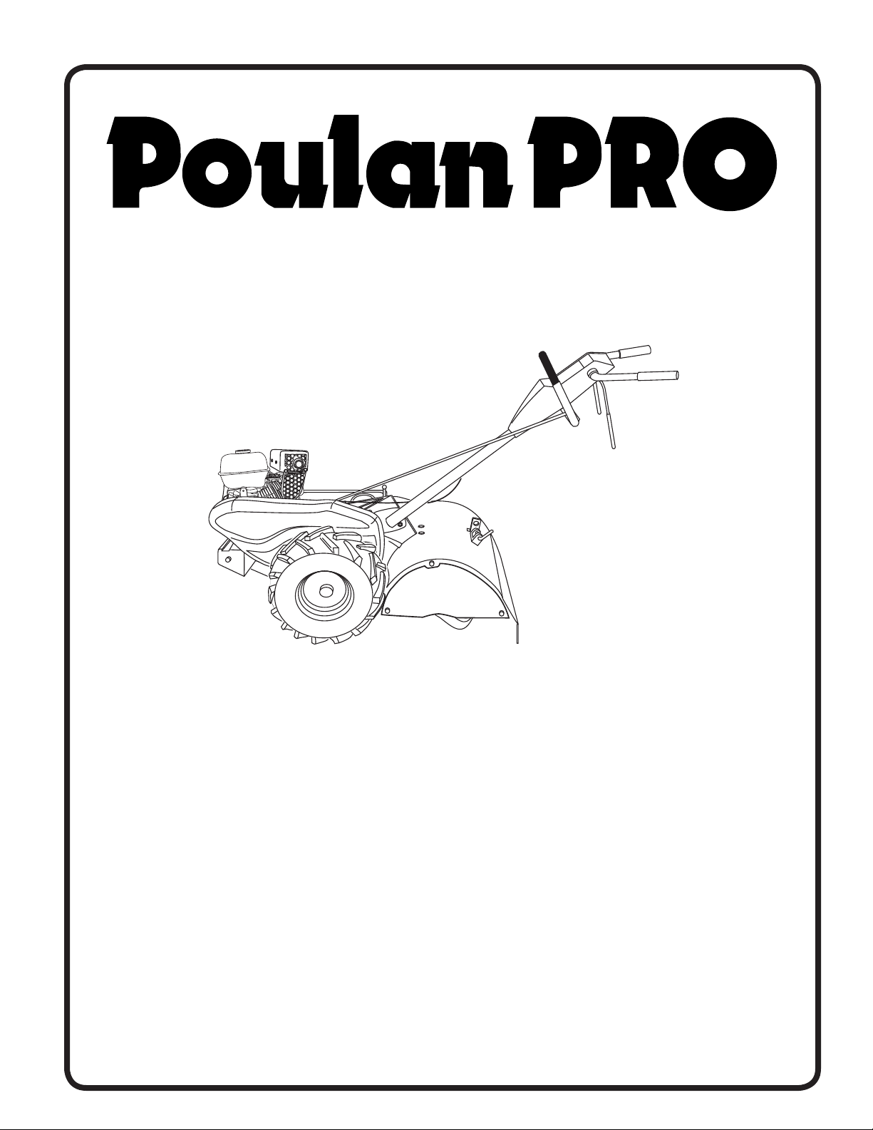
IMPORTANT MANUAL Do Not Throw Away
REPAIR PARTS MANUAL
MODEL:
RT900
REAR TINE TILLER
ALWAYS WEAR EYE PROTECTION DURING OPERATION
Visit our website: www.poulan-pro.com
532 44 01-96 Rev. 1
Page 2

FRONT TINE TILLER - - MODEL NUMBER RT900 (MFG. ID. NO. 96092002600)
HANDLE ASSEMBLY
8
6
2
30
10
2
33
14
12
13
11
41
27
29
37
37
4
24
23
KEY PART
NO. NO. DESCRIPTION
2 532 42 76-43 Grip, Handle
4 532 15 92-28 Bar Assembly, Control
6 532 18 06-87 Panel, Control
8 871 19 10-08 Screw, Phd. #10-24
10 532 12 47-97 Grip, Handle
11 532 12 47-88 Clip, Hairpin
12 532 08 13-28 Bolt, Shoulder
13 532 18 74-97 Handle, Shift
14 532 10 93-13 Grommet, Rubber
15 532 10 93-37 Rod, Shift
16 872 11 06-08 Bolt, Carriage 3/8-16 x 1 Gr. 5
17 532 10 92-29 Lock, Handle
18 873 68 06-00 Nut, Crownlock 3/8-16 unc
19 819 13 16-11 Washer 13/32 x 1 x 11 Ga.
20 532 10 92-28 Lever, Lock, Handle
26
27
15
21
16
20
KEY PART
NO. NO. DESCRIPTION
21 532 18 05-17 Handle
23 532 08 67-77 Screw, Hex Washer Hd. Slotted
#10-24 x 1/2
24 532 00 94-84 Clip
26 532 15 92-31 Cable, Clutch
27 873 90 04-00 Nut, Hex Flange 1/4-20 unc
29 873 73 10-00 Nut, Keps #10-24 unc
30 532 10 41-64 Tie, Cable
31 532 15 06-96 Bolt, Pivot
33 872 14 04-04 Bolt, Carriage 1/4-20 unc x 1/2
37 532 10 26-04 Grip, Bar, Control
41 532 10 27-44 Clamp, Bar, Control
NOTE: All component dimensions are given in U.S. inches.
1 inch = 25.4 mm
19
18
17
31
Handle_assy_99_23
2
11
Page 3

FRONT TINE TILLER - - MODEL NUMBER RT900 (MFG. ID. NO. 96092002600)
MAINFRAME, LEFT SIDE
7
6
39
65
68
68
13
65
37
36
67
34
31
5
33
14
32
29
22
30
66
28
9
8
10
12
21
69
3
4
38
16
19
69
27
40
23
KEY PART
NO. NO. DESCRIPTION
3 873 22 06-00 Nut, Hex 3/8-16
4 532 43 24-20 Shield, Inner Belt Guard RT
5 532 16 43-29 Screw, Shift Lever
6 532 11 01-11 Lever, Shift
7 872 11 04-04 Bolt, Carriage 1/4-20 x 1/2 Gr. 5
8 532 00 87-00 Plate, Shift Indicator
9 532 08 67-77 Screw, Hex, Washer Head, Slotted
#10-24 x 1/2
10 532 00 94-84 Clip
12 873 51 04-00 Nut, Keps Hex 1/4-20 unc
13 823 23 05-06 Screw, Set, Hex 5/16-18 x 3/8
14 532 15 61-17 Spacer, Split 0.327 x 0.42 x 1.220
15 819 11 11-16 Washer 11/32 x 11/16 x 16 Ga.
16 532 14 51-02 Sheave, Transmission
19 812 00 00-28 Retainer, Ring
21 532 11 06-52 Spacer, Split 0.327 x 0.42 x 2.09
22 874 77 05-08 Bolt, Fin Hex 5/16-24 unf x 1/2
23 532 10 21-90 Tire
532 44 18-09 Rim
532 12 47-18 Tire, Valve
24 532 12 68-75 Rivet, Drilled
25 532 12 47-88 Clip, Hairpin
26 532 44 17-18 Guard, Belt
44
40
26
15
mainframe_left_25
24
25
KEY PART
NO. NO. DESCRIPTION
27 532 13 28-01 Belt, V
28 532 10 46-79 Pulley, Idler
29 812 00 00-32 Ring, Klip
30 532 15 92-29 Bracket, Idler
31 532 10 21-94 Bolt, Fin Hex 3/8-16 unc x 10
32 532 10 21-41 Shaft, Idler Arm
33 874 76 06-16 Bolt, Hex 3/8-16 x 1
34 532 10 21-73 Counterweight, L. H.
36 532 10 23-31 Bracket, Reinforcement, L. H.
37 532 13 08-12 Sheave, Engine
38 874 76 05-44 Bolt, Fin Hex 5/16-18 unc x 2-3/4
39 532 14 00-62 Cap, Plunger Blk
40 532 17 04-88 Screw, Hex Wsh Slt #10-24 x 1/2
44 873 80 05-00 Nut, Lock Hex w/Ins 5/16-18 unc PL
65 873 97 05-00 Nut, Lock Hex Flange
66 819 13 13-12 Washer 13/32 x 13/16 x 12 Ga.
67 874 76 05-24 Bolt, Fin Hex 5/16-18 unc x 1-1/2
68 873 51 06-00 Nut, Keps Hex 3/8-16 unc
69 532 16 41-73 Keeper, Belt
NOTE: All component dimensions are given in U.S. inches.
1 inch = 25.4 mm
3
Page 4
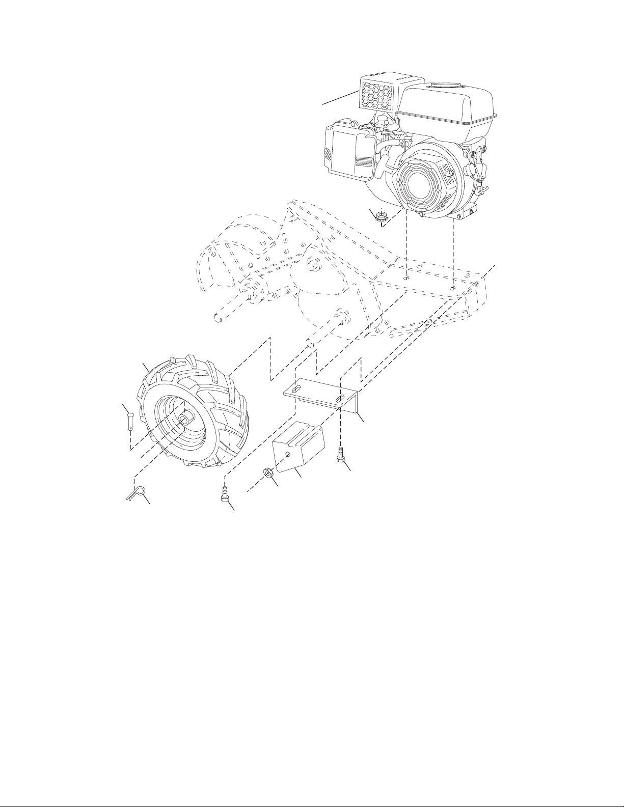
FRONT TINE TILLER - - MODEL NUMBER RT900 (MFG. ID. NO. 96092002600)
MAINFRAME, LEFT SIDE
MAINFRAME?RIGHT?,#4?
KEY PART
NO. NO. DESCRIPTION
2 873 97 05-00 Locknut, Hex, Flange 5/16-18
5 532 10 23-32 Bracket Reinforcement RH
7 532 10 21-73 Counter Weight,
10 874 76 05-24 Bolt, Hex 5/16-18 x 1-1/2
11 532 12 47-88 Clip, Hairpin
12 532 12 68-75 Rivet, Drilled
13 532 10 21-90 Tire
532 44 18-09 Rim
532 12 47-18 Tire Valve
15 - - - - - - - - Engine, LCT PLMHK14600124P
(Order parts from engine manufacturer)
44 873 51 06-00 Nut, Keps, Hex 3/8-16 unc
NOTE: All component dimensions are given in U.S. inches.
1 inch = 25.4 mm
4
Page 5

FRONT TINE TILLER - - MODEL NUMBER RT900 (MFG. ID. NO. 96092002600)
TRANSMISSION
11
12
13
15
9
52
25
10
9
8
5
7
6
5
4
24
3
35
53
44
2
18
27
19
20
28
21
50
22
29
14
37
38
23
18
32
36
16
30
18
33
31
37
40
39
34
61
18
18
41
48
49
42
60
25
24
44
43
53
transmission_21
51
58
KEY PART
NO. NO. DESCRIPTION
1 532 18 85-54 Transmission Assembly
(In cludes Key Nos. 2-53)
2 532 18 84-82 Gearcase, L.H. w/Bearing
(In cludes Key No. 4)
3 532 43 10-22 Gasket, Gearcase
4 532 00 50-20 Bearing, Needle
5 532 00 13-70 Washer, 5/8 x 1.10 x 1/32
6 532 13 73-35 Pinion, Input
7 532 14 51-01 Shaft, In put
8 532 12 47-92 Bearing, Needle
9 532 15 44-67 Washer, Seal
10 532 12 46-97 Ball, Steel
11 532 10 03-71 Spring, Shift, Fork
12 532 10 61-60 O-Ring
13 532 14 21-45 Asm. Bracket Shift
14 532 00 83-53 Fork, Shift
15 812 00 00-39 Ring, Klip
16 532 15 44-66 Shaft, Shift
18 532 00 43-58 Washer
19 812 00 00-40 Ring, Klip
20 532 10 21-14 Gear, As sem bly, Reverse Idler
(Includes Key Nos. 21 and 22)
21 532 10 21-15 Gear, Re verse Idler
22 532 00 68-03 Bearing, Needle
23 532 10 21-11 Shaft, Re verse Idler
24 810 04 07-00 Washer, Lock 7/16
25 873 61 07-00 Nut, Hex 7/16-20
27 532 14 30-09 Bearing, Shaft, Ground Drive L.H.
28 532 10 63-90 Spacer 0.765 x 1.125 x 1.23
29 532 10 21-34 Chain #35-50 Pitch
KEY PART
NO. NO. DESCRIPTION
30 532 15 07-37 Ground Shaft Assembly
31 532 14 30-08 Bearing, Shaft, Ground Drive R.H.
32 532 10 63-88 Spacer 0.70 x 1.00 x 1.150
33 532 10 21-21 Sprocket and Gear Assembly
34 532 10 21-12 Shaft, Re duc tion (2nd)
35 532 10 21-01 Screw, Whiz, Lock 5/16-18 x 3-1/2
36 532 15 43-55 Sprocket Assembly w/Bearing
(Includes Key Nos. 37 and 38)
37 532 12 47-91 Bearing, Needle
38 532 15 43-56 Sprocket, Tine
39 532 10 53-45 Gear, Clus ter, Red 1st & 2nd
40 532 10 53-46 Gear, Re verse
41 532 00 83-58 Shaft, Re duc tion (1st)
42 532 00 42-20 Washer, Thrust
43 532 10 61-46 Spacer 1.01 x 1.75 x 0.760
44 532 15 52-36 Seal Asm, Oil
48 532 18 84-85 Gearcase, R.H. w/Bearing
(In cludes Key No. 8)
49 532 43 14-85 Shaft, Tine
50 532 10 61-47 Chain, Roller #50-50 Pitch
51 817 72 04-08 Screw 1/4-20 x 1/2
52 873 22 05-00 Nut, Hex 5/16-18
53 532 16 51-40 Kit, Bearing
58 532 17 95-20 Bolt Shoulder
60 532 18 32-26 Fitting Grease
61 532 43 10-15 Spacer 1.015 x 1.50 x .650
- - 532 00 60-66 Grease, Plastilube #1
NOTE: All component dimensions are given in U.S. inches.
1 inch = 25.4 mm
5
Page 6

FRONT TINE TILLER - - MODEL NUMBER RT900 (MFG. ID. NO. 96092002600)
TINE SHIELD
27
24
23
16
26
28
25
33
29
32
3
23
4
18
5
24
22
21
5
6
7
23
20
19
8
13
5
9
5
16
29
14
14
1
TINE?SHIELD??IN?R
KEY PART
NO. NO. DESCRIPTION
3 532 00 83-93 Pin, Stake, Depth
4 812 00 00-35 Ring, Klip
5 532 18 08-47 Bolt 5/16-18 x 3/4 ZNC
6 532 00 83-94 Spring
7 532 00 83-92 Bracket, Latch
8 532 10 92-30 Spring, Depth Stake
9 532 44 18-41 Shield, Tine
13 872 11 05-10 Bolt, Carriage 5/16-18 x 1-1/4
14 532 12 43-43 Bracket, Shield Tine
16 873 90 04-00 Nut, Hex Flange 1/4-20 unc
18 872 04 04-10 Bolt, Carriage 1/4-20 x 1-1/4 Gr. 5
19 532 10 27-01 Grip
20 873 22 06-00 Nut, Hex 3/8-16
21 532 10 21-56 Stake, Depth
22 874 93 06-32 Bolt, Hex 3/8-16 x 2
KEY PART
NO. NO. DESCRIPTION
23 532 00 44-40 Hinge
24 872 14 04-04 Bolt, Carriage 1/4-20 x 1/2 Gr. 5
25 532 12 47-17 Cap, Vinyl
26 532 10 92-27 Pad, Idler
27 532 44 18-13 Shield, Leveling
28 532 12 05-88 Pin, Hinge
29 532 44 18-11 Shield, Side
30 873 97 05-00 Nut Lock Hex Flange
32 873 22 04-00 Nut Fin Hex 1/4-20 unc
33 810 04 04-00 Washer Lock Hvy Helical 1/4
38 873 51 05-00 Nut, Keps 5/16-18 unc
NOTE: All component dimensions are given in U.S. inches.
1 inch = 25.4 mm
6
Page 7

FRONT TINE TILLER - - MODEL NUMBER RT900 (MFG. ID. NO. 96092002600)
TINE ASSEMBLY
KEY PART
NO. NO. DESCRIPTION
1 532 00 44-59 Tine, Outer, L.H.
2 532 13 26-73 Clevis Pin
3 532 00 65-54 Tine, Inner, L.H.
4 532 12 46-60 Retainer, Spring Zinc
5 532 13 27-21 Assembly, Hub and Plate, L.H.
8 874 61 06-16 Bolt, Hex 3/8-24 x 1
9 532 00 44-60 Tine, Outer, R.H.
TINE?IPB???R
KEY PART
NO. NO. DESCRIPTION
10 532 13 27-22 Assembly, Hub and Plate, R.H.
11 532 00 65-55 Tine, Inner, R.H.
34 873 54 06-00 Nut Crownlock 3/8-24
NOTE: All component dimensions given in U.S. inches.
1 inch = 25.4 mm
7
Page 8

FRONT TINE TILLER - - MODEL NUMBER RT900 (MFG. ID. NO. 96092002600)
DECALS
1
2
4
13
5
7
9
KEY PART
NO. NO. DESCRIPTION
1 532 17 31-96 Decal, CNTRL PNL
2 532 43 22-25 Decal, Blt Grd
4 532 40 15-57 Decal, Control, Panel Oper.
5 532 11 06-14 Decal, Hand Placement
6 532 10 21-80 Decal, Shift Indicator
7 532 42 29-72 Decal, Caution
9 532 12 00-76 Decal, Warning, Rotating Tines
13 532 42 03-32 Decal, Engine Tank
- - 532 44 01-88 Manual, Operator's, English/French
- - 532 44 01-96 Manual, Repair Parts, English
6
8
Page 9

SERVICE NOTES
9
Page 10

SERVICE NOTES
10
Page 11

SERVICE NOTES
11
Page 12

PARTS AND SERVICE
This product has been expertly en gi neered and carefully manu fac tured to rigid quality stan dards. As with all
mechanical products, some adjustments or part replacement may be necessary during the life of your unit.
For Parts and service, contact our authorized distributor: call 1-800-849-1297
• For replacement parts, have available the following information:
a. Model Number/Manufacturer's I.D. Number
b. Description of part.
For Technical Assistance: call 1-800-829-5886
For a Parts Manual, go to our website: www.poulan-pro.com/support.asp
NOTE: HOP provides parts and service through its au thor ized dis tribu tors and dealers; there fore,
all requests for parts and service should be directed to your local dealer(s). The phi loso phy
of HOP is to con tinu ally improve all of its prod ucts. If the operating characteristics or the
appearance of your product differs from those described in this Manual, please contact your
local dealer for updated in for ma tion and as sis tance.
02.22.11 TH/CL Printed in U.S.A.
 Loading...