

Page 1
IMPORTANT MANUAL DO NOT THROW AWAY
REPAIR PARTS MANUAL
MODEL:
WARNING:
Read this Man u al and follow all Warnings
and Safety Instructions. Fail ure to do so
can re sult in serious in ju ry.
PXT12538
LAWN TRACTOR
ALWAYS WEAR EYE PROTECTION DURING OPERATION
Visit our website: www.poulan-pro.com
5000
431150 Rev. 3
06.16.10 JA Printed in the U.S.A.
Page 2

HOW TO USE THIS MANUAL
This manual is designed to provide the customer with a means to identify the parts on his/her tractor
when ordering repair parts. The illustrations may or may not represent the actual assemblies; therefore,
it is not recommended to use this manual as a guide to assemble or disassemble the tractor. Some
hardware and parts are drawn larger in order to more readily identify them.
Each tractor has its own model number.
The model number for your tractor can be found on the fender under the seat.
When ordering parts, always give the following information:
• Product - “TRACTOR”
• MODEL NUMBER - “PXT12538 (96016002200)”
• Part Number
• Part Description
TABLE OF CONTENTS
SCHEMATIC ................................................................................................................ 3
ELECTRICAL ............................................................................................................ 4-5
CHASSIS ..................................................................................................................6-7
DRIVE........................................................................................................................8-9
ENGINE ................................................................................................................. 10-11
STEERING ............................................................................................................12-13
DECALS ..................................................................................................................... 14
SEAT .......................................................................................................................... 15
MOWER DECK .....................................................................................................16-17
MOWER LIFT ............................................................................................................. 18
WARRANTY ............................................................................................................... 20
2
Page 3
TRACTOR - - MODEL NO. PXT12538 (96016002200), PRODUCT NO. 960 16 00-22
38
38
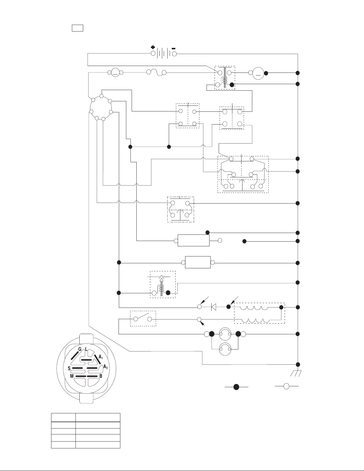
SCHEMATIC
SCH03
BATTERY
DIONELOS
RED
AMMETER
(OPTIONAL)
S
B
M
A1
G
L
A2
RED
A
RED
FUSE
WHITE
BLUE
BLACK
CLUTCH / BRAKE
(PEDAL UP)
BLACK
ATTACHMENT CLUTCH
(CLUTCH OFF)
(NOT OCCUPIED)
STARTER
M
BLACK
SEAT SWITCH
BLACK
BLUE
RED
LIGHT SWITCH
REVERSE SWITCH
NOT IN REVERSE
BLACK
BLACK/WHITE
BLUE
FUEL
LINE
FUEL SHUT-OFF
SOLENOID
LIGHTING SYSTEM OUTPUT
5 AMP AC @ 3600 RPM
ORANGE
BROWN
GRAY
IGNITION
UNIT
ON TWIN CYL. ENGINES)
HOUR
METER
(OPTIONAL)
CHARGING SYSTEM OUTPUT
3 AMP DC @ 3600 RPM
DIODE
14 VOLTS AC MIN. @ 3600 RPM (LIGHTS OFF)
SHORTING CONNECTOR
BLACK
SPARK PLUGS
GAP
(2 PLUGS
BLACK
28 VOLTS AC MIN. @ 3600 RPM
(CHARGING SYSTEM DISCONNECTED)
STATOR
GRAY
BLACK
IGNITION SWITCH
CIRCUITPOSITION
OFF
RUN/OVERRIDE
M+G+A1
B+S+A1START
B+A1
B+A1RUN
“MAKE”
L+A2
NOTE
YOUR TRACTOR IS
EQUIPPED WITH A SPECIAL
ALTERNATOR SYSTEM.
THE LIGHTS ARE NOT
CONNECTED TO THE
BATTERY, BUT HAVE THEIR
OWN ELECTRICAL SOURCE.
BECAUSE OF THIS, THE
BRIGHTNESS OF THE LIGHTS
WILL CHANGE WITH ENGINE
SPEED. AT IDLE THE LIGHTS
WILL DIM. AS THE ENGINE IS
SPEEDED UP, THE LIGHTS
WILL BECOME THEIR BRIGHTEST.
3
HEADLIGHTS
NON-REMOVABLE
CONNECTIONS
REMOVABLE
CONNECTIONS
WIRING INSULATED CLIPS
NOTE: IF WIRING INSULATED CLIPS
WERE REMOVED FOR SERVICING OF
UNIT, THEY SHOULD BE RE-INSTALLED
TO PROPERLY SECURE YOUR WIRING.
Page 4
L02
30
33
34
22
79
21
26
90
42
43
27
41
25
24
28
16
16
29
94
92
2
40
93
TRACTOR - - MODEL NO. PXT12538 (96016002200), PRODUCT NO. 960 16 00-22
32
32
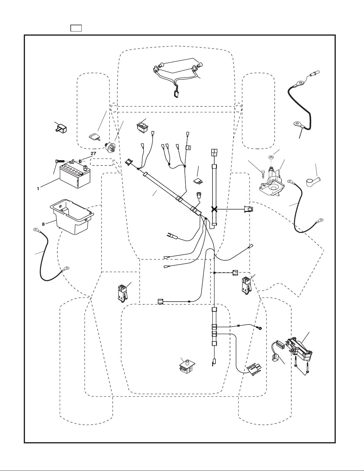
ELECTRICAL
4
Page 5

TRACTOR - - MODEL NO. PXT12538 (96016002200), PRODUCT NO. 960 16 00-22
32
32
ELECTRICAL
KEY PART
NO. NO. DESCRIPTION
1 163465 Battery
2 74760412 Bolt Hex Hd 1/4-20 unc x 3/4
8 176689 Box Battery
16 176138 Switch Interlock
21 175688 Harness Asm Light w/4152j
22 4152J Bulb Light #1156
24 421299 Cable Battery 6 Ga. 11" Red
25 421297 Cable Battery
26 175158 Fuse 20 AMP
27 73510400 Nut Keps Hex 1/4-20 unc
28 421298 Cable Ground 6 Ga. 12" Black
29 192749 Switch Seat
30 193350 Switch Ign
33 411935 Key/Chain
34 110712X Switch Light/Reset
40 197428 Harness Ign
41 71110408 Bolt Blk Fin Hex 1/4-20
42 131563 Cover Terminal Red
43 192507 Solenoid
79 175242 Socket Asm. Bulb Twistlock
90 180449 Cover Terminal Battery
92 196615 Harness Pigtail
93 192540 Screw Plastite 10-14 x 2.0
94 191834 Module Reverse ROS
NOTE: All component dimensions given in U.S. inches
1 inch = 25.4 mm.
5
Page 6
TRACTOR - - MODEL NO. PXT12538 (96016002200), PRODUCT NO. 960 16 00-22
39
39
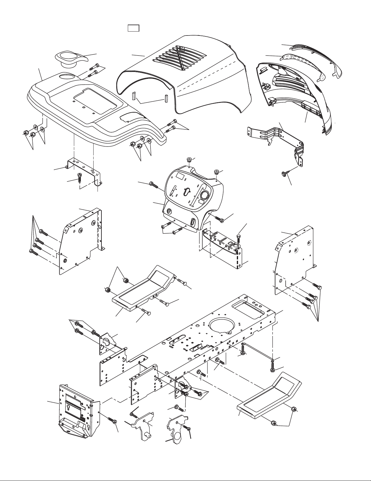
CHASSIS AND ENCLOSURES
#HASSISSTLT?!LPHA??R
6
Page 7

TRACTOR - - MODEL NO. PXT12538 (96016002200), PRODUCT NO. 960 16 00-22
39
39
CHASSIS AND ENCLOSURES
KEY PART
NO. NO. DESCRIPTION
1 174619 Chassis
2 176554 Drawbar, Stretch
5 155272 Bumper, Hood/Dash
9 428394X010 Dash
10 72140608 Bolt, Carriage 3/8-16 x 1
11 174996 Panel Dash LH
13 172105X010 Panel Slkscr Dash RH
17 187559X505 Hood
18 184921 Bumper Hood
24 74780616 Bolt Fin Hex 3/8-16 unc x 1 Gr. 5
25 19131312 Washer 13/32 x 13/16 x 12 Ga.
26 73800600 Nut Lock Hex w/Ins 3/8-16 unc
28 187565X428 Grille
29 187567X599 Lens Grille Bar
30 192528X505 Fender
31 136619 Bracket Fender Repl 109873X
33 179716X505 Footrest Pnt LH
34 179717X505 Footrest Pnt RH
35 72110606 Bolt Rdhd Sht Sqnk 3/8-16 x 3/4
37 17490508 Screw Thdrol 5/16-18 x 1/2 TYT
38 175710 Bracket Asm. Pivot Mower
39 187568 Bracket Pivot
64 154798 Dash Lower
142 175702 Plate Reinforcement
145 409167 Rod Pivot Chassis/Hood
159 169473X428 Cupholder
205 17490608 Screw Thdrol 3/8-16 x 1/2
207 17670508 Screw 5/16-18 x 1/2
208 17670608 Screw Thdrol 3/8-16 x 1/2
209 17000612 Screw Hex Wsh Thdrol 3/8-16
212 187569 Insert Lens Reflect
278 416358 Screw #10 x 0.750 BOS Thread
--- 5479J Plug Button Blk 359 Dia Choke
- - 187801 Plug Dome Plastic
NOTE: All component dimensions given in U.S. inches
1 inch = 25.4 mm.
7
Page 8

TRACTOR - - MODEL NO. PXT12538 (96016002200), PRODUCT NO. 960 16 00-22
40
40
DRIVE
89
120
57
77
13
112
16
14
69
197
84
11
52
80
85
30
32
308
85
10
8
170
21
63
120
81
159
51
52
14
82
5
6
308
158
165
18
162
83
156
62
168
166
35
56
41
38
39
37
36
34
161
198
169
18
4
3
6
79
6
112
163
113
32
30
66
65
64
50
27
49
47
120
70
116
55
202
150
48
151
51
15
96
26
25
24
19
26
26
2
77
1
75
74
78
76
29
28
22
26
36
10
drive-stlt_Peerless_fender_18
35
53
27
8
Page 9

TRACTOR - - MODEL NO. PXT12538 (96016002200), PRODUCT NO. 960 16 00-22
40
40
DRIVE
KEY PART
NO. NO. DESCRIPTION
1 - - - - - - Transaxle Peerless 206-545C
2 146682 Spring Return Brake T/a Zinc
3 123666X Pulley Transaxle 18" Tires
4 12000028 Ring Retainer # 5100-62
5 121520X Strap Torque 30 Degrees
6 17060512 Screw 5/16-18 x 3/4
8 192706 Rod Shift Fender Adjust Lt
10 76020416 Pin Cotter 1/8 x 1 Cad
11 105701X Washer Plate Shf 388 Sq Hole
13 74550412 Bolt 1/4-28 unf Gr. 8 w/Patch
14 10040400 Washer Lock Hvy Helical
15 74490560 Bolt Hex FLGHD 5/16-18 x 3.75
16 73800500 Nut Lock Hex w/ins 5/16-18
18 74780616 Bolt, Fin Hex 3/8-16 unc x 1 Gr. 5
19 73800600 Nut Lock 3/8-16 unc
21 106933X Knob
22 130804 Rod Brake
24 73350600 Nut Hex Jam 3/8-16 unc
25 106888X Spring Rod Brake 2 00 Zinc
26 19131316 Washer 13/32 x 13/16 x 16 Ga.
27 76020412 Pin Cotter 1/8 x 3/4 Cad
28 175765 Rod Brake Parking LT/YT
29 71673 Cap Brake Parking
30 174973 Bracket Mtg Transaxle
32 74760512 Bolt Hex Hd 5/16-18 unc x 3/4
34 175578 Shaft Asm Pedal Foot
35 120183X Bearing Nylon Blk 629 Id
36 19211616 Washer 21/32 x 1 x 16 Ga.
37 1572H Pin Roll 3/16 x 1"
38 179114 Pulley Composite Flat
39 72110622 Bolt RDHD 3/8-16 unc x 2-3/4 Gr. 5
41 175556 Keeper Belt Flat Idler
47 127783 Pulley Idler V Groove Plastic
48 154407 Bellcrank Asm
49 123205X Retainer Belt Style Spring
50 72110612 Bolt Carr. Sh. 3/8-16 x 1-1/2 Gr. 5
51 73680600 Nut Crownlock 3/8-16 unc
52 73680500 Nut Crownlock 5/16-18 unc
53 199652 Link Clutch
55 105709X Spring Return Clutch 6 75
56 17060620 Screw 3/8-16 x 1-1/4
57 138255 V-Belt Ground Drive
62 8883R Cover Pedal Blk Round
63 175410 Engine Pulley
64 173937 Bolt Hex
KEY PART
NO. NO. DESCRIPTION
65 10040700 Washer Lock Hvy Hlcl Spr 7/16
66 154778 Keeper Belt Engine Foolproof
69 142432 Screw Hex wsh HiLo 1/4 x 1/2 unc
70 134683 Guide Belt Mower Drive RH
74 137057 Spacer Axle
75 121749X Washer 25/32 x 1 1/4 x 16 Ga.
76 12000001 E-ring #5133-75
77 123583X Key Square 2 0 x 1845/ 1865
78 121748X Washer 25/32 x 1-5/8 x 16 Ga.
79 2228M Key Woodruff #9 3/16 x 3/4
80 131486 Arm Shift
81 165594 Shaft Asm Cross Tapered PMST/20
82 165711 Spring Torsion T/a
83 19171216 Washer 17/32 x 3/4 x 16 Ga.
84 166228 Link Transaxle
85 150360 Nut Lock Center 1/4 - 28 FNTHD
89 192053X428 Console Shift STLT
96 4497H Retainer Spring 1"
112 19091210 Washer 9/32 x 3/4 x 10 Ga.
113 127285X Strap Torque LT
116 72140608 Bolt Rdhd Sq Neck 3/8-16 x 1
120 73900600 Nut Lock Flg. 3/8-16 unc
150 175456 Spacer Retainer
151 19133210 Washer 13/32 x 2 x 10
156 166002 Washer Srrted 5/16ID x 1.125
158 165589 Bracket Shift Mount
159 183900 Hub Tapered Flange Shift Lt
161 72140406 Bolt Rdhd Sqnk 1/4-20 x 3/4
162 73680400 Nut Crownlock 1/4-20 unc
163 74780416 Bolt Hex Fin 1/4-20 unc x 1 Gr. 5
165 165623 Bracket Pivot Lever
166 17490510 Screw 5/16-18 x 5/8
168 165492 Bolt Shoulder 5/16-18 x .561
169 165580 Plate Fastening
170 187414 Keeper Belt Transaxle Gear
197 169613 Nyliner Snap-In
198 169593 Washer Nyliner
202 72110614 Bolt RdHd 3/8-16 unc x 1-3/4 Gr. 5
308 195785 Spacer Transaxle
NOTE: All component dimensions given in U.S. inches
1 inch = 25.4 mm
9
Page 10

TRACTOR - - MODEL NO. PXT12538 (96016002200), PRODUCT NO. 960 16 00-22
24
24
ENGINE
2
1
3
72
32
31
44
46
78
37
33
23
122
81
45
13
4
78
40
29
33
OPTIONAL EQUIPMENT
Spark Arrester
engine-stlt_bs_15
10
Page 11

TRACTOR - - MODEL NO. PXT12538 (96016002200), PRODUCT NO. 960 16 00-22
24
24
ENGINE
KEY PART
NO. NO. DESCRIPTION
1 170551 Control Th/ch Flag
2 17720408 Screw Hex Thd Cut 1/4-20 x 1/2
3 - - - - - - - - Engine, B&S 219807-0389-B1
4 179758 Muffler Exhaust B&S
13 165291 Gasket Eng 1 313 Id Tin Plated
23 169837 Shield BRN/DBR Guard
29 137180 Kit Spark Arrester (Flat Scrn)
31 407545 Tank Fuel Front
32 425162 Cap Asm Fuel
33 123487X Clamp Hose
37 401137 Line Fuel
40 124028X Bushing Snap Nyl Blk Fuel Line
44 17670412 Screw Thdrol 1/4-20 x 3/4
45 17000612 Screw Hex Wsh Thdrol 3/8-16
46 19091416 Washer 9/32 x 7/8 x 16 Ga.
72 192334 Screw Socket Head 5/16-18 x 3/4
78 17060620 Screw 3/8-16 x 1-1/4
81 73510400 Nut Keps Hex 1/4-20 unc
122 421922 Extension Drain Oil
NOTE: All component dimensions given in U.S. inches
1 inch = 25.4 mm
For engine service and replacement parts, call the toll free
number for your engine manufacturer listed below:
Briggs & Stratton 1-800-233-3723
Engine Power Rating Information
The gross power rating for individual gas engine models is labeled in accordance with SAE (Society of Automotive
Engineers) code J1940 (Small Engine Power & Torque Rating Procedure), and rating performance has been obtained
and corrected in accordance with SAE J1995 (Revision 2002-05). Torque values are derived at 3060 RPM; horsepower
values are derived at 3600 RPM. Actual gross engine power will be lower and is affected by, among other things, ambient operating conditions and engine-to-engine variability. Given both the wide array of products on which engines are
placed and the variety of environmental issues applicable to operating the equipment, the gas engine will not develop
the rated gross power when used in a given piece of power equipment (actual “on-site” or net power). This difference is
due to a variety of factors including, but not limited to, accessories (air cleaner, exhaust, charging, cooling, carburetor,
fuel pump, etc.), application limitations, ambient operating conditions (temperature, humidity, altitude), and engine-toengine variability. Due to manufacturing and capacity limitations, Briggs & Stratton may substitute an engine of higher
rated power for this Series engine.
11
Page 12

TRACTOR - - MODEL NO. PXT12538 (96016002200), PRODUCT NO. 960 16 00-22
41
41
STEERING ASSEMBLY
38
97
34
39
41
42
37
37
1
36
44
91
43
29
88
68
17
29
71
82
67
67
4
43
43
65
8
32
68
13
46
9
6
7
9
5
46
8
6
9
2
7
9
5
40
26
3
11
Steering-lt_OPP_1
15
29
10
12
28
30
95
8
Page 13

TRACTOR - - MODEL NO. PXT12538 (96016002200), PRODUCT NO. 960 16 00-22
41
41
STEERING ASSEMBLY
KEY PART
NO. NO. DESCRIPTION
1 186780 Wheel Steering
2 418168 Axle Asm
3 169840 Spindle Asm LH
4 169839 Spindle Asm RH
5 6266H Washer Thrust .75 x 1.230
6 121748X Washer 25/32 x 1-5/8 x 16 Ga.
7 19272016 Washer 27/32 x 1-1/4 x 16 Ga.
8 12000029 Ring Klip #t5304-75
9 3366R Bearing Col Strg Blk
10 175121 Link Drag
11 10040600 Washer Lock Hvy Hlcl Spr 3/8
13 136518 Spacer Brace Axle
15 73900600 Lock Nut Flg. 3/8-16 unc
17 411386 Shaft Asm Strg
26 126847X Bushing Link Drag Blk LR
28 19131416 Washer 13/32 x 7/8 x 16 Ga.
29 17000612 Screw 3/8-16 x 3/4
30 76020412 Pin Cotter 11/32 ID x 2 3/8 OD x 12 Ga.
32 192757 Rod Tie Wire Form 19 75 Mech
34 10040500 Washer Lock 5/16
36 155099 Bushing Strg 5/8 Id Dash
37 152927 Screw
38 192916 Cap Wheel Steer
39 19113812 Washer 11/32 x 2 3/8 OD x 12 Ga.
40 73540600 Nut Crownlock 3/8-24
41 186737 Adaptor Wheel Strg
42 145054X428 Boot Dash Mtl Steering Blk
43 121749X Washer 25/32 x 1 1/4 x 16 Ga.
44 190752 Extension Steering
46 121232X Cap Spindle Fr Top Blk
65 414736 Spacer Brace Axle
67 72110618 Bolt RDHD SQNK 3/8-16 x 2-1/4
68 169827 Brace Axle
71 175146 Steering Asm.
82 199978 Bracket Susp Chassis Front
88 175118 Bolt Shoulder 7/16-20
91 175553 Clip Steering
95 188967 Washer Harden .793 x 1.637 x 060
97 428982 Bolt Fin Hx 5/16-18 x 4 w/Patch
NOTE: All component dimensions given in U.S. inches
1 inch = 25.4 mm.
13
Page 14

TRACTOR - - MODEL NO. PXT12538 (96016002200), PRODUCT NO. 960 16 00-22
27
27
DECALS
7
9
12
8
3
10
8
4
2
12
6
5
15
KEY PART
NO. NO. DESCRIPTION
2 405121 Decal, Replacement
3 408808 Decal, Engine HP
4 170563 Decal, Warning
5 431375 Decal, Fender Service
6 411658 Decal, Fender Warning
7 437373 Decal, Ins Str Wh
8 431237 Decal, Side Panel
9 429169 Decal, Fender
10 194302 Decal, V-Belt Sch.
WHEELS & TIRES
1
2
6
5,8
4,10
7
3,9
11
KEY PART
NO. NO. DESCRIPTION
12 429170 Decal, Hood
15 145005 Decal, Caution, Battery
- - 179769X428 Pad Foot Rest RH
- - 179768X428 Pad Foot Rest LH
- - 138311 Decal, Handle Lft Height Adj.
- - 431147 Manual, Operator's, English/French
- - 431148 Manual, Operator's, Spanish
- - 431150 Manual, Parts, English/French
KEY PART
NO. NO. DESCRIPTION
1 59192 Cap, Tire Valve
2 65139 Stem, Valve
3 123410X Tire, Front
4 421652 Tube, Front (Service item only)
5 421554X643 Rim Assembly, 6" Front
6 278H Fitting, Grease (Front wheel only)
7 9040H Bearing, Flange (Front wheel only)
8 421533X643 Rim Assembly, 8" Rear
9 106230X Tire, Rear
10 7154J Tube, Rear (Service item only)
11 104757X643 Cap, Hub Axle
- - 144334 Sealant, Tire (10 oz. Tube)
wheel_1
NOTE: All component dimensions given in U.S. inches
1 inch = 25.4 mm
14
Page 15

TRACTOR - - MODEL NO. PXT12538 (96016002200), PRODUCT NO. 960 16 00-22
42
42
SEAT ASSEMBLY
1
8
14
16
24
26
25
10
5
9
8
9
7
7
5
6
22
2
21
15
23
13
17
seat_lt.bolt_9
KEY PART
NO. NO. DESCRIPTION
1 424035 Seat
2 140551 Bracket Seat Pivot
3 71110616 Bolt Hex 3/8 - 16 x 1
4 19131610 Washer 13/32 x 1 x10 Ga.
5 145006 Clip Push-In Hinged
6 73800600 Nut Lock Hex w/Ins 3/8 - 16
7 124181X Spring Seat Cprsn 2 250 Blk Zi
8 17000616 Screw 3/8-16 x 1.5
9 19131614 Washer 13/32 x 1 x 14 Ga.
10 195530 Pan Pnt Seat
12 174648 Bracket Pnt Mounting Switch
13 121248X Bushing Snap Blk Nyl
14 72050412 Bolt Rdhd Sht Nk 1/4 - 20 x 1 -1/2
12
4
3
KEY PART
NO. NO. DESCRIPTION
15 134300 Spacer Split .28 x .96
16 121250X Spring Cprsn
17 123976X Nut Lock 1/4 Lge Flg
21 171852 Bolt Shoul der 5/16-18 unc-2A
22 73800500 Nut Lock Hex w/Ins 5/16 - 18
23 71110814 Bolt Hex
24 19171912 Washer 17/32 x 1-3/16 x 12 Ga.
25 127018X Bolt Shoul der 5/16-18 x .62
26 10040800 Washer Lock Hvy Hlcl Spr 1/2
NOTE: All component dimensions given in U.S. inches
1 inch = 25.4 mm.
15
Page 16

TRACTOR - - MODEL NO. PXT12538 (96016002200), PRODUCT NO. 960 16 00-22
44
44
MOWER DECK
152
158
42_clutch_mod_7
1
67
189
45
190
30
194
185
214
191
45
123
72
108
37
55
89
195
56
30
89
7
186
107
122
208
72
193
30
40
45
89
150
36
148
188
33
144
32
31
190
30
194
187
68
214
45
191
189
7
21
2
21
21
23
3
30
5
6
19
149
4
21
21
2
15
14
20
13
18
2
21
18
18
29
24
25
26
27
38-7_deck-manual_22
11
8
16
Page 17

TRACTOR - - MODEL NO. PXT12538 (96016002200), PRODUCT NO. 960 16 00-22
44
44
MOWER DECK
KEY PART
NO. NO. DESCRIPTION
1 192556 Mower Housing Assembly
2 72140506 Bolt Carriage 5/16-18 x 3/4
3 138017 Bracket Asm Fr. Sway Bar
4 192568 Bracket Deck Sway Bar 38"/42"
5 4939M Retainer Spring
6 178024 Bar Sway Deck
7 73800500 Nut Lock Hex w/Ins. 5/16-18 unc
8 193003 Bolt 3/8-24 x 1.25 Gr. 8
11 193957 Blade Mower
- - 138497 Blade 38" Hi-Lift
13 192872 Shaft Assembly, Mandrel, Vented
14 187281 Housing, Mandrel, Vented
15 110485X Bearing, Ball, Mandrel
18 72140505 Bolt Rdhd. Sqnk. 5/16-18 x 5/8
19 132827 Bolt, Shoulder
20 400095 Baffle Vortex Front
21 73680500 Nut
23 192557 Bracket, Mower Deflector
24 105304X Cap, Sleeve
25 197026 Spring, Torsion, Deflector
26 110452X Nut, Push
27 192572X428 Shield, Deflector
29 131491 Rod, Hinge
30 173984 Screw Thdrol.
31 187690 Washer, Spacer
32 153532 Pulley, Mandrel
33 400234 Nut, Toplock
36 131494 Pulley, Idler, Flat
37 193198 Pulley Idler Flat
40 73680600 Nut, Crownlock 3/8-16 unc
45 4497H Retainer Spring
55 133840 Idler Arm Assembly
56 165723 Spacer, Retainer
67 106932X Knob
68 193214 V-Belt
KEY PART
NO. NO. DESCRIPTION
72 193216 Spring Brake Return
89 19131311 Washer 13/32 x 13/16 x 11 Ga.
107 133502 Spacer Retainer
108 133503 Stiffener, Idler Arm
122 410189 Rod, Brake LH
123 410190 Rod, Brake RH
144 193414 Keeper Belt Idler Tension
148 169022 Spring Return Idler
149 165898 Retainer Spring Yellow
150 19091210 Washer 9/32 x 3/4 x 10 Ga.
152 193235 Clutch Cable 38"/46"
158 17720408 Screw Hex Thd. Cut. 1/4-20 x 1/2
185 188234 Head Asm. Cable Clutch
186 17490644 Screw Hex Wsh. Thdrol. 3/8-16 x 2-3/4
187 193412 Keeper Belt
188 165891 Bolt Carriage Idler
189 192559 Stand, Brake
190 192560 Arm, Brake
191 192561 Spacer, Brake
193 193413 Keeper Belt RH Mandrel
194 194105 Guard Brake
195 19133210 Washer
208 17670608 Screw Thdrol 3/8-16 x 1/2
214 193782 Bolt/Washer Asm. 5/16-18
- - 192558 Brake Assembly (Includes Stand,
Arm and Guard Components)
- - 192870 Mandrel Assembly (Includes housing, shaft assembly, and bearing
only - pulley/nut/washer and blade
bolt/washers not included)
- - 193646 Replacement Mower, Complete
NOTE: All component dimensions given in U.S. inches
1 inch = 25.4 mm
17
Page 18

TRACTOR - - MODEL NO. PXT12538 (96016002200), PRODUCT NO. 960 16 00-22
45
45
MOWER LIFT
7
8
5
11
19
31
32
13
4
12
3
1
2
6
5
6
4
13
20
18
20
20
15
16
17
19
20
55
31
32
KEY PART
NO. NO. DESCRIPTION
1 404981 Plunger Asm Lift Lever
2 159471 Shaft Asm Lift RH
3 105767X Pin Groove 1 500 Zinc
4 12000002 E Ring #5133-62
5 19211621 Washer 21/32 x 1 x 21 Ga.
6 120183X Bearing Nylon Blk 629 Id
7 125631X Grip Handle
8 124526X Button Plunger Black
11 139865 Link Lift LH Fixed Length
12 139866 Link Lift RH Fixed Length
13 4939M Retainer Spring
15 173288 Link Front
15
lift-rh.1piece_32
KEY PART
NO. NO. DESCRIPTION
16 73350800 Nut Jam Hex 1/2-13 unc
17 175689 Trunnion
18 73800800 Nut Lockw/Wsh 1/2-13 unc
19 139868 Arm Suspension Rear
20 194209 Pin Cotter 7/16 Bow Tie Lock
31 169865 Bearing Pvt Lift
32 73540600 Nut Crownlock 3/8-24
55 194208 Pin Cotter 5/16 Bow Tie Lock
NOTE: All component dimensions given in U.S. inches
1 inch = 25.4 mm.
18
Page 19

SERVICE NOTES
19
Page 20

LIMITED WARRANTY
The Manufacturer warrants to the original consumer purchaser that this product as manufactured is free from defects in materials and work man ship. For a period of two (2) years from date of purchase by the original consumer purchaser, we will repair or
replace, at our option, without charge for parts or labor incurred in replacing parts, any part which we find to be defective due
to materials or workmanship. This Warranty is subject to the following limitations and exclusions.
1. This warranty does not apply to the engine, transaxle/transmission components, battery (except as noted below) or components parts thereof. Please refer to the applicable manufacturer's warranty on these items.
2. Transportation charges for the movement of any power equipment unit or attachment are the responsibility of the pur chaser. Transportation charges for any parts submitted for replacement under this warranty must be paid by the purchaser unless such return is requested by the manufacturer.
3. Battery Warranty: On products equipped with a Battery, we will replace, without charge to you, any battery which we find
to be defective in manufacture, during the first ninety (90) days of ownership. After ninety (90) days, we will exchange the
Battery, charging you 1/12 of the price of a new Battery for each full month from the date of the original sale. Battery must
be maintained in accordance with the instructions furnished.
4. The Warranty period for any products used for rental or commercial purposes is limited to 90 days from the date of original
purchase.
5. This Warranty applies only to products which have been properly assembled, adjusted, operated, and main tained in ac cor dance with the instructions furnished. This Warranty does not apply to any product which has been subjected to alteration, misuse, abuse, improper assembly or installation, delivery damage, or to normal wear of the product.
6. Exclusions: Excluded from this Warranty are belts, blades, blade adapters, normal wear, normal adjustments, stan dard
hardware and normal maintenance.
7. In the event you have a claim under this Warranty, you must return the product to an authorized service dealer.
Should you have any unanswered questions concerning this Warranty, please contact:
HOP
Outdoor Products Customer Service Dept.
1030 Stevens Creek Road
Augusta, GA 30907 USA
giving the model number, serial number and date of purchase of your product and the name and address of the authorized
dealer from whom it was purchased.
THIS WARRANTY DOES NOT APPLY TO INCIDENTAL OR CONSEQUENTIAL DAMAGES AND ANY IMPLIED WAR RAN TIES ARE LIMITED TO THE SAME TIME PERIODS STATED HEREIN FOR OUR EXPRESSED WARRANTIES. Some areas
do not allow the limitation of consequential damages or limitations of how long an implied Warranty may last, so the above limitations or exclusions may not apply to you. This Warranty gives you specific legal rights, and you may have other rights which
vary from locale to locale.
This is a limited Warranty within the meaning of that term as defined in the Magnuson-Moss Act of 1975.
In Canada contact:
HOP
5855 Terry Fox Way
Mississauga, Ontario
L5V 3E4
20
 Loading...