

Porter-Cable 36-729 User Manual

INSTRUCTION MANUAL
10" Cabinet Saw
(Model 36-729)
PART NO. 911972 - 06-15-05
Copyright © 2005 Delta Machinery
To learn more about DELTA MACHINERY
visit our website at: www.deltamachinery.com.
For Parts, Service, Warranty or other Assistance,
please call
1-800-223-7278 (In Canada call 1-800-463-3582).

2
TABLE OF CONTENTS
Read and understand all warnings and operating instructions before using any tool or equipment. When
using tools or equipment, basic safety precautions should always be followed to reduce the risk of personal injury.
Improper operation, maintenance or modification of tools or equipment could result in serious injury and property
damage. There are certain applications for which tools and equipment are designed. Delta Machinery strongly
recommends that this product NOT be modified and/or used for any application other than for which it was designed.
If you have any questions relative to its application DO NOT use the product until you have written Delta Machinery
and we have advised you.
Online contact form at www
.deltamachinery.com
Postal Mail: Technical Service Manager
Delta Machinery
4825 Highway 45 North
Jackson, TN 38305
(IN CANADA: 505 SOUTHGATE DRIVE, GUELPH, ONTARIO N1H 6M7)
Information regarding the safe and proper operation of this tool is available from the following sources:
Power Tool Institute
1300 Sumner Avenue, Cleveland, OH 44115-2851
www.powertoolinstitute.org
National Safety Council
1121 Spring Lake Drive, Itasca, IL 60143-3201
American National Standards Institute, 25 West 43rd Street, 4 floor, New York, NY 10036 www.ansi.org
ANSI 01.1Safety Requirements for Woodworking Machines, and
the U.S. Department of Labor regulations www
.osha.gov
IMPORTANT SAFETY INSTRUCTIONS
SAVE THESE INSTRUCTIONS!
IMPORTANT SAFETY INSTRUCTIONS . . . . . . . . . . . . . . . . . . . . . . . . . . . . . . . . . . . . . . . . . . . . . . . . . . . . . . . . . . .2
SAFETY GUIDELINES . . . . . . . . . . . . . . . . . . . . . . . . . . . . . . . . . . . . . . . . . . . . . . . . . . . . . . . . . . . . . . . . . . . . . . . .3
GENERAL SAFETY RULES . . . . . . . . . . . . . . . . . . . . . . . . . . . . . . . . . . . . . . . . . . . . . . . . . . . . . . . . . . . . . . . . . . . .4
ADDITIONAL SPECIFIC SAFETY RULES . . . . . . . . . . . . . . . . . . . . . . . . . . . . . . . . . . . . . . . . . . . . . . . . . . . . . . . . .5
FUNCTIONAL DESCRIPTION . . . . . . . . . . . . . . . . . . . . . . . . . . . . . . . . . . . . . . . . . . . . . . . . . . . . . . . . . . . . . . . . . .7
CARTON CONTENTS . . . . . . . . . . . . . . . . . . . . . . . . . . . . . . . . . . . . . . . . . . . . . . . . . . . . . . . . . . . . . . . . . . . . . . . . .7
ASSEMBLY . . . . . . . . . . . . . . . . . . . . . . . . . . . . . . . . . . . . . . . . . . . . . . . . . . . . . . . . . . . . . . . . . . . . . . . . . . . . . . . . .8
OPERATION . . . . . . . . . . . . . . . . . . . . . . . . . . . . . . . . . . . . . . . . . . . . . . . . . . . . . . . . . . . . . . . . . . . . . . . . . . . . . . .14
TROUBLESHOOTING . . . . . . . . . . . . . . . . . . . . . . . . . . . . . . . . . . . . . . . . . . . . . . . . . . . . . . . . . . . . . . . . . . . . . . .23
MAINTENANCE . . . . . . . . . . . . . . . . . . . . . . . . . . . . . . . . . . . . . . . . . . . . . . . . . . . . . . . . . . . . . . . . . . . . . . . . . . . . .25
SERVICE . . . . . . . . . . . . . . . . . . . . . . . . . . . . . . . . . . . . . . . . . . . . . . . . . . . . . . . . . . . . . . . . . . . . . . . . . . . . . . . . . .25
ACCESSORIES . . . . . . . . . . . . . . . . . . . . . . . . . . . . . . . . . . . . . . . . . . . . . . . . . . . . . . . . . . . . . . . . . . . . . . . . . . . .25
WARRANTY . . . . . . . . . . . . . . . . . . . . . . . . . . . . . . . . . . . . . . . . . . . . . . . . . . . . . . . . . . . . . . . . . . . . . . . . . . . . . . . .25
SERVICE CENTER LOCATIONS . . . . . . . . . . . . . . . . . . . . . . . . . . . . . . . . . . . . . . . . . . . . . . . . . . . . . . . .back cover

3
Indicates an imminently hazardous situation which, if not avoided, will result in death or serious injury.
Indicates a potentially hazardous situation which, if not avoided, could result in death or serious injury.
Indicates a potentially hazardous situation which, if not avoided, may result in minor or moderate injury.
Used without the safety alert symbol indicates potentially hazardous situation which, if not avoided, may
result in property damage.
It is important for you to read and understand this manual. The information it contains relates to protecting
YOUR SAFETY and PREVENTING PROBLEMS. The symbols below are used to help you recognize this
information.
SAFETY GUIDELINES - DEFINITIONS
SOME DUST CREATED BY POWER SANDING, SAWING, GRINDING, DRILLING, AND OTHER
CONSTRUCTION ACTIVITIES contains chemicals known to cause cancer, birth defects or other reproductive harm.
Some examples of these chemicals are:
· lead from lead-based paints,
· crystalline silica from bricks and cement and other masonry products, and
· arsenic and chromium from chemically-treated lumber.
Your risk from these exposures varies, depending on how often you do this type of work. To reduce your exposure to
these chemicals: work in a well ventilated area, and work with approved safety equipment, always wear NIOSH/OSHA
approved, properly fitting face mask or respirator when using such tools.
CALIFORNIA PROPOSITION 65

4
GENERAL SAFETY RULES
1. FOR YOUR OWN SAFETY, READ THE INSTRUCTION
MANUAL BEFORE OPERATING THE MACHINE.
Learning the machine’s application, limitations, and
specific hazards will greatly minimize the possibility
of accidents and injury.
2. WEAR EYE AND HEARING PROTECTION.
ALWAYS USE SAFETY GLASSES. Everyday
eyeglasses are NOT safety glasses. USE CERTIFIED
SAFETY EQUIPMENT. Eye protection equipment
should comply with ANSI Z87.1 standards. Hearing
equipment should comply with ANSI S3.19
standards.
3. WEAR PROPER APPAREL. Do not wear loose
clothing, gloves, neckties, rings, bracelets, or other
jewelry which may get caught in moving parts.
Nonslip footwear is recommended. Wear protective
hair covering to contain long hair.
4. DO NOT USE THE MACHINE IN A DANGEROUS
ENVIRONMENT. The use of power tools in damp or
wet locations or in rain can cause shock or
electrocution. Keep your work area well-lit to
prevent tripping or placing arms, hands, and fingers
in danger.
5. MAINTAIN ALL TOOLS AND MACHINES IN PEAK
CONDITION. Keep tools sharp and clean for best and
safest performance. Follow instructions for lubricating and
changing accessories. Poorly maintained tools and
machines can further damage the tool or machine and/or
cause injury.
6. CHECK FOR DAMAGED PARTS. Before using the
machine, check for any damaged parts. Check for
alignment of moving parts, binding of moving parts,
breakage of parts, and any other conditions that
may affect its operation. A guard or any other part
that is damaged should be properly repaired or
replaced. Damaged parts can cause further
damage to the machine and/or injury.
7. KEEP THE WORK AREA CLEAN. Cluttered areas and
benches invite accidents.
8. KEEP CHILDREN AND VISITORS AWAY. Your shop is a
potentially dangerous environment. Children and visitors
can be injured.
9. REDUCE THE RISK OF UNINTENTIONAL STARTING.
Make sure that the switch is in the “OFF” position
before plugging in the power cord. In the event of a
power failure, move the switch to the “OFF”
position. An accidental start-up can cause injury.
10. USE THE GUARDS. Check to see that all guards are
in place, secured, and working correctly to reduce
the risk of injury.
11. REMOVE ADJUSTING KEYS AND WRENCHES
BEFORE STARTING THE MACHINE. Tools, scrap
pieces, and other debris can be thrown at high
speed, causing injury.
12. USE THE RIGHT MACHINE. Don’t force a machine
or an attachment to do a job for which it was not
designed. Damage to the machine and/or injury may
result.
13. USE RECOMMENDED ACCESSORIES. The use of
accessories and attachments not recommended by
Delta may cause damage to the machine or injury to
the user.
14. USE THE PROPER EXTENSION CORD. Make sure
your extension cord is in good condition. When
using an extension cord, be sure to use one heavy
enough to carry the current your product will draw.
An undersized cord will cause a drop in line voltage,
resulting in loss of power and overheating. See the
Extension Cord Chart for the correct size depending
on the cord length and nameplate ampere rating. If
in doubt, use the next heavier gauge. The smaller
the gauge number, the heavier the cord.
15. SECURE THE WORKPIECE. Use clamps or a vise to
hold the workpiece when practical. Loss of control
of a workpiece can cause injury.
16. FEED THE WORKPIECE AGAINST THE DIRECTION OF
THE ROTATION OF THE BLADE, CUTTER, OR
ABRASIVE SURFACE. Feeding it from the other
direction will cause the workpiece to be thrown out
at high speed.
17. DON’T FORCE THE WORKPIECE ON THE MACHINE.
Damage to the machine and/or injury may result.
18. DON’T OVERREACH. Loss of balance can make
you fall into a working machine, causing injury.
19. NEVER STAND ON THE MACHINE. Injury could occur if
the tool tips, or if you accidentally contact the cutting tool.
20. NEVER LEAVE THE MACHINE RUNNING
UNATTENDED. TURN THE POWER OFF. Don’t leave the
machine until it comes to a complete stop. A child or visitor
could be injured.
21. TURN THE MACHINE “OFF”, AND DISCONNECT THE
MACHINE FROM THE POWER SOURCE before
installing or removing accessories, before adjusting
or changing set-ups, or when making repairs. An
accidental start-up can cause injury.
22. MAKE YOUR WORKSHOP CHILDPROOF WITH
PADLOCKS, MASTER SWITCHES, OR BY
REMOVING STARTER KEYS. The accidental start-
up of a machine by a child or visitor could cause
injury.
23. STAY ALERT, WATCH WHAT YOU ARE DOING,
AND USE COMMON SENSE. DO NOT USE THE
MACHINE WHEN YOU ARE TIRED OR UNDER
THE INFLUENCE OF DRUGS, ALCOHOL, OR
MEDICATION. A moment of inattention while
operating power tools may result in injury.
24. USE OF THIS TOOL CAN GENERATE
AND DISBURSE DUST OR OTHER
AIRBORNE PARTICLES, INCLUDING WOOD DUST,
CRYSTALLINE SILICA DUST AND ASBESTOS
DUST. Direct particles away from face and body.
Always operate tool in well ventilated area and provide
for proper dust removal. Use dust collection system
wherever possible. Exposure to the dust may cause
serious and permanent respiratory or other injury,
including silicosis (a serious lung disease), cancer, and
death. Avoid breathing the dust, and avoid prolonged
contact with dust. Allowing dust to get into your mouth
or eyes, or lay on your skin may promote absorption of
harmful material. Always use properly fitting
NIOSH/OSHA approved respiratory protection
appropriate for the dust exposure, and wash exposed
areas with soap and water.
FAILURE TO FOLLOW THESE RULES MAY RESULT IN SERIOUS INJURY.

5
ADDITIONAL SPECIFIC SAFETY RULES
1. DO NOT OPERATE THIS MACHINE until it is
assembled and installed according to the
instructions.
2. OBTAIN ADVICE FROM YOUR SUPERVISOR,
instructor, or another qualified person if you are not
familiar with the operation of this machine.
3. FOLLOW ALL WIRING CODES and recommended
electrical connections.
4. USE THE GUARDS WHENEVER POSSIBLE. Check
to see that they are in place, secured, and working
correctly.
5. KICKBACK IS THE NATURAL TENDENCY OF THE
WORKPIECE TO BE THROWN BACK AT THE
OPERATOR when the workpiece initially contacts the
blade or if the workpiece pinches the blade. Kickback
is dangerous and can result in serious injury.
AVOID KICKBACK by:
A. keeping blade sharp and free of rust and pitch.
B. keeping rip fence parallel to the saw blade.
C. using saw blade guard and spreader for every
possible operation, including all through sawing.
D. pushing the workpiece past the saw blade prior to
release.
E. never ripping a workpiece that is twisted or
warped, or does not have a straight edge to guide
along the fence.
F. using featherboards when the anti-kickback device
cannot be used.
G. never sawing a large workpiece that cannot be
controlled.
H. never using the fence as a guide when
crosscutting.
I. never sawing a workpiece with loose knots or other
flaws.
6. ALWAYS USE GUARDS, SPLITTER, AND ANTI-
KICKBACK FINGERS whenever possible.
7. REMOVE CUT-OFF PIECES AND SCRAPS from the
table before starting the saw. The vibration of the
machine may cause them to move into the saw blade
and be thrown out. After cutting, turn the machine off.
After the blade has come to a complete stop, remove
all debris.
8. NEVER START THE MACHINE with the workpiece
against the blade.
9. NEVER run the workpiece between the fence and a
moulding cutterhead.
10. CUTTING THE WORKPIECE WITHOUT THE USE OF
A FENCE OR MITER GAUGE IS KNOWN AS
“FREEHAND” CUTTING. NEVER perform “free-hand”
operations. Use either the fence or miter gauge to
position and guide the workpiece.
11. HOLD THE WORKPIECE FIRMLY against the miter
gauge or fence.
12. CUTTING COMPLETELY THROUGH THE WORK-
PIECE IS KNOWN AS “THROUGH-SAWING”.
Ripping and cross-cutting are through-sawing
operations. Cutting with the grain (or down the length
of the workpiece) is ripping. Cutting across the grain (or
across the workpiece) is cross-cutting. Use a fence or
fence system for ripping. DO NOT use a fence or fence
system for cross-cutting. Instead, use a miter gauge.
USE PUSH STICK(S) for ripping a narrow workpiece.
13. AVOID AWKWARD OPERATIONS AND HAND
POSITIONS where a sudden slip could cause a hand
to move into the blade.
14. KEEP ARMS, HANDS, AND FINGERS away from the
blade.
15. NEVER have any part of your body in line with the path
of the saw blade.
16. NEVER REACH AROUND or over the saw blade.
17. NEVER attempt to free a stalled saw blade without first
turning the machine “OFF”.
18. PROPERLY SUPPORT LONG OR WIDE workpieces.
19. NEVER PERFORM LAYOUT, assembly or set-up work
on the table/work area when the machine is running.
20. TURN THE MACHINE “OFF” AND DISCONNECT
THE MACHINE from the power source before
installing or removing accessories, before adjusting or
changing set-ups, or when making repairs.
21. TURN THE MACHINE “OFF”, disconnect the machine
from the power source, and clean the table/work area
before leaving the machine. LOCK THE SWITCH IN
THE “OFF” POSITION to prevent unauthorized use.
22. ADDITIONAL INFORMATION regarding the safe
and proper operation of power tools (i.e. a safety
video) is available from the Power Tool Institute,
1300 Sumner Avenue, Cleveland, OH 44115-2851
(www.powertoolinstitute.com). Information is also
available from the National Safety Council, 1121 Spring
Lake Drive, Itasca, IL 60143-3201. Please refer to the
American National Standards Institute ANSI 01.1
Safety Requirements for Woodworking Machines and
the U.S. Department of Labor OSHA 1910.213
Regulations.
SAVE THESE INSTRUCTIONS.
Refer to them often
and use them to instruct others.
FAILURE TO FOLLOW THESE RULES MAY RESULT IN SERIOUS INJURY.
6
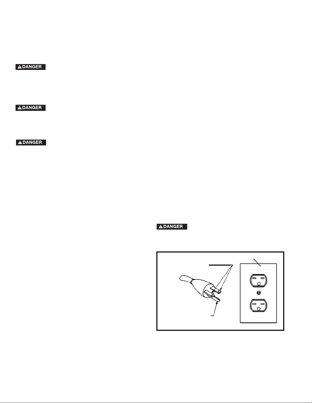
THIS MACHINE MUST BE GROUNDED WHILE IN USE TO PROTECT THE OPERATOR FROM
ELECTRIC SHOCK.
machine will have a grounding plug that looks like the
plug illustrated in Fig. A. Make sure the machine is
connected to an outlet having the same configuration as
the plug. No adapter is available or should be used with
this machine. If the machine must be re-connected for
use on a different type of electric circuit, the reconnection should be made by qualified service
personnel; and after re-connection, the machine should
comply with all local codes and ordinances.
NOTE: In Canada, the use of a temporary adapter is
not permitted by the Canadian Electric Code.
IN ALL CASES, MAKE CERTAIN THE
RECEPTACLE IN QUESTION IS
PROPERLY GROUNDED. IF YOU ARE NOT SURE HAVE
A QUALIFIED ELECTRICIAN CHECK THE RECEPTACLE.
A separate electrical circuit should be used for your machines. This circuit should not be less than #12 wire and should
be protected with a 20 Amp time lag fuse. If an extension cord is used, use only 3-wire extension cords which have 3prong grounding type plugs and matching receptacle which will accept the machine’s plug. Before connecting the
machine to the power line, make sure the switch is in the “OFF” position and be sure that the electric current is of the
same characteristics as indicated on the machine. All line connections should make good contact. Running on low
voltage will damage the machine.
DO NOT EXPOSE THE MACHINE TO RAIN OR OPERATE THE MACHINE IN DAMP LOCATIONS.
1. All grounded, cord-connected machines:
In the event of a malfunction or breakdown, grounding
provides a path of least resistance for electric current to
reduce the risk of electric shock. This machine is equipped
with an electric cord having an equipment-grounding
conductor and a grounding plug. The plug must be plugged
into a matching outlet that is properly installed and grounded
in accordance with all local codes and ordinances.
Do not modify the plug provided - if it will not fit the outlet,
have the proper outlet installed by a qualified electrician.
Improper connection of the equipment-grounding
conductor can result in risk of electric shock. The conductor
with insulation having an outer surface that is green with or
without yellow stripes is the equipment-grounding
conductor. If repair or replacement of the electric cord or
plug is necessary, do not connect the equipment-grounding
conductor to a live terminal.
Check with a qualified electrician or service personnel if the
grounding instructions are not completely understood, or if
in doubt as to whether the machine is properly grounded.
Use only 3-wire extension cords that have 3-prong
grounding type plugs and matching 3-conductor
receptacles that accept the machine’s plug. Repair or
replace damaged or worn cord immediately.
POWER CONNECTIONS
MOTOR SPECIFICATIONS
GROUNDING INSTRUCTIONS
GROUNDED OUTLET BOX
CURRENT
CARRYING
PRONGS
GROUNDING BLADE
IS LONGEST OF THE 3 BLADES
The 36-729 Unisaw has a 240 volt single phase motor rated for three horsepower and 60 HZ alternating current.
Before connecting the machine to the power source, make sure the switch is in the “OFF” position.
2. Grounded, cord-connected machines intended for
use on a supply circuit having a nominal rating
between 150 - 250 volts, inclusive:
If the machine is intended for use on a circuit that has an
outlet that looks like the one illustrated in Fig. A, the
7
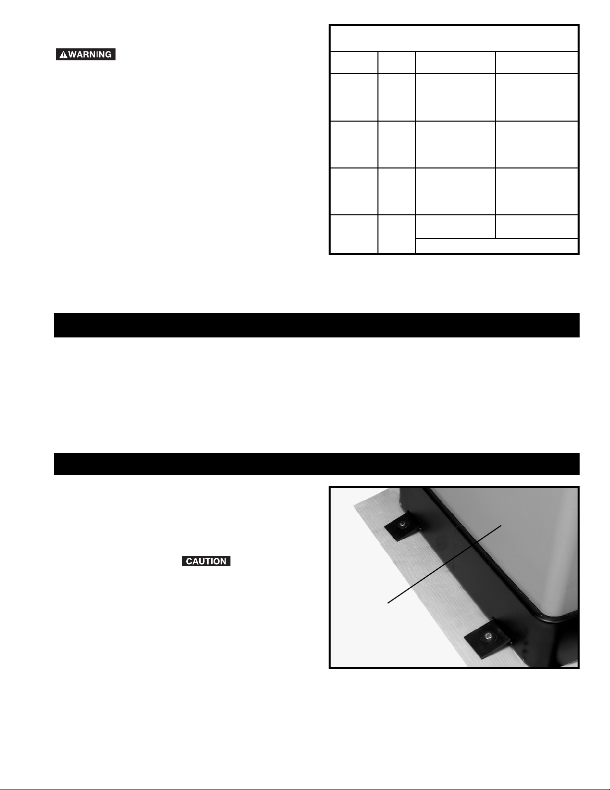
EXTENSION CORDS
Use proper extension cords. Make sure
your extension cord is in good condition and is a 3-wire
extension cord which has a 3-prong grounding type
plug and matching receptacle which will accept the
machine’s plug. When using an extension cord, be sure
to use one heavy enough to carry the current of the
machine. An undersized cord will cause a drop in line
voltage, resulting in loss of power and overheating. Fig.
D-1 shows the correct gauge to use depending on the
cord length. If in doubt, use the next heavier gauge. The
smaller the gauge number, the heavier the cord.
Fig. D-1
MINIMUM GAUGE EXTENSION CORD
RECOMMENDED SIZES FOR USE WITH STATIONARY ELECTRIC MACHINES
Ampere Total Length Gauge of
Rating Volts of Cord in Feet Extension Cord
0-6 240
up to
50 18 AWG
0-6 240 50-100 16 AWG
0-6 240 100-200 16 AWG
0-6 240 200-300 14 AWG
6-10 240
up to
50 18 AWG
6-10 240 50-100 16 AWG
6-10 240 100-200 14 AWG
6-10 240 200-300 12 AWG
10-12 240
up to
50 16 AWG
10-12 240 50-100 16 AWG
10-12 240 100-200 14 AWG
10-12 240 200-300 12 AWG
12-16 240
up to
50 14 AWG
12-16 240 50-100 12 AWG
12-16 240
GREATER THAN 100 FEET NOT RECOMMENDED
FOREWORD
Delta Model 36-729 is a 10" cabinet saw. The cabinet saw has a powerful 3 H.P. motor, and a large 36" x 27" cast-iron
table with extension wings.
FUNCTIONAL DESCRIPTION
NOTICE: THE PHOTO ON THE MANUAL COVER ILLUSTRATES THE CURRENT PRODUCTION
MODEL. ALL OTHER ILLUSTRATIONS CONTAINED IN THE MANUAL ARE REPRESENTATIVE ONLY
AND MAY NOT DEPICT THE ACTUAL COLOR, LABELING OR ACCESSORIES AND ARE INTENDED
TO ILLUSTRATE TECHNIQUE ONLY.
CARTON CONTENTS
Carefully unpack the machine and all loose items from
the shipping container(s). Remove the protective coating
from all unpainted surfaces. This coating may be removed
with a soft cloth moistened with kerosene (do not use
acetone, gasoline or lacquer thinner for this purpose). After
cleaning, cover the unpainted surfaces with a good quality
household floor paste wax. REMOVE THE
STYROFOAM PACKING AND ANY OTHER LOOSE
ITEMS FROM THE INSIDE OF THE SAW CABINET.
1. Remove the four bolts (two of which are shown) that
attach the cabinet saw (A) Fig.2, to the shipping skid.
2. Save the four bolts and the plates that mounted the
cabinet saw to the shipping skid, these bolts and plates
can be used to permanently mount the cabinet saw to a
supporting surface.
3. With two or more people slide the cabinet saw off of
the shipping skid.
Fig. 2
A
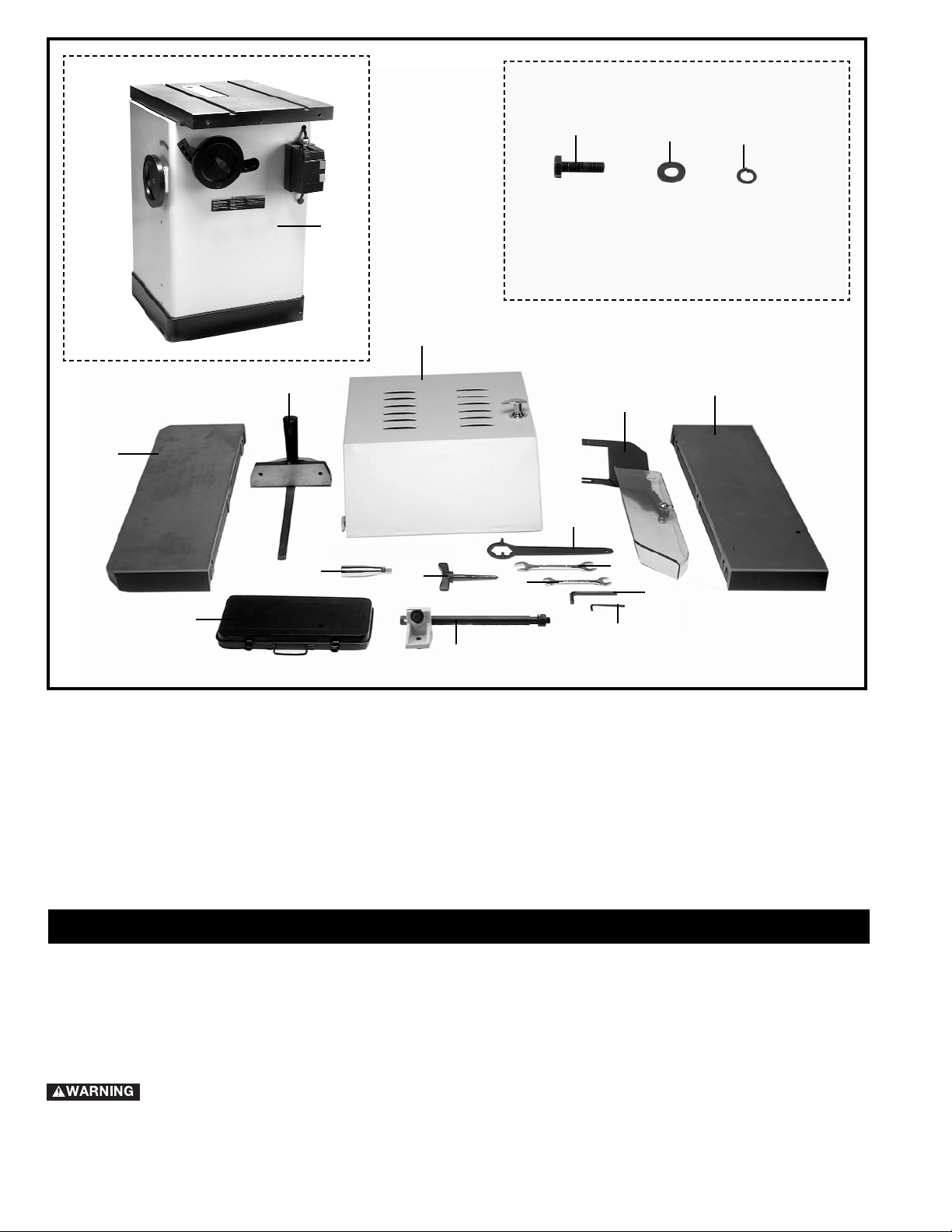
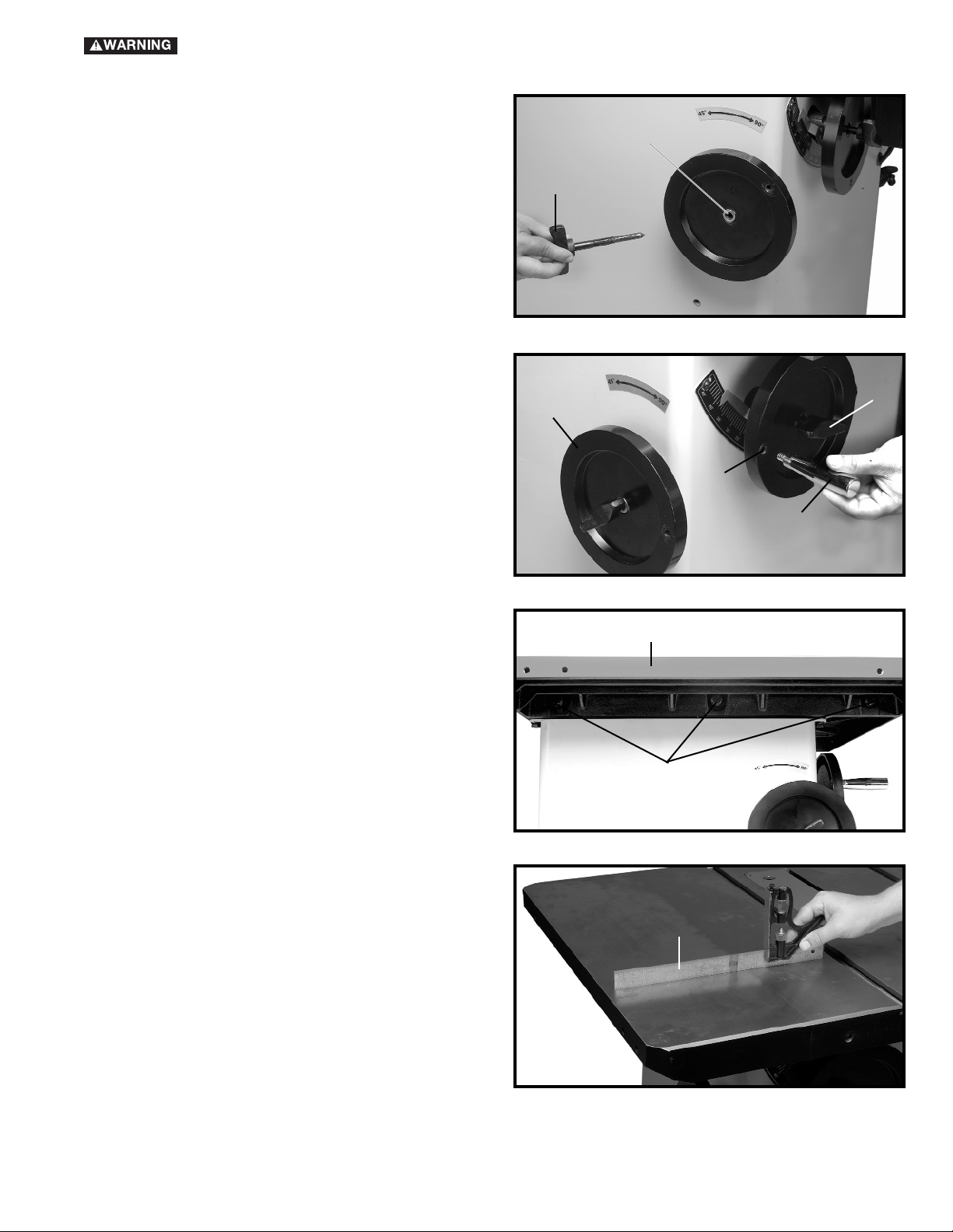
Fig. 3
1. Saw
2. M10x1.5x35mm Hex Head Bolt (6)
3. M10 Flat Washer (6)
4. M10.1 Lockwasher (6)
5. Left Side Extension Wing
6. Miter Gage
7. Motor Cover
8. Blade Guard / Splitter Assembly
9. Right Side Extension Wing
10. Tool Box
11. Handle for Operating Wheel (2)
12. Blade Tilting Lock Knob
13. Spanner Wrench
14. 19x17mm Open End Wrench
15. 14x12mm Open End Wrench
16. 8mm Hex Wrench
17. 3mm Hex Wrench
18. Support Rod / Splitter Bracket
1
2
3
4
5
6
7
8
9
10
11
12
13
14
15
16
17
18
8
ASSEMBLY
ASSEMBLY TOOLS REQUIRED
* 1/8" Hex wrench (supplied)
* 5/64" Hex wrench (supplied)
* 7/8" Open end arbor wrench (supplied)
* 7/8"x1/2" Closed end arbor wrench (supplied)
* 17 mm wrench (for extension wing assembly)
ASSEMBLY TIME ESTIMATE - 2 to 3 hrs.
FOR YOUR OWN SAFETY, DO NOT CONNECT THE MACHINE TO THE POWER SOURCE UNTIL
THE MACHINE IS COMPLETELY ASSEMBLED AND YOU READ AND UNDERSTAND THE ENTIRE
INSTRUCTION MANUAL.
9
FOR YOUR OWN SAFETY, DO NOT CONNECT THE MACHINE TO THE POWER SOURCE UNTIL
THE MACHINE IS COMPLETELY ASSEMBLED AND YOU READ AND UNDERSTAND THE ENTIRE
INSTRUCTION MANUAL.
BLADE TILTING LOCK KNOB
Thread lock knob (A) Fig. 4, into threaded end of the shaft
(B). Hand-tighten lock knob at this time.
Fig. 4
ATTACHING HANDWHEELS
1. Tighten lock knob (A) Fig. 5 on the blade height
adjusting wheel.
2. Thread handle (C) Fig. 5, into the tapped hole (D),
and tighten securely.
3. Repeat this process for attaching the handle for the
blade tilting operating wheel (E) Fig. 5.
Fig. 5
EXTENSION WINGS
Assemble the extension wing (A) Fig. 6 , to the left side of
the saw table using the three M10x1.5x35mm hex head
screws (B) and M10.1 lockwashers supplied. NOTE:
MAKE SURE FRONT EDGE OF WING IS FLUSH TO
OR SLIGHTLY BEHIND THE FRONT EDGE OF THE
TABLE. Use a straight edge (C) Fig. 7, to make sure the
extension wing (A) is level with the saw table before
tightening the screws (B) Fig. 6 with a 17mm wrench.
Assemble the right extension wing in the same manner.
Fig. 7
Fig. 6
A
B
C
D
E
A
A
B
C
 Loading...