


12" (305 mm) DOVETAIL JIG
Gabarit de queues d'aronde de 305 mm (12 po)
Guí de 305 mm (12 pulg) para cola de milano
Advanced Instruction Manual
www.deltaportercable.com/jigs
4210
4212
4216

TABLE OF CONTENTS
SAFETY GUIDELINES |
3 |
IMPORTANT SAFETY INSTRUCTIONS |
3 |
ADDITIONAL SPECIFIC SAFETY RULES |
4 |
BACKGROUND INFORMATION |
4 |
OPERATION |
5 |
MISCELLANEOUS TECHNIQUES |
5 |
THROUGH-DOVETAILS WITH CLAMPING BOARDS |
6 |
THROUGH-DOVETAILS WITH UNLIMITED BOARD WIDTH |
8 |
ALTERNATIVE METHOD - THROUGH-DOVETAILS WITH UNLIMITED BOARD WIDTH |
10 |
HALF-BLIND DOVETAILS WITH CLAMPING BOARDS |
11 |
USING A ROUTER TABLE |
13 |
ALTERNATE ROUTER BITS |
14 |
HALF-BLIND DOVETAIL TAILBOARDS THICKER THAN 7/8" |
17 |
MITERED THROUGH-DOVETAILS |
18 |
THROUGH-DOVETAIL, SKIPPED PIN METHOD |
19 |
HALF-BLIND DOVETAIL, SKIPPED PIN METHOD |
20 |
SAW KERF ALLOWANCE METHOD |
22 |
MULTIPLE SPACER METHOD |
24 |
END-TO-END JOINTS |
24 |
DRAWERS WITH SLIDING DOVETAILS |
25 |
WOODEN HINGES |
26 |
ANGLED JOINTS |
29 |
ACUTE ANGLED JOINTS |
32 |
SLANTED SIDE JOINTS |
33 |
COMPOUND ANGLED JOINTS |
34 |
INLAYED THROUGH-DOVETAILS |
37 |
INLAYED HALF-BLIND DOVETAIL JOINTS |
38 |
INLAYED BOX JOINTS |
40 |
TABLES OF COMMONLY AVAILABLE ROUTER BIT SIZES |
41 |
TROUBLESHOOTING |
42 |
MAINTENANCE |
42 |
SERVICE |
42 |
ACCESSORIES |
42 |
WARRANTY |
43 |
SERVICE CENTER LOCATIONS |
Back Cover |
2

SAFETY GUIDELINES - DEFINITIONS
This manual contains information that is important for you to know and understand. This information relates to protecting YOUR SAFETY and PREVENTING EQUIPMENT PROBLEMS. To help you recognize this information, we use the symbols to the left. Please read the manual and pay attention to these sections.
 Indicates an imminently hazardous situation which, if not avoided, will result in death or serious injury.
  Indicates a potentially hazardous situation which, if not avoided, could result in death or serious injury.
Indicates a potentially hazardous situation which, if not avoided, may result in minor or moderate injury.
Used without the safety alert symbol indicates potentially hazardous situation which, if not avoided, may result in property damage.
IMPORTANT SAFETY INSTRUCTIONS
 Read and understand all instructions. Failure to follow all instructions listed below, may result in electric shock, fire and/or serious personal injury.
SAVE THESE INSTRUCTIONS.
 There are certain applications for which this tool was designed. Porter-Cable strongly recommends that this tool NOT be modified and/or used for any application other than for which it was designed. If you have any questions relative to its application DO NOT use the tool until you have written Porter-Cable and we have advised you.
Technical Service Manager
Porter-Cable Corporation
4825 Highway 45 North Jackson, TN 38305
1.KEEP WORK AREA CLEAN. Cluttered areas and benches invite injuries.
2.AVOID DANGEROUS ENVIRONMENT. Don’t expose power tools to rain. Don’t use power tools in damp or wet locations. Keep area well lit. Avoid chemical or corrosive environment. Do not use tool in presence of flammable liquids or gases.
3.GUARD AGAINST ELECTRIC SHOCK. Prevent body contact with grounded surfaces. For example: pipes, radiators, ranges, refrigerator enclosures.
4.KEEP CHILDREN AWAY. Do not let visitors contact tool or extension cord. All visitors should be kept away from work area.
5.STORE IDLE TOOLS. When not in use, tools should be stored in dry, and high or locked-up place – out of reach of children.
6.DON’T FORCE TOOL. It will do the job better and safer at the rate for which it was intended.
7.USE RIGHT TOOL. Don’t force small tool or attachment to do the job of a heavy duty tool. Don’t use tool for purpose not intended – for example – do not use a circular saw for cutting tree limbs or logs.
8.DRESS PROPERLY. Do not wear loose clothing or jewelry. Loose clothing, draw strings and jewelry can be caught in moving parts. Rubber gloves and non-skid footwear are recommended when working outdoors. Wear protective hair covering to contain long hair.
9.USE ANSI Z87.1 SAFETY GLASSES. Wear safety glasses or goggles while operating power tools. Also face or dust mask if operation creates dust. All persons in the area where power tools are being operated should also wear safety glasses and face or dust mask.
10.DON’T ABUSE CORD. Never carry tool by cord or yank it to disconnect from receptacle. Keep cord from heat, oil, and sharp edges. Have damaged or worn power cord and strain reliever replaced immediately. DO NOT ATTEMPT TO REPAIR POWER CORD.
11.SECURE WORK. Use clamps or a vise to hold work. It’s safer than using your hand and it frees both hands to operate tool.
12.DON’T OVERREACH. Keep proper footing and balance at all times.
13.MAINTAIN TOOLS WITH CARE. Keep tools sharp and clean for better and safer performance. Follow instructions for lubricating and changing accessories. Inspect tool cords periodically and if damaged, have repaired by authorized service facility. Inspect extension cords periodically and replace if damaged. Have all worn, broken or lost parts replaced immediately. Keep handles dry, clean and free from oil and grease.
14.DISCONNECT TOOLS when not in use, before servicing, and when changing accessories such as blades, bits, cutters, etc.
15.REMOVE ADJUSTING KEYS AND WRENCHES. Form habit of checking to see that keys and adjusting wrenches are removed from the tool before turning it on.
3

16.AVOID UNINTENTIONAL STARTING. Do not carry a plugged-in tool with finger on switch. Be sure switch is off when plugging in. Keep hands, body and clothing clear of blades, bits, cutters, etc. when plugging in the tool.
17.OUTDOOR USE EXTENSION CORDS. When tool is used outdoors, use only extension cords marked “Suitable for use with outdoor appliances – store indoors when not in use.” If an extension cord is to be used outdoors it must be marked with the suffix W-A or w following the cord type designation.
18.STAY ALERT. Watch what you are doing. Use common sense. Do not operate tool when you are tired or while under the influence of medication, alcohol or drugs.
19.CHECK DAMAGED PARTS. Before further use of the tool, a guard or other part that is damaged should be carefully checked to determine that it will operate properly and perform its intended function. Check for alignment of moving parts, binding of moving parts, breakage of parts, mounting, and any other conditions that may affect its operation. A guard or other part that is damaged should be properly repaired or replaced by an authorized service center unless otherwise indicated elsewhere in this instruction manual. Have defective switches replaced by authorized service center. Do not use tool if switch does not turn it on and off.
20.WEAR ANSI S3.19 EAR PROTECTION to safeguard against possible hearing loss.
ADDITIONAL SAFETY RULES
FAILURE TO FOLLOW THESE RULES MAY RESULT IN SERIOUS PERSONAL INJURY.
1.READ AND FOLLOW ALL SAFETY INSTRUCTIONS in the instruction manual supplied with your router.
2.SECURE WORK. Be sure Dovetail Fixture/Jig and work is anchored securely to prevent movement.
3.BE SURE CORD SET IS FREE and will not hang up during routing operations.
4.KEEP HANDS CLEAR of cutter when motor is running to prevent personal injury.
5.MAINTAIN FIRM GRIP on router when starting motor to resist starting torque.
6.STAY ALERT and keep cutter free, clear of all foreign objects while motor is running.
7.BE SURE MOTOR HAS COMPLETELY STOPPED before removing router from Dovetail Fixture/Jig and setting Dovetail Fixture/Jig down between operations.
8.NEVER REMOVE ROUTER MOTOR from router base while template guide and dovetail bit are installed. dovetail bit may not fit through hole in template guide.
9.TIGHTEN TEMPLATE GUIDE LOCKNUT SECURELY.
10.SOME WOOD CONTAINS PRESERVATIVES WHICH CAN BE TOXIC. Take extra care to prevent inhalation and skin contact when working with these materials. Request, and follow, any safety information available from your material supplier.
CALIFORNIA PROPOSITION 65
Some dust created by power sanding, sawing, grinding, drilling, and other construction activities contains chemicals known to cause cancer, birth defects or other reproductive harm.
Some examples of these chemicals are:
•lead from lead-based paints,
•crystalline silica from bricks and cement and other masonry products, and
•arsenic and chromium from chemically-treated lumber.
Your risk from these exposures varies, depending on how often you do this type of work. To reduce your exposure to these chemicals: work in a well ventilated area, and work with approved safety equipment, always wear NIOSH/OSHA approved, properly fitting face mask or respirator when using such tools.
REPLACEMENT PARTS
When servicing use only identical replacement parts.
BACKGROUND INFORMATION
The details for basic joints are found in the instruction manual for the 4210, 4212 or 4216 Dovetail Jig, along with information regarding the use of various router bits and/or template guides, and will not be repeated in this supplemental manual. The purpose of this document is to provide you with an advanced knowledge of the jig and to promote that knowledge, along with your creativity, to produce beautiful woodworking projects that can stand the test of time.
4
OPERATION
MISCELLANEOUS TECHNIQUES
Using these techniques can simplify your dovetailing projects.
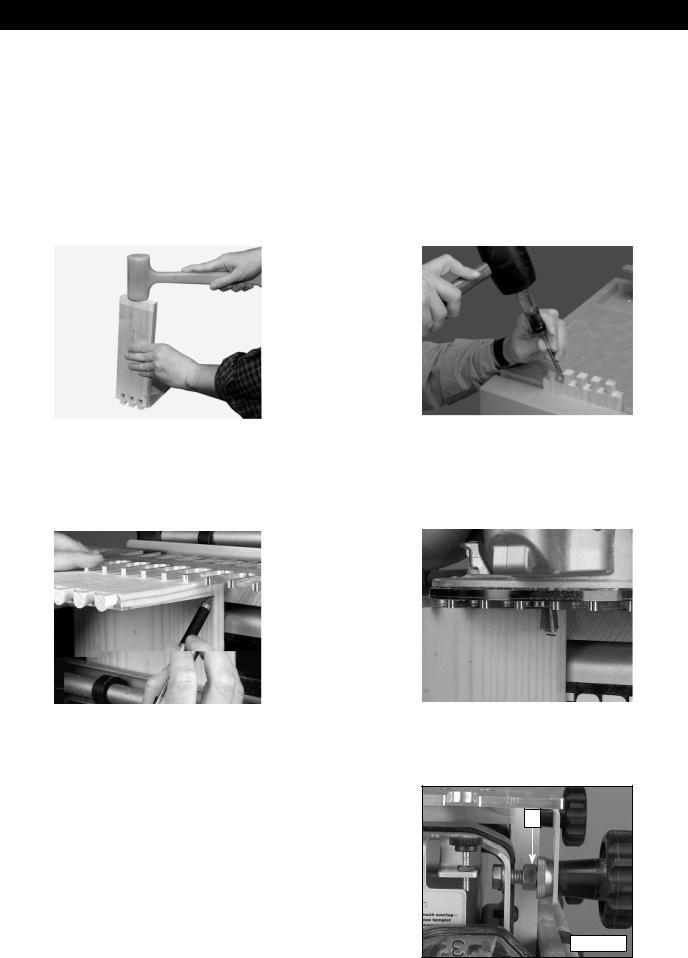
USE A DEAD-BLOW HAMMER
Use a plastic dead-blow hammer to join your workpieces together to help prevent the marring of wood (Fig. 1A).
CHAMFER THE TAIL EDGES
Chamfering the inner tail edges can make the joints go together easier and may prevent damage to the pins (Fig. 1B). Make the chamfers with a file or a chisel. Since the chamfers are located on the inside of the joint, they will be invisible.
|
|
|
|
|
|
|
|
Fig. 1A |
|
|
|
Fig. 1B |
|
|
|
|
|
|
|
|
ALTERNATE THROUGH DOVETAIL AND BOX JOINT BIT DEPTH SETTING
This method of setting your router bit depth on through dovetails or box joints is very accurate for creating pins or tails that are flush, and is especially good for inlay work. Use a board that is the same thickness as your workpiece to be joined and draw a line.
|
|
|
|
|
|
|
|
Fig. 2A |
|
|
|
Fig. 2B |
|
|
|
|
|
|
|
|
Set the router on the template and lower the router bit until it reaches the line. Make sure that the scrap material used in the horizontal position to support the template is at least as thick as the router bit depth-of-cut.
STOP NUT FOR BRASS ADJUSTMENT KNOB
If using the same setup repeatedly, you can use a 3/8"-16 nut (A) Fig. 3A (not supplied) to keep the brass adjustment knobs from moving.
A
Fig. 3A
5

TEMPLATES MOUNTED TO CLAMPING BOARDS
You can mount the jig templates to clamping boards and take the templates to the workpiece to make the joint. The benefits of this operation are:
1.You can maneuver a mounted template onto a large workpiece easier than clamping a large workpiece to the jig. This process allows you to join boards wider than 12" by routing a part of the joint, sliding the mounted template just past the original cut, and routing the remainder of the joint.
|
|
|
|
|
|
|
|
Fig. 4A |
|
|
|
Fig. 4B |
|
|
|
|
|
|
|
|
|
|
|
|
|
|
|
Fig. 4C
2.By using the clamping boards, you can rout boards that are too short to clamp in the jig base, allowing you to dovetail small decorative boxes.
3.You can make half-blind joints in thicker wood than the jig can handle.
4.You can make steeply-angled joints with the clamping boards.
5.You can make joints using a router table by inverting the mounted templates.
THROUGH-DOVETAILS WITH CLAMPING BOARDS
You can use both the normal through-dovetail template (included with the 4212 Jig and the 4213 Accessory Kit), and the miniature through-dovetail template (included with the 4215 Accessory Kit) with a clamping board.
NOTE: You can modify these clamping board methods to make box joints.
SETUP
Step 1 - Make a clamping board 2" x 3" x 19". Make sure that all four sides are square (You may need to glue thinner sections of wood together and plane them to make the 2" board).
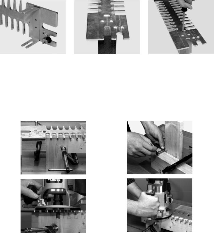
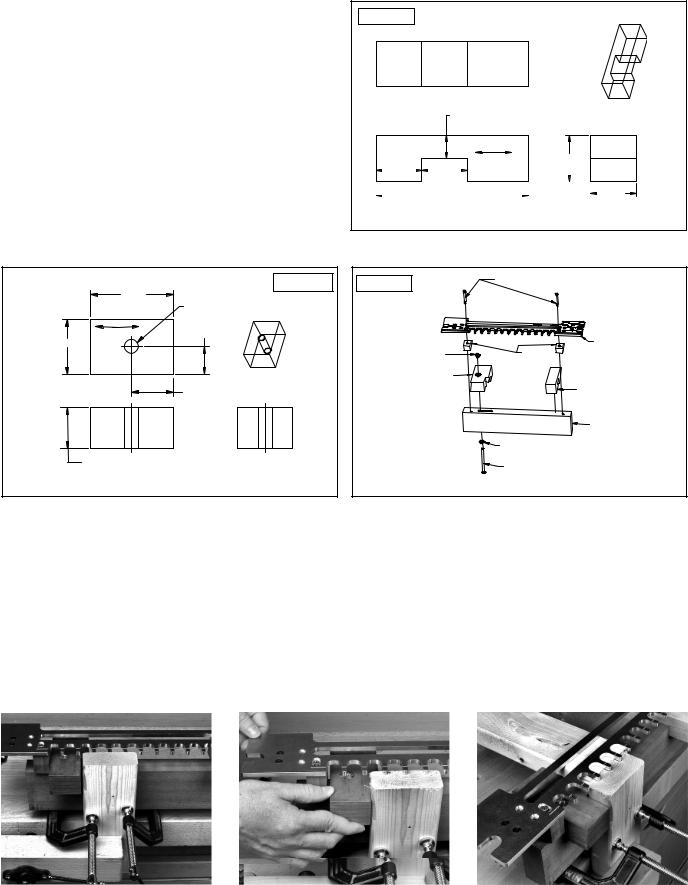
Step 2 - Drill the pilot holes for #10 screws on the face of the board as indicated in the drawing (Fig. 6A).
Step 3 - Remove the brackets from the template (Fig. 6B).
Step 4 - Align the lines of the template with the edges of the clamping board. You should be able to see the pilot holes in the elongated slot of the template Fig. 6C).
Step 5 - Drive two #10 wood screws through the elongated slots of the template into the clamping board (Fig. 6D).
DRILL PILOT HOLES |
Fig. 6A |
|
|
FOR #10 WOOD SCREWS |
1 " |
13 " |
3 " |
19 " |
|
WOOD GRAIN |
3 " |
|
|
|
2 " |
6
|
|
|
|
|
|
|
|
|
|
|
|
|
Fig. 6B |
|
|
|
|
Fig. 6C |
|
|
|
Fig. 6D |
|
|
|
|
|
|
|
|
|
|
|
|
|
CUTTING THE TAILS |
|
|
|
|
|||||||
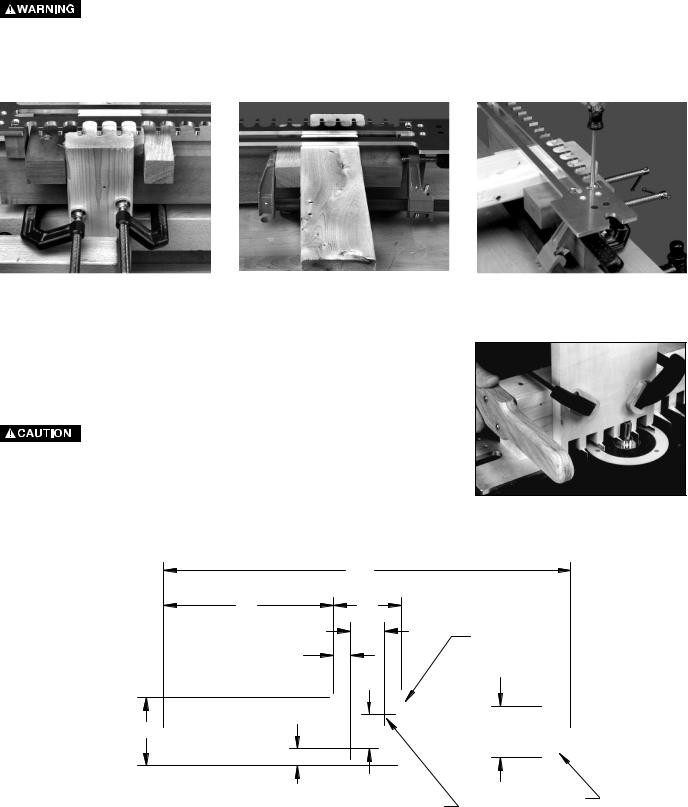
Step 1 - |
Clamp the tail board with the outside surface facing away from the clamping board (Fig. 7A). Align |
||||||||||
|
|
the tail board, using the instructions in your basic manual in the section “OPERATION”. Look under |
|||||||||
|
|
“POSITIONING THE WOOD”, STEP 4. |
|
|
|
|
|||||
Step 2 - |
This step is optional. Clamp stop blocks to the clamping board for rapid setups of repeated cuts. |
||||||||||
Step 3 - Use a small square and a pencil to draw a line along the bottom of the clamping board (Fig. 7B). Align the line with an edge of the tail board. (This line will be used to set up the pin board).
Step 4 - Use the width of the pinboard to mark the depth of the router bit on the tailboard (Fig. 7C).
 DISCONNECT THE TOOL FROM THE POWER SOURCE.
Step 5 - Set the router bit depth, using the pencil mark from STEP 4.
Step 6 - Connect your router to the power source and cut the tails (Fig. 7D).
|
|
|
|
|
|
|
|
|
|
|
Fig. 7A |
|
|
|
Fig. 7B |
|
|
|
|
|
|
|
|
|
|
|
|
|
|
|
|
|
|
|
|
|
|
|
|
|
|
|
|
|
|
|
|
|
|
|
|
|
|
|
|
|
|
|
|
|
|
|
|
|
|
|
|
|
|
|
|
7

Fig. 8A
Fig. 8C
FITTING THE JOINT
Step 1 - Orient the template so that the “PINS” side is facing you (Fig. 9A).
Step 2 - Loosen the two #10 screws.
Step 3 - If the joint is too loose, move the template toward you slightly.
Step 4 - If the joint is too tight, move the template away from you slightly.
Step 5- Tighten the screws loosened in STEP 2. Step 6 - Cut the pin board again and check for fit.
Fig. 8B
Fig. 8D
Fig. 9A
THROUGH-DOVETAILS WITH UNLIMITED BOARD WIDTH
You can cut dovetails in boards wider than the templates mounted on clamping boards by cutting the first part of the joint, sliding the template down the workpiece, and cutting the rest of the joint.
NOTE: Become familiar with the procedure for cutting through-dovetails with a template on a clamping board before attempting working with unlimited board width.
SETUP
Remove the half-blind depth bracket. Other than that, the setup is identical to the previous setup.
8
CUTTING THE TAILS
Step 1 - Clamp the tail board with the outside surface facing away from the clamping board (Fig. 10A).
Step 2 - If the board is a width in 1" increments, (12", 13", etc.), center the edge of the board exactly between the two fingers of the template farthest to the left (Fig. 10B).
Step 3 - If the board is not in 1" increments, take the fraction of an inch that is greater than 1" and divide it by two. Then move the tailboard to the left of the center of the fingers by that amount (Fig. 10C). EXAMPLE: IF the board width is 16-1/2", take the 1/2", divide it by two. You would then move the tail board to the left of the center of the fingers by 1/4" and clamp it in place.
Step 4 - Use a piece of wood the same thickness as the pin board to mark the router bit depth.
DISCONNECT THE TOOL FROM THE POWER SOURCE.
Step 5 - Set the router bit depth, using the pencil mark from STEP 4.
Step 6 - Connect your router to the power source and cut the pins as far as the template will allow.
|
|
|
|
|
|
|
|
|
|
|
|
Fig.10A |
|
|
|
Fig. 10B |
|
|
|
Fig. 10C |
|
|
|
|
|
|
|
|
|
|
|
|
Step 7 - Unclamp the template, slide it down, and center the last cut between the two straight fingers and reclamp (Fig. 10D).
Step 8 - Repeat STEPS 6 and 7 until the pins are cut across the entire board.
CUTTING THE PINS |
Fig. 10D |
Step 1 - Clamp the pin board with the outside surface facing away from the clamping board.
Step 2 - If the board is a width in 1" increments, (12", 13", etc.), center the edge of the board exactly in line with the finger of the template farthest to the left (Fig. 11A).
Step 3 - If the board is not in 1" increments, take the fraction of an inch that is greater than 1" and divide it by two. Then move the pin board to the left of center of the fingers by that amount. EXAMPLE: IF the board width is 16-1/2", take the 1/2", divide it by two. You would then move the tail board to the left of the leftmost finger by 1/4" and clamp it in place (Fig. 11B).
Step 4 - Use a piece of wood the same thickness as the pin board to mark the router bit depth.
DISCONNECT THE TOOL FROM THE POWER SOURCE.
Step 5 - Set the router bit depth, using the pencil mark from STEP 4.
Step 6 -
|
|
|
|
|
|
|
|
Fig. 11A |
|
|
|
Fig. 11B |
|
|
|
|
|
|
|
|
9
Step 7 -
Step 8 -
Step 9 -
Unclamp the template, slide it down, and center the last cut between the two angled fingers and reclamp (Fig. 11D).
Repeat STEPS 6 and 7 until the pins are cut across the entire board.
Remove the pin board and check the fit with the tailboard.
FITTING THE JOINT
Fitting the joint is identical to the previous section (Fig. 12A).
|
|
|
|
|
|
|
|
|
|
|
Fig. 11D |
|
|
|
Fig. 12A |
|
|
|
|
|
|
|
|
|
|
|
|
|
|
|
|
|
|
|
|
|
|
|
|
|
|
|
|
|
|
|
|
|
|
|
|
|
|
|
|
|
|
|
|
|
|
|
|
|
|
|
|
|
|
|
|
ALTERNATE METHOD
THROUGH-DOVETAILS WITH UNLIMITED BOARD WIDTH
This alternate method may be more accurate for correctly cutting the tail and pin boards.
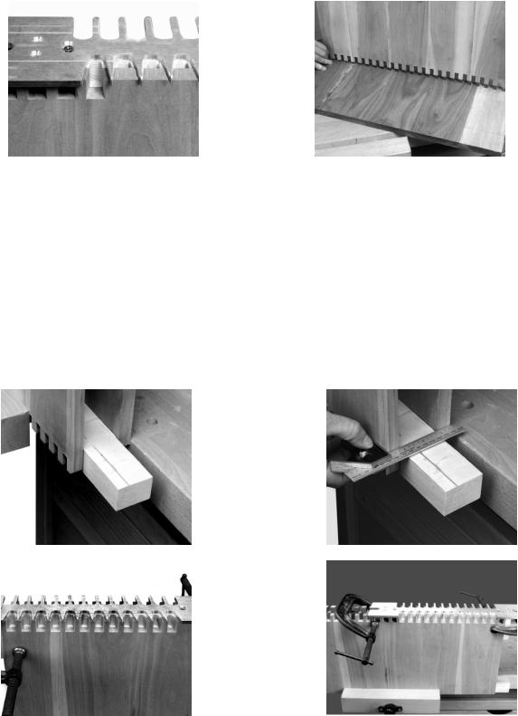
Clamp the tail and pin boards together with a 2" wide block (Fig. 13A). Step 2 - Use a square to align an edge of the tail and pin boards (Fig. 13B). Step 3 - Cut the pins and the tails as far as the template will allow (Fig. 13C).
Step 4 - Slide the template, aligning the last cut in between the fingers of the template (Fig. 13D).
Step 5 - Repeat STEPS 3 and 4 until both boards are completely cut.
|
|
|
|
|
|
|
|
Fig. 13A |
|
|
|
Fig. 13B |
|
|
|
|
|
|
|
|
|
|
|
|
|
|
|
|
Fig. 13C |
|
|
|
Fig. 13D |
|
|
|
|
|
|
|
|
|
|
|
|
|
|
|
10
HALF-BLIND DOVETAILS WITH CLAMPING BOARDS
You can mount your half-blind template that comes with the 4210 and 4212 jigs and the 4211 accessory kit to a board. This method, however, limits your workpiece width capacity to 8".
SETUP
Items needed to setup for the half-blind dovetails:
1.Wood to make the clamping board parts
2.Clamps
3.2" #10 wood screws (2)
4.1/4-20 threaded T-nut
5.1/4-20 x 4" bolt
6.1/4" washer
NOTE: These instructions can be modified for making half-blind dovetails with the through dovetail template and for the miniature dovetail template (See the section “HALF-BLIND DOVETAILS WITH TAIL BOARDS THICKER THAN 7/8").
Step 1 -
Fig. 14A
DRILL A 5/16 " HOLE
THROUGH THE BLOCK
FOR THE THREADED T-NUT
Step 2 - |
NOTE: Threaded inserts and #10 flathead machine |
|
2-1/4" |
MAKE A COUNTERBORE |
||||
|
|
|
screws can be used in place of the #10 wood |
|
|
|||
|
|
|
|
|
FOR THE THREADED |
|||
|
|
|
screws. |
|
|
|
|
T-NUT |
|
|
|
Make the offset clamping block. Make a counterbore |
|
|
|
||
|
|
|
for the threaded T-nut (Fig. 15B). |
|
|
|
||
|
|
|
NOTE: If your pin board is thinner than 3/4", modify |
|
|
1-5/8" |
||
|
|
|
the dimension. You may need to use extra washers |
|
|
|||
|
|
|
|
|
|
|||
|
|
|
to prevent the bolt from sticking out. |
|
|
|
||
|
|
|
|
|
|
1/2 " |
|
|
|
|
|
|
|
Fig. 15A |
|
|
|
2-1/4 |
" |
2 " |
3/8" WIDE MORTISE GOES |
|
1-1/2" |
|
|
|
THROUGH BLOCK. MORTISE |
|
|
|
|||||
|
|
|
|
|
|
|
3/4"(IF THE PIN BOARD IS LESS THAN 3/4" THICK, |
|
|
|
|
|
IS CENTERED ON BLOCK. |
|
|
|
|
|
|
|
|
|
|
|
|
|
|
|
|
|
|
|
|
|
THEN REDUCE THIS DIMENSION ACCORDINGLY) |
1/2 |
" |
|
|
|
|
|
|
|
1-1/8 |
" |
|
|
13-3/4 " |
DRILL PILOT HOLES |
|
|
|
|
|
FOR #10 WOOD SCREWS |
|
|
|
|||
|
|
|
|
|
|
|
WOOD GRAIN |
|
|
|
|
|
|
|
|
|
|
|
|
|
|
WOOD GRAIN |
3-1/4 " |
1-1/2" |
|
1-1/2" |
|
|
|
|
|
|
|||
16 " |
1-1/2 " |
5”
Step 3 - Insert the threaded nut into the offset clamping block (Fig. 15C).
Fig. 15C
11
Step 4 -
Step 5 -
Step 6 -
Make the straight clamping block. If the workpiece is thinner than 3/4", you will need to modify the dimension (Fig. 15D).
Make two thickness blocks the same thickness as the pin board. Drill a hole big enough for the wood screw to go through (Fig. 15E).
Assemble the board-mounted half-blind template (Fig. 15F).
NOTE: You will not need to remove the halfblind depth bracket.
Fig. 15D
3/4 " (IF THE PIN BOARD IS LESS THAN 3/4" THICK, THEN REDUCE THIS DIMENSION ACCORDINGLY)
|
|
|
|
|
|
|
|
|
WOOD GRAIN |
1-1/2 " |
|
|
|
||
|
1-1/2 " |
|
|
1-1/2 " |
|
|
|
1-1/2 " |
|||||||
|
|
|
|
|
|
|
|
|
|
|
|
||||
|
|
|
|
|
|
|
|
|
|
|
|
||||
|
|
|
|
|
5 " |
|
|
|
|
|
|
|
|
|
|
|
|
|
|
|
|
|
|
|
|
|
|
|
|
||
|
|
|
|
|
|
|
|
|
|
|
|||||
|
|
|
|
|
|
|
|
|
|
|
|
|
|
||
|
|
|
|
|
|
|
|
|
|
|
|
|
|
|
|
1-1/2 "
WOOD GRAIN
1 "
MAKE THIS DIMENSION THE THICKNESS OF THE PIN BOARD THAT IS TO BE DOVETAILED
|
Fig. 15E |
Fig. 15F |
2" LONG #10 WOOD SCREWS |
DRILL A |
1/4 " HOLE |
|
|
THROUGH THE BLOCK |
|
|
|
1/2 |
" |
|
|
|
|
|
HALF-BLIND TEMPLATE |
|
|
1/4" T-NUT |
THICKNESS |
|
|
BLOCKS |
|
|
|
|
|
|
|
OFFSET CLAMPING BLOCK |
|
3/4 " |
|
|
STRAIGHT CLAMPING BLOCK |
|
|
|
|
|
|
|
MAIN CLAMPING BOARD |
|
|
|
1/4" WASHER |
|
MAKE TWO OF THESE BLOCKS |
|
4" LONG 1/4-20 BOLT |
CUTTING THE JOINT
Step 1 -
Step 2 -
Step 3 -
Clamp the tail board (drawer side) to the main clamping board with the outside surface facing the board (Fig. 16A).
Move the offset clamping block to the right until it touches the tail board (Fig. 16B). Tighten the 1/4-20 x 4" bolt that holds the offset clamping block.
Insert the pin board (drawer front) flush against the tail board and the offset clamping block (Fig. 16C).
|
|
|
|
|
|
|
|
|
|
|
|
Fig. 16A |
|
|
|
Fig. 16B |
|
|
|
Fig. 16C |
|
|
|
|
|
|
|
|
|
|
|
|
|
|
|
|
|
|
|
|
|
|
|
12
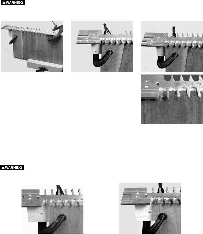
Step 4 - Slide the straight clamping block to the left so that it contacts the pin board (Fig. 16D). Hook the straight clamping block over the front and back of the main clamping board.
Step 5 - Secure the pin board by clamping it between the offset and straight clamping blocks (Fig. 16E).
Step 6 - Loosen the #10 wood screws, align the template lines with the line where the pin board and tail board meet, and retighten the #10 wood screws (Fig. 16F).
DISCONNECT THE TOOL FROM THE POWER SOURCE.
Step 7 - Set the router bit depth, using the bit depth guide.
Step 8 - Cut the joint. Fitting the joint is identical to a standard half-blind dovetail.
NOTE: You can cut the pin and tail board separately, if you prefer.
|
|
|
|
|
|
|
|
|
|
|
|
Fig. 16D |
|
|
|
Fig. 16E |
|
|
|
Fig. 16F |
|
|
|
|
|
|
|
|
||||
|
|
|
|
|
|
|
|
|
|
|
|
|
|
|
|
|
|
|
|
|
|
|
|
|
|
|
|
|
|
|
|
|
|
|
|
|
|
|
|
|
|
|
|
|
|
|
|
|
|
|
|
|
|
|
|
|
|
|
|
|
|
|
|
|
|
USING A ROUTER TABLE
You can use board-mounted templates with your router table. However, the templates must be inverted. Similarly, invert all operations (setting the router bit, etc.).
Use protective handles to keep your hands away from the router bit. Grip the handles only on the opposite side of
the workpiece.
5 " |
|
1/2 |
" |
2 " |
|
12 " |
|
|
|
2 " |
|
|
|
1 " |
RADIUS |
3/4 |
" |
|
|||
|
1-1/2 |
" |
|
1 " |
|
|
|
|
1/2 " |
ROUND OVER EDGES |
|
MAKE FROM 3/4" STOCK |
DRILL HOLES FOR SCREWS |
||
|
13
ALTERNATE ROUTER BITS
You are not limited to using the router bits supplied with your jig. Other router bits can be used to produce a different look or to work with thicker woods. Using alternate bits can help you produce more advanced joints (inlayed dovetails, etc.). Since 1/2" shank bits are stronger and are much less prone to deflection than the 1/4" shank bits, we recommend that you use the 1/2" shank bits with the 4210 and 4212 dovetail jigs, and with the 4211 and 4213 accessory kits.
THROUGH-DOVETAIL BITS
If you choose to purchase alternate through-dovetail bits, keep in mind the following:
1.The dovetail bit must have a 7° angle. This angle matches the tapered fingers used to guide the straight bit.
2.The sum of the diameters of the dovetail and straight bits must equal 15/16". For example, a 5/8" dovetail bit
must have a 5/16" straight bit - the sum of both equalling 15/16".
3.The length of the cutter determines the maximum thickness of wood that can be cut. The length of the cutter on the dovetail bit is the maximum thickness of the pin board. The length of the cutter on the straight bit is the maximum thickness of the tail board. If your bits have 1" cutters, you can make through-dovetails with 1" thick boards.
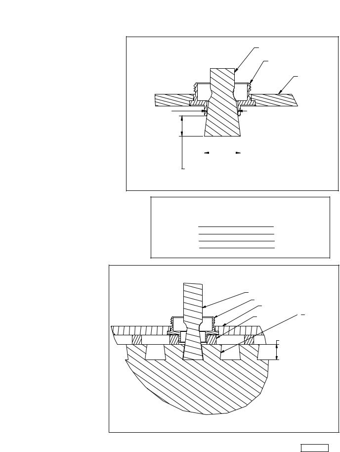
4.Purchase bits that will not cut into the template guides. The template guide used with the dovetail bit has an inside diameter of 21/32". Use bits
that will fit into this dimension. Some larger bits might work, but with minimal depth (Fig. 18A).
5.The inside diameter of the template guide used with the straight bit is 17/32". Use straight bits that are smaller than that dimension.
HALF-BLIND
DOVETAIL BITS
The difference in using alternate bits and standard bits in making half-blind dovetails is in the depth-of-cut.
DOVETAIL BIT
TEMPLET GUIDE
ROUTER SUB BASE
21/32"
|
|
|
DOVETAIL BIT DIAMETER |
|
|
|
|
|
|
||
THERE IS A MINIMUM DEPTH OF CUT |
|
||||
WHEN THE DIAMETER OF THE ROUTER |
|
||||
BIT IS GREATER THAN THE INSIDE |
|
||||
Fig. 18A |
|||||
DIAMETER OF THE TEMPLET GUIDE |
|||||
THROUGH-DOVETAIL BIT
COMBINATIONS (READILY AVAILABLE)
3/4" |
3/16" |
5/8" |
5/16" |
9/16" |
3/8" |
17/32" |
13/32" |
|
DOVETAIL BIT |
|
TEMPLET GUIDE |
|
ROUTER SUB BASE |
|
WOOD FOR HALF-BLIND JOINT |
|
HALF-BLIND TEMPLET |
|
DEPTH OF CUT FOR A HALF-BLIND JOINT |
Fig. 19A
14
 Loading...