


|
|
ESPAÑOL: PÁGINA 21 |
|
|
FRANÇAISE : PAGE 41 |
Instruction |
12" Compound |
|
Manual |
|
Miter Saw |
To learn more about Porter-Cable visit our website at:
http://www.porter-cable.com
Copyright © 2000 PORTER-CABLE Corporation
IMPORTANT
Please make certain that the person who is to use this equipment carefully reads and understands these instructions before starting operations.
The Model and Serial No. plate is located on the main housing of the tool. Record these numbers in the spaces below and retain for future reference.
Model No. _____________________________________
Type __________________________________________
Serial No.______________________________________
Part No. 900988 - 11-30-00
IMPORTANT SAFETY INSTRUCTIONS
SAVE THESE INSTRUCTIONS
READ AND FOLLOW ALL INSTRUCTIONS.
This tool was designed for certain applications.DO NOT modify or use it for any application other than for which it was designed. If you have any questions relative to its application do not use the tool until you have written Porter-Cable and we have advised you.
Technical Service Manager
Porter-Cable Corporation
4825 Highway 45 North Jackson, TN 38305
WARNING: FAILURE TO FOLLOW THESE RULES
MAY RESULT IN SERIOUS PERSONAL INJURY.
1.FOR YOUR OWN SAFETY, READ INSTRUCTION MANUAL BEFORE OPERATING THE TOOL. Learn the tool’s application and limitations as well as the specific hazards peculiar to it.
2.KEEP GUARDS IN PLACE and in working order.
3.GROUND ALL TOOLS. If tool is equipped with three-prong plug, it should be plugged into a three-hole electrical receptacle. If an adapter is used to accommodate a two-prong receptacle, the adapter lug must be attached to a known ground. Never remove the third prong.
4.REMOVE ADJUSTING KEYS AND WRENCHES. Form habit of checking to see that keys and adjusting wrenches are removed from the tool before turning it on.
5.KEEP WORK AREA CLEAN. Cluttered areas and benches invite accidents.
6.DON’T USE IN DANGEROUS ENVIRONMENT. Don’t use power tools in damp or wet locations, or expose them to rain. Keep work area well-lighted.
7.KEEP CHILDREN AND VISITORS AWAY. All children and visitors should be kept a safe distance from work area.
8.MAKE WORKSHOP CHILDPROOF – with padlocks, master switches, or by removing starter keys.
9.DON’T FORCE TOOL. It will do the job better and be safer at the rate for which it was designed.
10.USE RIGHT TOOL. Don’t force tool or attachment to do a job for which it was not designed.
11.WEAR PROPER APPAREL. No loose clothing, gloves, neckties, rings, bracelets, or other jewelry to get caught in moving parts. Nonslip footwear is recommended. Wear protective hair covering to contain long hair.
12.ALWAYS USE SAFETY GLASSES. Wear safety glasses (must comply with ANSI Z87.1). Everyday eyeglasses only have impact resistant lenses; they are not safety glasses. Also use face or dust mask if cutting operation is dusty.
13.SECURE WORK. Use clamps or a vise to hold work when practical.
14.DON’T OVERREACH. Keep proper footing and balance at all times.
15.MAINTAIN TOOLS IN TOP CONDITION. Keep tools sharp and clean for best and safest performance. Follow instructions for lubricating and changing accessories.
16.DISCONNECT TOOLS before servicing and when changing accessories such as blades, bits, cutters, etc.
17.USE RECOMMENDED ACCESSORIES. The use of improper accessories may cause hazards or risk of injury to persons.
18.REDUCE THE RISK OF UNINTENTIONAL STARTING. Make sure switch is in “OFF” position before plugging in power cord.
19.NEVER STAND ON TOOL. Serious injury could occur if the tool is tipped or if the cutting tool is accidentally contacted.
20.CHECK DAMAGED PARTS. Before further use of the tool, a guard or other part that is damaged should be carefully checked to determine that it will operate properly and perform its intended function. Check for alignment of moving parts, binding of moving parts, breakage of parts, mounting, and any other conditions that may affect its operation. A guard or other part that is damaged should be properly repaired or replaced by an authorized service center unless otherwise indicated elsewhere in this instruction manual. Have defective switches replaced by authorized service center. Do not use tool if switch does not turn it on and off.
21.DIRECTION OF FEED. Feed work into a blade or cutter against the direction of rotation of the blade or cutter only.
22.NEVER LEAVE TOOL RUNNING UNATTENDED. TURN POWER OFF. Don’t leave tool until it comes to a complete stop.
23.DRUGS, ALCOHOL, MEDICATION. Do not operate tool while under the influence of drugs, alcohol or any medication.
24.MAKE SURE TOOL IS DISCONNECTED FROM POWER SUPPLY while motor is being mounted, connected or reconnected.
2
25. WARNING: SOME DUST CREATED BY POWER SANDING, SAWING, GRINDING, DRILLING, AND OTHER CONSTRUCTION ACTIVITIES contains chemicals known to cause cancer, birth defects or other reproductive harm. Some examples of these chemicals are:
•lead from lead-based paints,
•crystalline silica from bricks and cement and other masonry products, and •arsenic and chromium from chemically-treated lumber.
Your risk from these exposures varies, depending on how often you do this type of work. To reduce your exposure to these chemicals: work in a well ventilated area, and work with approved safety equipment, such as those dust masks that are specially designed to filter out microscopic particles.
SAVE THESE INSTRUCTIONS. Refer to them often and use them to instruct others.
ADDITIONAL SAFETY RULES FOR COMPOUND MITER SAWS
1.WARNING: USE ONLY CROSS-CUTTING SAW BLADES. DO NOT USE BLADES WITH DEEP GULLETS AS THEY CAN DEFLECT AND CONTACT THE GUARD.
2.WARNING: Do not operate the miter saw until it is completely assembled and installed according to the instructions.
3.IF YOU ARE NOT thoroughly familiar with the operation of compound miter saws, obtain advice from your supervisor, instructor or other qualified person.
4.BE SURE blade is sharp, runs freely and is free of vibration.
5.ALLOW the motor to come up to full speed before starting cut.
6.KEEP motor air slots clean and free of chips.
7.ALWAYS MAKE SURE rotating table is tight before cutting, even if the table is positioned in one of the positive stops.
8.BE SURE blade and flanges are clean and that arbor screw is tightened securely.
9.USE ONLY blade flanges specified for your saw.
10.NEVER apply lubricants to the blade when it is running.
11.ALWAYS CHECK the blade for cracks or damage before operation. Replace cracked or damaged blade immediately.
12.ALWAYS KEEP the lower blade guard in place and operating properly.
13.MAKE SURE blade is not contacting workpiece before switch is turned on.
14.NEVER LOCK the switch in the “ON” position.
15.IMPORTANT: After completing cut, release power switch and wait for coasting blade to stop before returning saw to raised position.
16.DO NOT remove jammed or cut-off pieces until blade has stopped.
17.NEVER cut ferrous metals or masonry.
18.NEVER recut small pieces.
19.PROVIDE ADEQUATE SUPPORT to the sides of the saw table for long workpieces.
20.NEVER use the miter saw in an area with flammable liquids or gases.
21.NEVER USE SOLVENTS TO CLEAN PLASTIC PARTS. Solvents could possibly dissolve or otherwise damage the material. Only a soft, damp cloth should be used to clean plastic parts.
22.DISCONNECT SAW from power source and clean the machine before leaving it.
23.MAKE SURE the work area is cleaned before leaving the machine.
24.ADDITIONAL INFORMATION regarding the safe and proper operation of this product is available from the National Safety Council, 1121 Spring Lake Drive, Itasca, IL 60143-3201, in the Accident Prevention Manual for Industrial Operation and also in the Safety Data Sheets provided by the NSC. Please also refer to the American National Standard Institute ANSI 01.1 Safety Requirements for the Woodworking Machinery and the U.S. Department of Labor OSHA 1910.213 Regulations.
25.SOME WOOD CONTAINS PRESERVATIVES WHICH CAN BE TOXIC. Take extra care to prevent inhalation and skin contact when working with these materials. Request, and follow, any safety information available from your material supplier.
26.DON’T ABUSE CORD. Never carry tool by cord or yank it to disconnect from receptacle. Keep cord from heat, oil, and sharp edges. Have damaged or worn power cord and strain reliever replaced immediately. DO NOT
ATTEMPT TO REPAIR POWER CORD.
27.WEAR EAR PROTECTION to safeguard against possible hearing loss.
28.AVOID CUTTING NAILS AND KNOTS. Inspect for and remove all nails from lumber before cutting. Try to do layout cuts between knots.
29.NEVER USE LIQUID COOLANT. To do so could present electrical shock hazard.
30.KEEP CLEAR OF SAWDUST EJECTION CHUTE. Sawdust and chips are expelled out the ejection chute at rear of saw. Do not allow anyone in this area while saw is in operation.
31.WHEN THE MITER SAW IS NOT IN USE, the switch should be locked in the OFF position to prevent unauthorized use of the saw.
3
REPLACEMENT PARTS
When servicing, use only identical replacement parts.
POLARIZED PLUGS: To reduce the risk of electric shock, this equipment has a polarized plug (one blade is wider than the other). This plug will fit in a polarized outlet only one way. If the plug does not fit fully in the outlet, reverse the plug. If it still does not fit, contact a qualified electrician to install the proper outlet. Do not change the plug in any way.
MOTOR
Many Porter-Cable tools will operate on either D.C., or single phase 25 to 60 cycle A.C. current and voltage within plus or minus 5 percent of that shown on the specification plate of the tool. Several models, however, are designed for A.C. current only. Refer to the specification plate on your tool for proper voltage and current rating.
CAUTION: Do not operate your tool on a current where the voltage is not within correct limits. Do not operate tools rated A.C. on a D.C. current. To do so may seriously damage the tool.
RECOMMENDED EXTENSION CORD SIZES FOR
USE WITH STATIONARY ELECTRIC TOOLS
|
MINIMUM GAUGE EXTENSION CORD |
|||
EXTENSION CORD SELECTION |
RECOMMENDED SIZES FOR USE WITH STATIONARY ELECTRIC TOOLS |
|||
Ampere |
Volts |
Total Length of |
Gauge of |
|
|
Rating |
|
Cord in Feet |
Extension Cord |
Use proper extension cords. Make sure your |
0-6 |
120 |
up to 25 |
18 AWG |
extension cord is in good condition. When |
0-6 |
120 |
25-50 |
16 AWG |
using an extension cord, be sure to use one |
0-6 |
120 |
50-100 |
16 AWG |
heavy enough to carry the current of the saw. |
0-6 |
120 |
100-150 |
14 AWG |
An undersized cord will cause a drop in line |
6-10 |
120 |
up to 25 |
18 AWG |
voltage, resulting in loss of power and |
6-10 |
120 |
25-50 |
16 AWG |
overheating. Fig. 1, shows the correct gauge to |
6-10 |
120 |
50-100 |
14 AWG |
use depending on the cord length. If in doubt, |
6-10 |
120 |
100-150 |
12 AWG |
use the next heavier gauge. The smaller the |
10-12 |
120 |
up to 25 |
16 AWG |
gauge number, the heavier the cord. |
10-12 |
120 |
25-50 |
16 AWG |
|
10-12 |
120 |
50-100 |
14 AWG |
|
10-12 |
120 |
100-150 |
12 AWG |
|
12-16 |
120 |
up to 25 |
14 AWG |
|
12-16 |
120 |
25-50 |
12 AWG |
|
12-16 |
120 |
GREATER THAN 50 FEET NOT RECOMMENDED |
|
|
|
|
|
|
Fig. 1
OPERATING INSTRUCTIONS
FOREWORD
Porter-Cable Model 3802 Type 2 is a high capacity 12" compound miter saw designed to cut wood and nonferrous metals. It can crosscut 8" x 2¼" and 7" x 3¼", miter at 45 both left and right 5¼" x 2¼", bevel at 45 left 6¼" x 2¼" and 8" x 1¼", and compound 45 x 45, 5¼" x 2 1/2" and 4¼" x 2¼". It has positive miter stops at 0, 15, 22.5, 31.62, and 45 degrees both left and right, and bevel stops at 0 and 45 degrees left.
POWER CONNECTIONS
A separate electrical circuit should be used for your tools. If an extension cord is used, make sure the conductor size is large enough to prevent excessive voltage drop which will cause loss of power and possible motor damage. For distances up to 100 feet, use #12 wire. For distances up to 150 feet, use #10 wire. If an extension cord is to be used outdoors, it must be marked with the suffix W-A following the cord type designation. For example – SJTW-A indicates that it is acceptable for outdoor use. Replace damaged or worn cords immediately. Before connecting the motor to the power line, make sure the switch is in the “OFF” position and be sure that the electric current is of the same characteristics as stamped on motor nameplate.
4
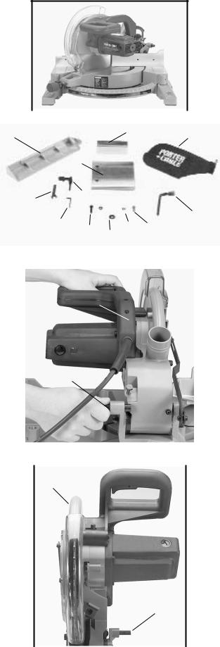
UNPACKING
1. Carefully remove the machine from the carton. Retain all packing materials until you have inspected and satisfactorily operated the machine.
WARNING: Do not connect the machine to the power source until you have read and understood this entire instruction manual.
2. Place the machine on a firm, level surface with extra room for handling and proper support of the workpiece.
3. Familiarize yourself with all features and controls as |
|
|
|
|
|
|
|
|
|
||
|
|
|
|
|
|
|
|
|
|||
|
|
|
|
Fig. 2 |
|
|
|
|
|||
explained in this manual. |
|
|
|
|
|
|
|
|
|
||
|
|
|
|
|
|
|
|
|
|
||
|
|
2 |
|
|
|
|
3 |
4 |
|
||
|
|
|
1 |
|
|
|
|
|
|||
4. The machine is shipped with the cuttinghead locked |
|
|
|
|
|
|
|
|
|
|
|
in the down position and the table rotated to 45 degrees |
|
8 |
|
|
|
|
|
||||
left, Fig. 2. To release the head and move it to the |
|
|
|
|
|
|
|||||
|
7 |
|
|
|
|
|
|||||
operating position, see “MOVING CUTTINGHEAD TO |
|
|
|
|
|
|
5 |
||||
THE UP POSITION” and “MOVING THE TABLE TO |
|
6 |
|
||||||||
|
10 |
|
|
|
|
||||||
THE 90 DEGREE CUT-OFF POSITION” in this section. |
|
12 |
|
|
|
||||||
|
11 |
|
|
|
|||||||
|
|
|
|
|
|
|
9 |
|
|
|
|
|
|
|
|
|
|
|
|
|
|
|
|
|
|
|
|
|
|
|
Fig. 3 |
|
|
|
|
5. Unassembled items are shown in Fig. 3 for |
|
|
|
|
|
|
|
|
|
||
|
|
|
|
|
|
|
|
|
|||
identification and use in assembling the saw. |
|
|
|
B |
|
|
|
|
|
||
1 |
Extension table |
|
|
|
|
|
|
|
|
||
|
|
|
|
|
|
|
|
|
|||
2 |
Fence slide |
|
|
|
|
|
|
|
|
|
|
3 |
Fence slide support |
|
|
|
|
|
|
|
|
|
|
4 |
Dust bag |
|
|
|
|
|
|
|
|
|
|
5 |
Arbor and fence wrench |
|
|
|
|
|
|
|
|
|
|
6 |
¼" wrench |
|
|
|
|
|
|
|
|
|
|
7 |
Open end wrench |
|
|
|
|
|
|
|
|
|
|
8 |
Lock handle for slide fence |
|
|
|
A |
|
|
|
|
|
|
9 |
¼" flat washer |
|
|
|
|
|
|
|
|
||
|
|
|
|
|
|
|
|
|
|||
10 |
¼" lock washer |
|
|
|
|
|
|
|
|
|
|
11 |
¼ - 18 x 1 1/4" long hex head screw (2) |
|
|
|
|
|
|
|
|
|
|
12 |
¼ - 18 x 3/4" long hex head screws (2) |
|
|
|
|
|
|
|
|
|
|
|
|
|
|
|
|
|
|
|
|
|
|
|
|
|
|
|
|
|
Fig. 4 |
|
|
|
|
|
ASSEMBLY |
|
|
|
|
|
|
|
|
|
|
|
|
|
|
B |
|
|
|
|
|
||
|
|
|
|
|
|
|
|
|
|
|
|
WARNING: FOR YOUR OWN SAFETY, DO NOT
CONNECT THE MITER SAW TO THE POWER
SOURCE UNTIL THE MACHINE IS COMPLETELY
ASSEMBLED AND YOU HAVE READ AND
UNDERSTOOD THE ENTIRE OWNER’S MANUAL.
MOVING CUTTINGHEAD TO THE UP
POSITION
1. |
Pull out cuttinghead lockpin (A) Fig. 4, and move the |
|
cuttinghead (B) to the up position. |
|
|
2. |
Fig. 5, illustrates the lockpin (A) pulled out and the |
A |
cuttinghead (B) in the up position. |
|
|
|
|
|
|
|
Fig. 5 |
5
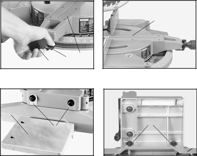
MOVING TABLE TO THE 0 DEGREE CUT-OFF POSITION
1.Rotate locking knob (A) Fig. 6, counter-clockwise as far as it will go to unlock. Depress lever (B) and rotate table (C) to the 0 degree straight cut-off position, release lever (B) and tighten locking knob (A).
2.Fig. 7, illustrates the table (C) in the 0 degree straight cut-off position.
3.For proper operation and adjustment of the table, refer to sections, “ROTATING TABLE FOR MITER CUTTING”, “ADJUSTING CLAMPING ACTION OF TABLE LOCKING MECHANISM” and “ADJUSTING
SLIDING FIT BETWEEN MOVABLE TABLE AND BASE.”
ATTACHING EXTENSION TABLE AND FENCE SLIDE
C
B
A
Fig. 6
B
A
Fig. 7A
C
Fig. 7
B 
C
Fig. 7B
1. Attach flat washers to the two 3/4” screw assemblies (A) Fig. 7A, and thread into the threaded holes on left side of the saw.
NOTE: Turn the screws only a few threads into the holes at this time.
2. Attach the table extension (B) Figs. 7A and 7B, to left side of saw table, making sure groove of table extension (B) is inside flat washers (C) as shown in Fig. 7B.
6

E
H
C D
G
 F
F 
B
B
Fig. 7C |
Fig. 7D |
|
3.Use a straight edge (C) Fig. 7C, to make the extension table (B) even with saw table (D), and tighten the two screws (A) Fig. 7B.
4.Attach the fence slide support (E) Fig. 7D, to the extension table (B) by using the two 1 1/4” long hex head screws, 5/16” lockwashers and 5/16” flat washers (F). Bring screws up through the two holes (G) in table extension and thread them into the two threaded holes (H) on bottom of fence slide support.
NOTE: Do not completely tighten screws at this time.
E J
J
C |
|
|
|||
|
|
|
K |
E |
|
|
|
|
|
|
|
Fig. 7E |
|
|
|
||
|
Fig. 7F |
|
|||
|
|
|
|
|
|
5.Use a straight edge (C) Fig. 7E, to level the fence slide support (E) with saw fence (J), and tighten the two
6.Position the fence slide (K) Fig. 7F, in position on top of saw fence (J) and fence slide support (E). Slide fence slide (K) back and forth several times to check alignment of fence slide support (E). Make any necessary final adjustments to fence slide support.
M |
L |
N |
|
N
O
E
Fig. 7G |
Fig. 7H |
7.Remove screw and spring (L) Fig. 7G, and lock handle (M) from locking stud (N).
8.PLace 1/4" flat washer (O) Fig. 7G, onto locking stud (N) and insert locking stud (N) Fig. 7H, through slot in fence slide. Thread locking stud into threaded hole in fence slide support (E).
7
 Loading...