

Porter-Cable 343, 343VS, 344, 353 Instruction Manual
before making any adjustments, changing accessories, or storing power tools. Such
preventive safety measures reduce the risk of starting the power tool accidentally.
d) Store idle power tools out of the reach of children and do not allow persons unfamiliar
with the power tool or these instructions to operate the power tool. Power tools are dan-
gerous in the hands of untrained users.
e) Maintain power tools. Check for misalignment or binding of moving parts, breakage of
parts and any other condition that may affect the power tool’s operation. If damaged,
have the power tool repaired before use. Many accidents are caused by poorly maintained
power tools.
f) Keep cutting tools sharp and clean. Properly maintained cutting tools with sharp cutting
edges are less likely to bind and are easier to control.
g) Use the power tool, accessories and tool bits etc., in accordance with these instructions
taking into account the working conditions and the work to be performed. Use of the
power tool for operations different from those intended could result in a hazardous situation.
5) SERVICE
a) Have your power tool serviced by a qualified repair person using only identical replace-
ment parts. This will ensure that the safety of the power tool is maintained.
ADDITIONAL SPECIFIC SAFETY RULES
• Hold power tools by insulated gripping surfaces when performing an operation where the cutting tool may contact hidden wiring or its own cord. Contact with a “live” wire will make exposed
metal parts of the tool “live” and shock the operator.
• Do not sand metal of any kind with your sander. Sparks may be generated by sanding screws,
nails or other metals which may ignite dust particles.
• Do not wet sand with this sander. Liquids may enter the motor housing and cause electric
shock.
• Empty dust collection system frequently, especially when sanding resin-coated surfaces
such as polyurethane, varnish, shellac, etc. Dispose of coated dust particles according to
the finish manufacturer’s guidelines, or place in a metal can with a tight fitting metal lid. Remove
coated dust particles from the premises daily. The accumulation of fine sanding dust particles
may self ignite and cause fire.
• Do not operate this tool for long periods of time. Vibration caused by the operating action of this
tool may cause permanent injury to fingers, hands, and arms. Use gloves to provide extra cushion,
take frequent rest periods, and limit daily time of use.
• Sanding of lead-based paint, chemically pressure treated lumber or other materials that may
contain carcinogens is not recommended. Sanding of these materials should only be performed
by a professional.
• Clean out your tool often, especially after heavy use. Dust and grit containing metal particles
often accumulate on interior surfaces and could create a risk of serious injury, electric shock or electrocution. ALWAYS disconnect the sander from the power source before cleaning. ALWAYS WEAR
SAFETY GLASSES that conform to ANSI Z87.1.
• ALWAYS disconnect tool from the power source before changing abrasive belts or sheets.
Such preventive safety measures reduce the risk of starting the power tool accidentally.
• Do not use PSA pads on random orbit sanders whose speed exceeds 12,000/min. The PSA
pad may rupture or fly apart during use causing serious personal injury to the user and bystanders.
EXTENSION CORD
An extension cord must have adequate wire size (AWG or American Wire Gauge) for safety.
The smaller the gauge number of the wire, the greater the capacity of the cable, that is 16 gauge
has more capacity than 18 gauge. An undersized cord will cause a drop in line voltage resulting in
loss of power and overheating. When using more than one extension to make up the total length, be
sure each individual extension contains at least the minimum wire size. The following table shows
the correct size to use depending on cord length and nameplate ampere rating. If in doubt, use the
next heavier gauge. The smaller the gauge number, the heavier the cord.
Minimum Gauge for Cord Sets
Ampere Rating
Volts Total Length of Cord in Feet (meters)
120V
25 (7.6) 50 (15.2) 100 (30.5) 150 (45.7)
240V
50 (15.2) 100 (30.5) 200 (61.0) 300 (91.4)
More
Than
Not More
Than
AWG
0 6 18 16 16 14
6 10 18 16 14 12
10 12 16 16 14 12
12 16 14 12 Not Recommended
Some dust created by power sanding, sawing, grinding, drilling, and other construction activities contains chemicals known to the State of California to cause cancer, birth defects or other reproductive
harm. Some examples of these chemicals are:
• lead from lead-based paint.
• crystalline silica from bricks and cement and other masonry products.
• arsenic and chromium from chemically-treated lumber (CCA).
Your risk from exposure to these chemicals varies, depending on how often you do this type of work. To
reduce your exposure to these chemicals: work in a well ventilated area with approved safety equipment,
such as dust masks that are specially designed to filter out microscopic particles.
Avoid prolonged contact with dust from power sanding, sawing, grinding, drilling, and other
construction activities. Wear protective clothing and wash exposed areas with soap and water. Allowing
dust to get into your mouth, eyes, or lay on the skin may promote absorption of harmful chemicals.
Use of this tool can generate and/or disburse dust, which may cause serious and permanent respiratory damage or other injury. Always use NIOSH/OSHA/MSHA approved respiratory protection
appropriate for the dust exposure. Direct particles away from face and body.
ALWAYS wear proper personal hearing protection that conforms to ANSI S12.6 (S3.19) during use. Under some conditions and duration of use, noise from this product may contribute to hearing
loss.
ALWAYS USE SAFETY GLASSES. (ANSI Z87.1) and (CAN/CSA Z94.3) Everyday eyeglasses are NOT safety glasses. Also use face or dust mask if cutting operation is dusty. ALWAYS WEAR
CERTIFIED SAFETY EQUIPMENT:
• ANSI Z87.1 eye protection (CAN/CSA Z94.3)
• ANSI S12.6 (S3.19) hearing protection
• NIOSH/OSHA/MSHA respiratory protection
SYMBOLS
The label on your tool may include the following symbols.
The symbols and their definitions are as
follows:
V .......................volts A .................amperes
Hz .................... hertz W ................watts
min ................... minutes ..............alternating current
................direct current ..............alternating or direct current
.....................Class I Construction
n
o ............... no load speed
......................... (grounded) ...............earthing terminal
....................Class II Construction ...............safety alert symbol
......................... (double insulated) BPM ...........beats per minute
…/min .............. per minute RPM ........... revolutions per minute
OPM ................ orbits per minute
ADDITIONAL SAFETY RULES FOR PAINT REMOVAL
1. Sanding of lead based paint is NOT RECOMMENDED due to the difficulty of controlling the contaminated dust. The greatest danger of lead poisoning is to children and pregnant women.
2. Since it is difficult to identify whether or not a paint contains lead without a chemical analysis, we
recommend the following precautions when sanding any paint:
PERSONAL SAFETY
1. No children or pregnant women should enter the work area where the paint sanding is being
done until all clean up is completed.
2. A dust mask or respirator should be worn by all persons entering the work area. The filter should
be replaced daily or whenever the wearer has difficulty breathing. See your local hardware store
for the proper NIOSH approved dust mask.
3. NO EATING, DRINKING or SMOKING should be done in the work area to prevent ingesting
contaminated paint particles. Workers should wash and clean up BEFORE eating, drinking or
smoking. Articles of food, drink, or smoking should not be left in the work area where dust would
settle on them.
ENVIRONMENTAL SAFETY
1. Paint should be removed in such a manner as to minimize the amount of dust generated.
2. Areas where paint removal is occurring should be sealed with plastic sheeting of 4 mil thickness.
3. Sanding should be done in a manner to reduce tracking of paint dust outside the work area.
CLEANING AND DISPOSAL
1. All surfaces in the work area should be vacuumed and thoroughly cleaned daily for the duration
of the sanding project. Vacuum filter bags should be changed frequently.
2. Plastic drop cloths should be gathered up and disposed of along with any dust chips or other
removal debris. They should be placed in sealed refuse receptacles and disposed of through
regular trash pick-up procedures. During clean up, children and pregnant women should be kept
away from the immediate work area.
3. All toys, washable furniture and utensils used by children should be washed thoroughly before
being used again.
Save theSe inStructionS
MOTOR
Be sure your power supply agrees with nameplate marking. 120 Volts AC means your tool will operate on
alternating or direct current. As little as 10% lower voltage can cause loss of power and can result in overheating. All Porter Cable tools are factory-tested; if this tool does not operate, check the power supply.
Accessories must be rated for at least the speed recommended on the tool warning label.
Accessories running over rated speed can fly apart and cause injury. Accessory ratings must always be
above tool speed as shown on tool nameplate.
DEFINITIONS - SAFETY GUIDELINES
indicates an imminently hazardous situation which, if not
avoided, will result in death or serious injury.
indicates a potentially hazardous situation which, if not
avoided, could result in death or serious injury.
indicates a potentially haz ard ous situation which, if not
avoided, may result in minor or mod er ate injury.
used without the safety alert symbol indicates potentially haz-
ardous situation which, if not avoided, may result in property damage.
To reduce the risk of injury, read the instruction manual.
GENERAL POWER TOOL SAFETY WARNINGS
Read all safety warnings and instructions Failure to follow the
warnings and instructions may result in electric shock, fire and/or
serious injury.
Save all warningS and inStructionS
for future reference
The term “power tool” in the warnings refers to your mains-operated (corded) power tool or
battery-operated (cordless) power tool.
1) WORK AREA SAFETY
a) Keep work area clean and well lit. Cluttered or dark areas invite accidents.
b) Do not operate power tools in explosive atmospheres, such as in the presence of
flammable liquids, gases or dust. Power tools create sparks which may ignite the dust or
fumes.
c) Keep children and bystanders away while operating a power tool. Distractions can cause
you to lose control.
2) ELECTRICAL SAFETY
a) Power tool plugs must match the outlet. Never modify the plug in any way. Do not use
any adapter plugs with earthed (grounded) power tools. Unmodified plugs and matching
outlets will reduce risk of electric shock.
b) Avoid body contact with earthed or grounded surfaces such as pipes, radiators, ranges
and refrigerators. There is an increased risk of electric shock if your body is earthed or
grounded.
c) Do not expose power tools to rain or wet conditions. Water entering a power tool will
increase the risk of electric shock.
d) Do not abuse the cord. Never use the cord for carrying, pulling or unplugging the power
tool. Keep cord away from heat, oil, sharp edges or moving parts. Damaged or entangled
cords increase the risk of electric shock.
e) When operating a power tool outdoors, use an extension cord suitable for outdoor use.
Use of a cord suitable for outdoor use reduces the risk of electric shock.
f) If operating a power tool in a damp location is unavoidable, use a ground fault circuit
interrupter (GFCI) protected supply. Use of a GFCI reduces the risk of electric shock.
3) PERSONAL SAFETY
a) Stay alert, watch what you are doing and use common sense when operating a power
tool. Do not use a power tool while you are tired or under the influence of drugs, alcohol
or medication. A moment of inattention while operating power tools may result in serious
personal injury.
b) Use personal protective equipment. Always wear eye protection. Protective equipment
such as dust mask, non-skid safety shoes, hard hat, or hearing protection used for appropriate
conditions will reduce personal injuries.
c) Prevent unintentional starting. Ensure the switch is in the off position before connect-
ing to power source and/or battery pack, picking up or carrying the tool. Carrying power
tools with your finger on the switch or energising power tools that have the switch on invites
accidents.
d) Remove any adjusting key or wrench before turning the power tool on. A wrench or a key
left attached to a rotating part of the power tool may result in personal injury.
e) Do not overreach. Keep proper footing and balance at all times. This enables better control
of the power tool in unexpected situations.
f) Dress properly. Do not wear loose clothing or jewellery. Keep your hair, clothing and
gloves away from moving parts. Loose clothes, jewellery or long hair can be caught in mov-
ing parts.
g) If devices are provided for the connection of dust extraction and collection facilities,
ensure these are connected and properly used. Use of dust collection can reduce dust-
related hazards.
4) POWER TOOL USE AND CARE
a) Do not force the power tool. Use the correct power tool for your application. The correct
power tool will do the job better and safer at the rate for which it was designed.
b) Do not use the power tool if the switch does not turn it on and off. Any power tool that
cannot be controlled with the switch is dangerous and must be repaired.
c) Disconnect the plug from the power source and/or the battery pack from the power tool
343
343VS
344
353
Part No. A28838 - 10-17-08 Rev. A
Copyright © 2008 Porter-Cable
RANDOM ORBIT SANDERS
Ponceuses à orbite aléatoire
Lijadoras de orbita excéntrica
INSTRUCTIVO DE OPERACIÓN, CENTROS
DE SERVICIO Y PÓLIZA DE GARANTÍA.
LÉASE ESTE INSTRUCTIVO
ANTES DE USAR EL PRODUCTO.
Instruction manual
Manuel d'instructions
Manual de'instrucciones
www.deltaportercable.com
LUBRICATION
This tool has been lubricated with a sufficient
amount of high grade lubricant for the life of the
unit under normal operating conditions. No further
lubrication is necessary.
BRUSH REPLACEMENT
To replace the brushes, remove the three screws
on the top cap (two are shown at (A) Fig. 4) and
remove. Observe the brush holders (A) Fig. 9 and
the wires leading from the brushes to the motor
field.
Pull the wires from the motor field. Lift and hold out
of the way one of the brush spr ings. Remove the
old brush from the brush holder and discard the
brush/wire assembly. Still holding the brush spring
out of the way, inser t the new brush, release the
spring against the back of the brush, and plug the
wire into the motor field. Repeat the procedure for
the second brush.
Replace the top cap and tighten the three screws that hold it in place. (Always replace both brushes.)
SERVICE
REPLACEMENT PARTS
Use only identical replacement parts. For a parts list or to order parts, visit our service website
at www.deltaportercableservicenet.com. You can also order parts from your nearest Porter-Cable
Factory Service Center or Porter-Cable Authorized Warranty Service Center. Or, you can call our
Customer Care Center at (888) 848-5175.
SERVICE AND REPAIRS
All quality tools will eventually require servicing and/or replacement of parts. For information about
Porter-Cable, its factory service centers or authorized warranty service centers, visit our website at www.
deltaportercable.com or call our Customer Care Center at (888) 848-5175. All repairs made by our service
centers are fully guaranteed against defective material and workmanship. We cannot guarantee repairs
made or attempted by others.
You can also write to us for information at PORTER-CABLE, 4825 Highway 45 North, Jackson, Tennessee
38305 - Attention: Product Service. Be sure to include all of the information shown on the nameplate of
your tool (model number, type, serial number, etc.).
ACCESSORIES
Since accessories, other than those offered by Porter-Cable, have not been tested with
this product, use of such accessories with this tool could be hazardous. To reduce the risk of injury, only
Porter-Cable recommended accessories should be used with this product.
A complete line of accessories is available from your Porter-Cable Factory Service Center or a PorterCable Authorized Warranty Service Center. Please visit our Web Site www.deltaportercable.com for a
catalog or for the name of your nearest supplier.
THREE YEAR LIMITED WARRANTY
PORTER-CABLE will repair, without charge, any defects due to faulty materials or workmanship for three
years from the date of purchase. This warranty does not cover part failure due to normal wear or tool
abuse. For further detail of warranty coverage and warranty repair information, visit www.deltaportercable.
com or call (888) 848-5175. This warranty does not apply to accessories or damage caused where repairs
have been made or attempted by others. This warranty gives you specific legal rights and you may have
other rights which vary in certain states or provinces.
In addition to the warranty, PORTER-CABLE tools are covered by our:
1 YEAR FREE SER VICE: PORTER-CABLE will maintain the tool and replace worn parts caused by normal use, for free, any time during the first year after purchase.
90 DAY MONEY BACK GUARANTEE: If you are not completely satisfied with the performance of your
PORTER-CABLE Power Tool, Laser, or Nailer for any reason, you can return it within 90 days from the date
of purchase with a receipt for a full refund – no questions asked.
LATIN AMERICA: This warranty does not apply to products sold in Latin America. For products sold in
Latin America, see country specific warranty information contained in the packaging, call the local company or see website for warranty information.
To register your tool for warranty service visit our website at www.deltaportercable.com.
WARNING LABEL REPLACEMENT
If your warning labels become illegible or are missing, call (888) 848-5175 for a free replacement.
OPERATION
To reduce the risk of injury, turn unit off
and disconnect it from power source before installing
and removi ng accessories, before adjusting or when
making repairs. An accidental start-up can cause injury.
NEVER modify the power tool or any part of
it. Damage or personal injury could result.
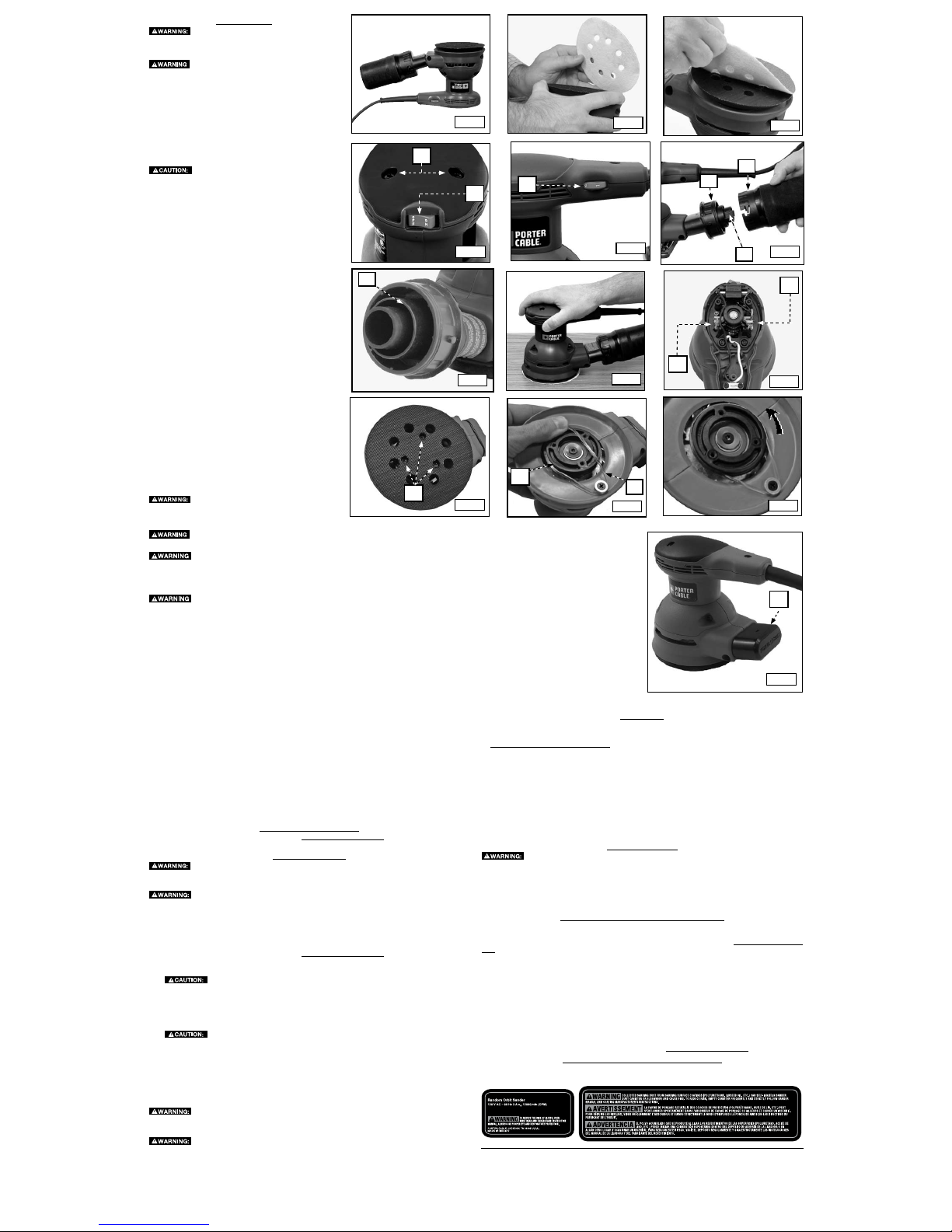
ATTACHING ABRASIVE PAPER
Model 343 and 343VS: Use 5" (127 mm) sanding discs with
an 8-hole dust extraction pattern which attach to the sander
with hook and loop.
Model 344: Use 5" (127 mm) sanding discs with an 8-hole
dust extraction pattern which attach to the sander with
pressure sensitive adhesive.
Model 353: Use 5" (127 mm) no-hole sanding discs which
attach to the sander with pressure sensitive adhesive.
Turn off and unplug the tool before making
any adjustments or removing or installing attachments or
accessories. Be sure the switch is in the "OFF" position.
1. Turn the sander over so that the sanding pad is facing
upward (Fig. 1).
2. Clean the dust from the vinyl pad face.
3. Hold the pad with one hand to keep it from rotating (Fig.
2).
4. With the other hand, align the holes and place the disc
directly on top of the pad (Fig. 3).
NOTE: Do not use the sanding screen (the screen used for
sanding drywall) directly on the hook and loop pad. The
screen will not hold and will damage the hooks on the pad.
The hooks will wear very rapidly if left in contact with the
work surface while the tool is operating.
SWITCH
To turn the unit on, depress the "ON" side of the dust
protected switch (B) Fig. 4. To turn the tool off, depress the
"OFF" side of the switch.
SPEED CONTROL DIAL (343VS only)
The speed control dial (A) Fig. 5 allows you to increase or
decrease the speed from 7,000-12,000 orbits per minute.
The optimal speed setting for each application is very
much dependent on personal preference. Generally, you
will want to use a higher setting on harder materials and
a lower setting on softer materials. Material removal rate
increases as speed increases.
PAD BRAKE
These sanders are equipped with a pad brake that prevents
over-speeding of the pad. If the tool is lifted off the work
surface while the motor is running, the brake will limit pad
rotation to no more than 400 RPM.
The pad brake uses a belt to provide the braking action.
Eventually, this belt may require replacement. If the brake
fails to limit pad rotation, send the sander to a Porter-Cable
service facility or replace the belt yourself using the information in "BELT REPLACEMENT" in the maintenence
section of this manual.
DUST COLLECTION
To reduce the risk of injury, turn unit off
and disconnect it from power source before installing
and removing accessories, before adjusting or when
making repairs. An accidental start-up can cause injury.
To reduce the risk of serious personal injury, NEVER operate this tool with perforated
paper unless the dust collection system is in place.
Empty dust collection system frequently, especially when sanding resin-coated surfaces such as polyurethane, varnish, shellac, etc. Dispose of coated dust particles according to
the finish manufacturer’s guidelines, or place in a metal can with a tight fitting metal lid. Remove
coated dust particles from the premises daily. The accumulation of fine sanding dust particles may
self ignite and cause fire.
Do not use a dust collection device when sanding metal. Doing so creates a fire hazard,
which may cause serious personal injur y and/or damage to the tool.
To use the dust collection system, install the dust container assembly (A and B) Fig. 6 on the dust
port as far as it will go.
NOTE: To use your shop vacuum with the dust collection system, remove the dust container (B) Fig.
6 by twisting it and pulling it away from the adapter. Remove the black tag (J) Fig. 6, and attach your
vacuum hose directly to the adapter port (C) (Fig. 7).
To empty the dust container, remove it and empty it into a trash receptacle.
NOTE: Dust collection is not possible with the 353 Model sander becuase its dust port (C) FIg. 12 is
covered and there are no holes in the backing pad.
USING THE SANDER
To operate your sander, grasp it as shown in Fig. 8 and turn it on. Move it in long, sweeping strokes
along the surface, letting it do the work. Pushing down on the tool while sanding actually slows the
removal rate and produces an inferior quality surface. Be sure to check your work often. This sander
is capable of removing material rapidly, especially with coarse paper.
The random orbital action of your sander allows you to sand with the grain or at any angle across
it for most sanding jobs. To produce the best finish possible, start with coarse grit sandpaper and
change gradually to finer and finer paper. Vacuum and wipe the surface with a tack cloth between
grit steps. Your sander is designed to sand into small or confined areas. Its small size and light
weight make it ideal for overhead work.
The rate at which the dust container fills will vary with your workpiece and the coarsness of the
sandpaper. For best results, empty the container frequently. When sanding painted surfaces (see the
additional precautions for sanding paint), you may find that the sandpaper clogs with paint. A heat
gun will work much better to remove paint before sanding. FOLLOW ALL THE SAFETY INSTRUC-
TIONS IN THE HEAT GUN INSTRUCTION MANUAL.
TROUBLESHOOTING
For assistance with your tool, visit our website at www.deltaportercable.com for a list of service centers,
or call the Porter-Cable Customer Care Center at (888) 848-5175.
MAINTENANCE
To reduce the risk of injury, turn unit off and disconnect it from power source before
installing and removing accessories, before adjusting or when making repairs. An accidental start-
up can cause injury.
ALWAYS USE SAFETY GLASSES. Everyday eyeglasses are NOT safety glasses. Also use
face or dust mask if cutting operation is dusty. ALWAYS wear certified safety equipment:
• ANSI Z87.1 eye protection (CAN/CSA Z94.3)
• ANSI S12.6 (S3.19) hearing protection
• NIOSH/OSHA/MSHA respiratory protection.
REPAIRS
For assistance with your tool, visit our website at www.deltaportercable.com for a list of service centers,
or call the Porter-Cable Customer Care Center at (888) 848-5175.
CHANGING BACK-UP PAD
1.
DISCONNECT TOOL FROM POWER SOURCE.
2. Grasp pad with hand and use phillips screwdriver to remove three pad retaining screws (S),
Fig. 9A.
3. Lift pad from sander.
4. Reverse procedure to install new pad. Tighten pad retaining screws 25 to 30 in-lbs.
BELT REPLACEMENT
1.
DISCONNECT TOOL FROM POWER SOURCE.
2. Remove back-up pad (see CHANGING BACK-UP PAD).
3. Remove the old belt and clean the belt mounting area.
4. Position the new belt (B) around pulley (H) Fig. 10, and start it onto the shoulder of the pad
support.
5. Rotate the pad support as you “walk” the belt onto it (see Fig. 11).
6. Reassemble back-up pad (see CHANGING BACK-UP PAD).
CLEANING
Periodically blowing dust and chips out of the motor housing using clean, dry compressed
air is a suggested maintenance procedure. To reduce the risk of serious personal injury, ALWAYS wear
ANSI Z87.1 safety glasses while using compressed air.
When cleaning, use only mild soap and a damp cloth on plastic parts. Many household
cleaners contain chemicals which could seriously damage plastic. Also, do not use gasoline, turpentine,
lacquer, paint thinner, dry cleaning fluids or similar products which may seriously damage plastic parts.
NEVER let any liquid get inside the tool; NEVER immerse any part of the tool into a liquid.
FAILURE TO START
Should your tool fail to start, check to make sure the prongs on the cord plug are making good contact in
the outlet. Also, check for blown fuses or open circuit breakers in the line.
Fig. 2
A
A
A
A
B
S
H
B
C
C
A
B
J
Fig. 1
Fig. 3
Fig. 4
Fig. 5
Fig. 6
Fig. 7
Fig. 8
Fig. 9
Fig. 10
Fig. 11
Fig. 12
Fig. 9A
 Loading...