

Page 1

LC80i-IP
LC265i-IP
Active In-Wall/In-Ceiling Speakers
LCi-IP SERIES
Owner’s
Manual
Page 2
ENGLISH
7.43
188.7
3.18
80.8
7.43
188.7
3.18
80.8
3.18
80.8
A
B
1
2
CHANNEL 1
CHANNEL 2
NETWORK IN
COMM
CONTROL CFG CHANNEL
Y
N
A
B
1
2
OPTI
CHANNEL 1
CHANNEL 2
NETWORK IN
COMM
A
B
1
2
CONTROL CFG CHANNEL
Y
N
A
B
1
2
IMPORTANT SAFETY INSTRUCTIONS
READ BEFORE OPERA
1. Read these instructions.
2. Keep these instructions.
3. Heed all warnings.
4. Follow all instr
5. Do not use this apparatus near water.
6. Clean only with dry cloth.
7. Do not block any ventilation openings. Install in
accordance with the manufacturer’s instructions.
8. Do not install near any heat sources such as radiators,
heat registers, stoves,or other apparatus
(including amplifiers) that pr
9. Do not defeat the safety purpose of the polarized or
grounding-type plug. A polarized plug has two
blades with one wider than the other. A grounding
type plug has two blades and a third grounding
prong. The wide blade or the third prong are
provided for your safety. If the provided plug does
not fit into your outlet, consult an electrician for
replacement of the obsolete outlet.
10. Protect the power cord from being walked on or
pinched particularly at plugs, convenience
receptacles, and the point where they exit
from the apparatus.
11. Only use attachments/accessories specified
by the manufacturer.
12. Use only with the cart, stand, tripod, bracket, or table
specified by the manufacturer, or sold with the
apparatus. When a cart is used, use caution when
moving the cart/apparatus combination to avoid
injury from tip-over.
13. Unplug this apparatus during lightning storms or
when unused for long periods of time.
14. Refer all servicing to qualified service personnel.
Servicing is required when the apparatus has been
damaged in any way, such as power-supply cord or
plug is damaged, liquid has been spilled or objects
have fallen into the apparatus, the apparatus has
been exposed to rain or moistur
normally, or has been dropped.
15. WARNING: To reduce the risk of fire or electric shock,
this apparatus should not be exposed to rain or
moisture and objects filled with liquids, such as
vases, should not be placed on this apparatus.
16. To completely disconnect this equipment from the
mains, disconnect the power supply cor
the receptacle.
17. The main plug of the power supply cord shall
remain readily operable.
ARNING
W
To prevent injury, this apparatus must be securely
attached to the ceiling/wall in accor
the installation instructions.
TING EQUIPMENT
uctions.
oduce heat.
e, does not operate
d plug from
dance with
Product Disposal - Certain international, national
and/or local laws and/or regulations may apply
regarding the disposal of this product. For further
detailed information, please contact the retailer
e you purchased this product or the Polk
wher
Audio Importer/Distributor in your country
listing of Polk Audio Importer/Distributors can
be found on the Polk Audio website
www.polkaudio.com or by contacting Polk Audio at
5601 Metro Drive, Baltimore, Maryland 21215,
USA— Phone: +1 410 358-3600.
TAKE INVENTORY
Inside each LCi-IP speaker container, you should find the
following:
1. One LC
i-IP speaker
2. Performance Optimization Wizard – CD-ROM
3. Mating connectors for amplifier’s power section
4. Mounting template
5. Paint mask
6. Grille
i-IP manual
7. LC
8. Laminated configuration setup card
9. Registration car
Note: If you ar
d
e setting up L
C
IP speakers to be
icontrolled via an IP-network such as NetStreams™,
you will have to purchase a network decoder card.
The network decoder car
d is sold separately.
Important Note: If anything is missing or damaged, or
if your LC
i-IP speaker fails to operate, notify Polk Audio
Installer Support Services immediately at 800-377-7655.
GENERAL DESCRIPTION
Polk Audio LCi-IP ultra high performance loudspeakers
are among the world's first active IP in-wall and
in-ceiling loudspeakers. They were created for IP-networked systems but are also compatible with analog
systems. A network decoder card (sold separately), builtin Digital Signal Pr
ocessor (DSP) and the Per
Optimization Wizard enables every LC
set up for maximum performance in any room environ-
for
i-IP speaker to be
. A
mance
ment. What’s more, LC
d-winning reputation, because they use the same
awar
driver technologies as Polk Audio's awar
high-end LS
i Series.
i-IP speakers already come with an
d winning
The built-in DSP controls the electronic crossover,
frequency equalization, bass enhancement and room
optimization. Performance Optimization Wizard software,
which integrators can use via a USB por
on the inter
net through a network such as NetStreams™,
t and a PC, or
optimizes each speaker for its location and room environment. Depending on the speaker and its location, and the
configuration of the room and its acoustics, you may
be asked to take a series of measur
ements, which
you would then input into the Performance
Optimization Wizard.
ACTIVE IP LOUDSPEAKER FEATURES
ith an open architecture network decoder card such
• W
as the StreamNet™ card and an Ethernet cable,
integration with any system capable of streaming
packet-switched audio in WAV or MP-3 format and
TCP-IP control is possible.
• Pure digital signal all the way to the power amplifier
outputs, with no losses and superb fidelity.
• Speakers automatically announce themselves to
an open architective network via a network
decoder card.
Self Amplified
• Amplifier at speaker minimizes losses associated
with long runs of cable and passive crossover parts,
creating higher fidelity.
• Efficient, cool running digital amplifiers.
• Bi-amplified (LC265
i-IP is tri-amplified) with electronic
crossover minimizes power loss and phase shift
for better sound.
• High Power for incredible dynamic range.
• Powered by 48V DC local power supply
(sold separately).
Built-In DSP
• DSP allows unprecedented room optimization EQ for
sound quality that can exceed free-standing speakers.
d
mance Optimization W
Pefor
mance Optimization W
•Use the Per
for
izar
d softwar
izar
e
with a PC connected via a mini USB port located on
the front baffle of each speaker, or through the internet
when the speakers ar
network decoder car
e used in an IP network via a
s user inter
d. The softwar
e’
face
makes the speaker position and room acoustics
optimization virtually foolproof.
LCi-IP Speaker Technology:
• Foamed Polypropylene Dynamic Balance™ Cones
(LC265
f and yet surprisingly lightweight-20%
i-IP): stif
lighter than conventional polypropylene and 35%
lighter than aluminum cones for spectacular midrange
clarity, punchy bass and high efficiency.
• Casket Basket
moving par
®
: composite driver baskets keep
ts in rigid alignment and damps
performance-robbing resonance.
• The LC265i was the first in-wall speaker to feature
the patented Power Port™ bass venting system for
superior bass response with low distortion.
• Available Performance Enclosures deliver consistent
room-to-room performance, improves bass and
sound transmission.
• Round model (LC80
i-IP) features 15° Driver Offset
for better midrange clarity and imaging anywhere
oom.
in the r
• Ring Radiator tweeters (the same tweeters used in
the LSi Series) for smooth, extended highs with
incredible accuracy and astonishing detail.
POWER RATINGS
LC265i-IP—200W FTC/speaker with < 0.5%
THD+N (25W tweeter 4 Ohms,
75W mid 8 Ohms, 100W woofer
8 Ohms)
i-IP—100W FTC/speaker with < 0.5%
LC80
THD+N (25W tweeter 4 Ohms,
75W mid 4 Ohms)
LC265i-IP POWER REQUIREMENTS
PER SPEAKER
Voltage Input: 48VDC
Current Draw: 4.5A
LC80i-IP POWER REQUIREMENTS
PER SPEAKER
Voltage Input: 48V or 28VDC
Current Draw: 2.3A@48V or 3.8A@28V
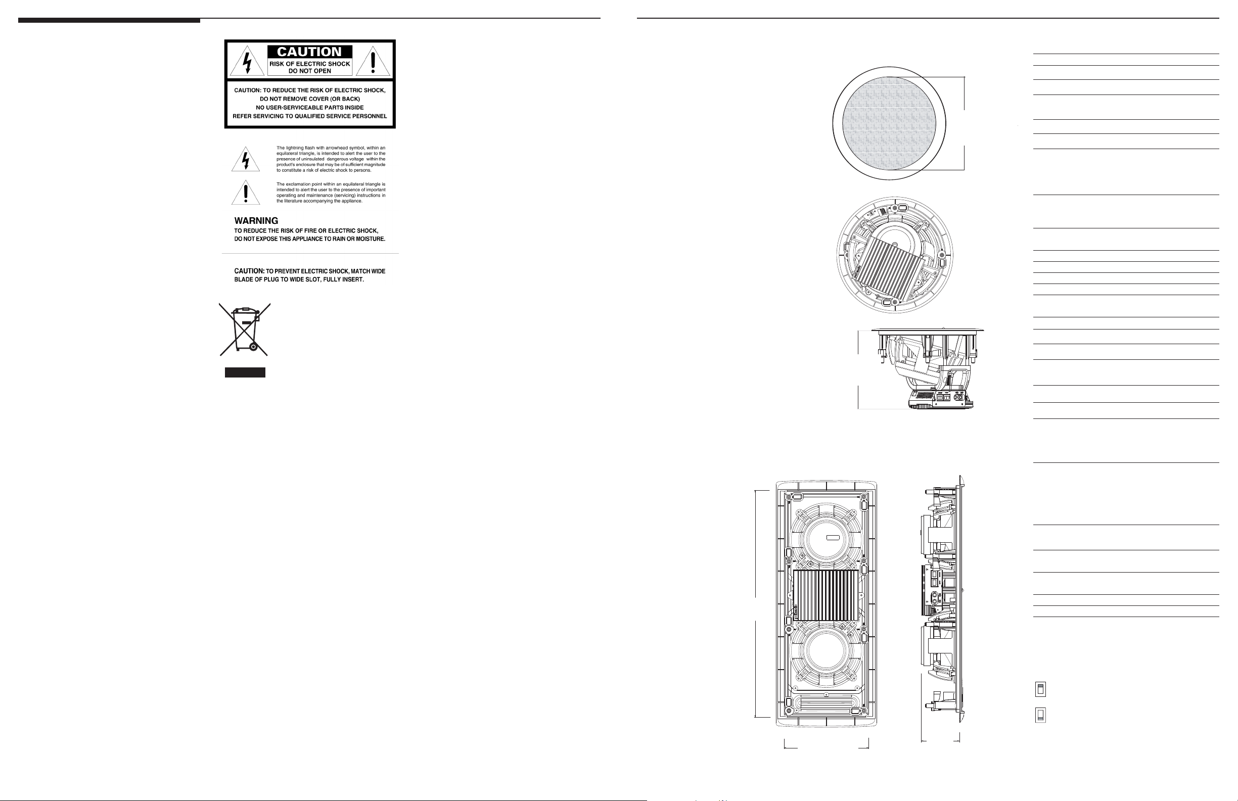
Cutout Dimension
19 1/4"(48.9 cm)
Cutout Dimension
7 1/4"(18.4 cm)
Total
Depth
7"
(17.8 cm)
otal
T
Depth
3 9/16"
(9.1 cm)
Cutout
Dimension
7 3/8"
(18.7 cm)
LCi-IP SERIES SPECIFICATIONS
Model LC80i-IP
eq. Response variable
Fr
Freq. Response -3dB Limit variable
Analog Audio Signal < 2V RMS
Voltage Input (Line-Level)
Amplifier SNR > 90dB
mware Upgradeable yes
Fir
Protection thermal, short-
circuit, current
overdraw, clipping
compresser/limiter
Drive Unit Mid-Bass 1–8"(20.3cm) mineral
filled polypropylene
cone, rubber surround
Tweeter 1" (2.5cm) ring radia-
tor in swivel mount
Outside Dimensions 10 3/4" Dia (27.3cm)
Cutout Dimensions 7 3/8" (18.7cm)
Mounting Depth (with1/2" drywall) 6 1/2" (16.51cm)
Speaker Weight 4.8 lbs.
Model LC265i-IP
Freq. Response variable
Freq. Response -3dB Limit variable
Analog Audio Signal < 2V RMS
Voltage Input (Line-Level)
Amplifier SNR > 90dB
Firmware Upgradeable yes
Protection thermal, short-circuit,
current overdraw,
clipping compresser/
limiter
Drive Unit Mid-Bass 1–6.5"(16.5cm) aerat-
ed polypropylene
cone, rubber surround
1–6.5"(16.5cm) aerat-
ed polypropylene
ound
ubber sur
cone, r
weeter 1" (2.5cm) ring radia-
T
r
tor in swivel mount
Outside Dimensions 8 1/2" X 20 7/8"
(21.59cm X 53.04cm)
Cutout Dimensions 7 1/4" X 19 1/4"
(18.42cm X 48.90cm)
3 1/16" (7.78cm)
Mounting Depth (with 1/2" dr
ywall)
Speaker Weight 8.7 lbs.
INHERENT DELA
Y
Inherent delay for each speaker is:
-2.5 milliseconds
-4.4 milliseconds
Any other delay is fr
om the MRAV.
2 Polk Audio Customer Service: 1-800-377-7655 (Outside US & Canada: 410-358-3600) Monday-Friday, 9:00 AM-6:00 PM EST, polkcs@polkaudio.com
For more information visit our website at www.polkaudio.com 3
Page 3
INSTALLING LCi-IP SPEAKERS
INSTALLATION RECOMMENDATION
FOR OPTIMUM PERFORMANCE
Note: Polk Audio performance enclosures are
Important Note: If installing LCi-IP speakers in
an external wall, the operating ambient temperature of
the speakers is 0-50° C (32-122° F). For most types of
construction, the external walls will be insulated,
but it
is important that insulation does not come in contact with the speaker’s amplifier.
Cable runs up to 100 feet should have a capacitance
of 20pF/ft. For cable runs greater than 100 ft. call
Customer Serivce at 1-800-377-7655.
USB Connection
USB 1.1, 5-wire, USB to mini-USB cable.
sold separately.
Polk Audio Per
formance Enclosures offer the best
possible sound quality with pre-construction and major
renovation installations. They are perfect volume cabinets that provide LC
i-IP speakers with the ideal volume
and internal damping material for optimum bass performance. They are constructed of rigid MDF and extensively braced to ensure that all of the speaker's energy
works to produce tight, clean, low distortion bass. Polk
provides brackets, gaskets and all the hardware you
need to do a quick and rattle-free installation. LC
i-IP
Performance Enclosures guarantee the most consistent,
dynamic, full-spectrum sound with superior bass extension. As an added bonus, homeowners will enjoy
Pre-construction Brackets are available to locate the
speaker and tie of
finish their work. Order the LC
f wires before the drywall installers
i-IP Pre-Construction
Brackets by contacting Polk Audio's Sales Department
at 800-638-7276.
Good Sound
Cut a hole for the speaker, feed the wires, and simply
drop the speaker in. Polk Audio's unique, rotating cams
secure the speaker safely with no extra assembly or
i-IP Loudspeakers are designed to outperform
mess. LC
any other custom install speaker, even when they're
simply dropped into the wall or ceiling.
Power Lines
ecommendations are for all connections
These r
from the power supply to each speaker:
Wire gauge/ Wire Length
# of Conductors
Optimal 14/4 1’
Acceptable 16/2 150’
Cable Installation Tips
superior room-to-room sound isolation.
OTHER OPTIONS
Better Sound
When you can't install a Performance Enclosure but
want to get better bass, install fire breaks above and
below the speaker position to make an ideal-volume
enclosure. Also, a layer of fiberglass or Dacron
®
behind the speaker helps.
Note: Leave space around the speaker’s amplifier;
insulating material must not come in contact
with the amplifier.
WIRE RECOMMENDATIONS
Network Line
Shielded Cat-5 cable with RJ-45 connectors.
Wiring termination convention should be the
same at both ends of the cable.
COMM Line
Shielded Cat-5 cable with RJ-45 connectors.
Wiring termination convention should be the
same at both ends of the cable.
Analog Line
Low capacitance multi-stranded RCA shielded cable.
• Observe the proper polarity at each connector.
all insulation should never come in contact with
• W
the amplifier located on the back of each speaker.
• Never kink or bend any cable, nor should any
cable interfere with other cables.
• Never try to make a short cable reach, ever.
• Avoid long cable runs if possible — the shorter
the cable, the better the sound quality. Do,
however, ensure that your cables are long enough.
• Cable should be at least 3 feet away from
fluorescent light boxes and other sources of
electrical interference.
• Label both ends of each cable.
• Always keep AC power cords and analog
power cords separate.
CONNECTION AND CONTROL OPTIONS MATRIX
Speaker Input Switch Setting Control
1a: NETWORK PAIR CH 1 CH 2 Network Control CFG Channel Comm USB
ol on Left)
(Contr
1b: NETWORK PAIR CH 1 CH 2 Network Control CFG Channel Comm USB
(Control on Right) Left Speaker N B 1 x
2: NETWORK CH 1 CH 2 Network Control CFG Channel Comm USB
(Independent Contr
3a: ANALOG PAIR CH 1 CH 2 Network Control CFG Channel Comm USB
(Control on Left) Left Speaker x x Y B 1 x
3b: ANALOG PAIR CH 1 CH 2 Network Control CFG Channel Comm USB
(Control on Right) Left Speaker N B 1 x
4a: ANALOG PAIR CH 1 CH 2 Network Control CFG Channel Comm USB
(Control on Left) Left Speaker x Y A 1 x
4b: ANALOG PAIR CH 1 CH 2 Network Control CFG Channel Comm USB
(Control on Right) Left Speaker x N A 1 x
5a: ANALOG (Independent CH 1
Control when used with Speaker
3a or 3b)
5b: ANALOG (Independent CH 1 CH 2 Network Control CFG Channel Comm USB
Control when used with Speaker x Y A 1 x
4a or 4b)
ol)
Left Speaker
Right Speaker N B 2 x
Right Speaker x Y B 2 x
Left Speaker
Right Speaker
Right Speaker x x Y B 2 x
Right Speaker
Right Speaker
x Y B 1 x
x N A 2 x
x
CH 2
x
x
Network Control CFG Channel Comm USB
Y
Y B 1 x
N
Y
B 1 x
B
A
2
2 x
x
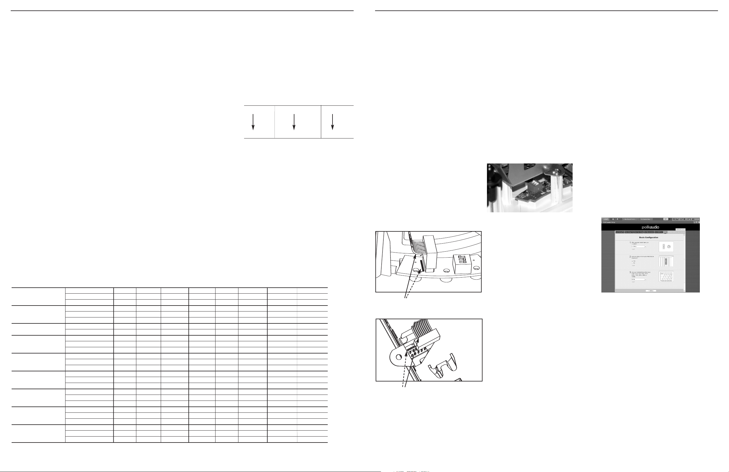
INSTALLING THE
NETWORK DECODER CARD
Introduction
You will need to install a netword decoder card to
use the “network.” Follow the directions below to
install the card. There is also a series of schematic
diagrams (on page 38) to help you properly connect
the speakers to a network or analog system.
Note: A network decoder card is not needed to use
the analog RCAs.
Step 1: Disconnect all cables.
Step 2: Remove the (4) screws holding the heat
sink to the amplifier housing. Set the
screws safely aside.
Step 3: Remove the amplifier and loose cables
from the amplifier housing.
Step 4: Remove the two screws from the two
metal standoffs located on the PCB.
Step 5: Install the network decoder card on the
standoffs, mating the two sides of the
40-pin connector
. Press down and ensure
that the card snaps onto the two
plastic standoffs.
Step 6: Secure the network decoder card by
reinserting the two standoff screws
into the two metal standoffs.
Step 7: Reinstall the amplifier onto the amplifier
chassis (reversing steps 1, 2 & 3).
Note: Illustration shows orientation of ribbon
connector to silkscreen marking on PCB.
Note: Illustration shows orientation of ribbon
connector to silkscreen marking on amplifier.
CONNECTING LCi-IP SPEAKERS TO
A NETWORK OR ANALOG SYSTEM
This is the list of speaker connection options, which
are shown schematically on pages 39-43:
1a. Network pair (Control on Left)
1b. Network pair (Control on Right)
2. Network (Independent Contr
ol)
3a. Analog pair (Control on Left)
3b. Analog pair (Control on Right)
4a. Analog pair (Control on Left)
4b. Analog pair (Control on Right)
When using a Center Channel with an
analog pair
5a. Analog (Independent control when used
with either Hookup 3a or 3b)
5b. Analog (Independent control when used
with either Hookup 4a or 4b)
Important Note: Switch settings are located on
the back of the speaker baffle.
Reset Button Reminder
Note:
Each speaker has a RESET BUTTON,
which is accessible through a clearly-marked hole
on the front of the speaker.
Engage the RESET BUTTON whenever you:
• Reconfigure the switch settings.
• Update the firmware on the network decoder card.
• Update the amplifier’s firmware.
PERFORMANCE OPTIMIZATION
WIZARD PROGRAM USER’S GUIDE
Computer Requirements
Operating System: W
indows XP
USB Port : 5-wire USB 1.1 connector
Hard drive: 5 Megabytes
Required Speaker Connections
o connect your computer to the speaker
T
,
you have two options:
1. USB port
2. Ethernet jack with network decoder card
(sold separately).
LCi-IP PERFORMANCE
OPTIMIZATION WIZARD PROGRAM
Polk Audio provides the Performance Optimization
Wizard on CD-ROM. This program enables you to
optimize the performance characteristics of Polk
i-IP speakers specifically to their location
Audio LC
in a given room and to the physical characteristics
oom.
of that r
You can also download the Performance Optimization
Wizard from our website (www.polkaudio.com).
• For maximum accuracy, answer as many
questions as possible. Do not ”skip” questions
unless the information is unavailable.
• Should you have any questions before or during the
setup process, please feel free to contact Polk Audio
Installer Support Services at 1-800-377-POLK.
Walking Through the Room
Optimization Choices
• This program can be used for installing and
setting up in-wall or in-ceiling LC
i-IP speakers
and asks a series of basic configuration
questions and a series of questions about
the room environment (figure1).
Figure 1
• Depending on the speaker you’r
e installing,
its location and the room, you may be asked for
a series of measurements, including the height
of the listening r
oom's ceiling, distances from
walls, ceiling and floor to the speaker(s), as well
tical and horizontal angles of speakers
as ver
ou may also be
elative to the listening ar
r
ea. Y
asked to provide measurements for the height,
width, depth and center of the listening area
e 2).
(figur
4
Polk Audio Customer Service: 1-800-377-7655 (Outside US & Canada: 410-358-3600) Monday-Friday, 9:00 AM-6:00 PM EST, polkcs@polkaudio.com
For more information visit our website at www.polkaudio.com 5
Page 4
Making A Speaker Configuration File Offsite
INTERPRETING THE LEDS
FAQs
Figure 2
Note: Most measurements will be taken from
the center of the tweeters. To take these measurements, you will need: a tape measure and a
protractor. You may also be able to determine
the necessary measurements from a blueprint
or floorplan.
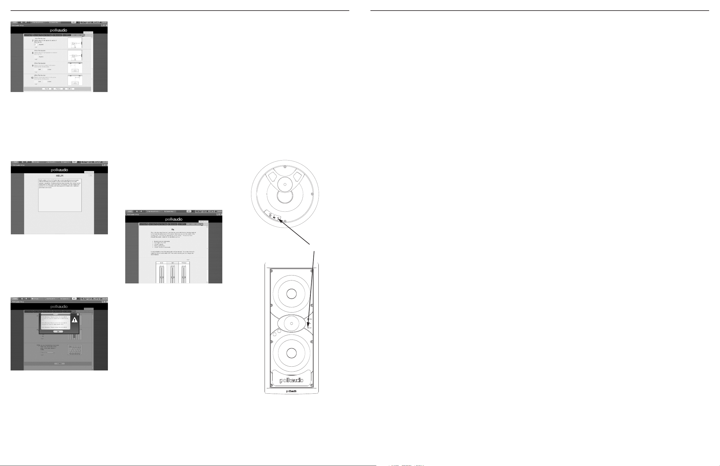
Figure 3
• Included with each setup question and physical
measurement, there is a help link that defines
a particular question or measurement in more
detail. Click on the link to call up the help
screen (figure 3).
To help you work more efficiently and save time,
you can make a speaker configuration file offsite.
You will need to have installed the speakers, be
familiar with the room environment and have taken
the necessary measurements. Once on site, you can
download the file and audition the system, making
any final EQ adjustments as deemed necessar
y.
Auditioning and Final EQ Adjustments
Adjusting the EQ gives you the opportunity to fine
tune the system’s performance (figure 5). You should
be in the center of the listening area, with the volume set at an appropriate level. Play audio through
the system, and listen for problems such as:
Muddy vocals or instruments
Too bright/Too dull
”Boomy” sounds
Thin sounding bass
”Harsh” vocals or instruments
If the system sounds good,no changes are
recommended. When you have finished
listening, press ”Finish.”
Figure 5
tant Note:
Impor
Always save your newly
configured settings to the DSP.
An LED indicator tells you the status
of each speaker:
An ORANGE LED indicates the speaker
is in STANDBY.
A GREEN LED indicates the speaker is ON.
A RED LED indicates the speaker is in
PROTECTION mode.
Reset Button Reminder
Engage the RESET BUTTON whenever you:
• Reconfigure speaker switch settings.
• Update the firmware on the network decoder card.
• Update the amplifier’s firmware.
Note: Each speaker has a RESET BUTTON, which
is located on the front of the speaker.
Reset button
Will the speakers work with my
current MRAV system?
Please check with your MRAV Authorized Installer.
Is there any inherent delay in the system?
Inherent delay for each speaker is based on position
of configuration switch (CFG). W
ith CFG switch set to
“A,” the delay from input to speaker output is 2.5
milliseconds; with CFG switch set to “B,” delay is
4.4 milliseconds. There is no delay from speaker to
speaker. Any other delay is from the AV system.
How much heat can these speakers take?
The ambient operating temperature range of the
LC
i-IP speakers is 0-50C (32-122F).
What about the amplifier and wall insulation?
The amplifier should never come into contact
with any wall insulation.
What are the switch settings on the back of the
speaker’
s baffle for?
These settings affect the configuration of the
speakers (see page 5).
Do I need to run the Performance Optimization
Wizard in order to listen to the speakers?
No. The speakers are loaded with factory default
settings. These speakers were designed to sound
great right out of the box. If you want them to sound
better or configure them to be used with your MRAV,
then you will need to use the software.
Can I run analog lines to each speaker but use
the COMM line to control everything?
Yes, this is a supported configuration (see page 40).
What gauge wire do you recommend for the
power connections?
We recommend 14 gauge wire. You may use
16 gauge, but at a cost to performance.
If I install a LC80i-IP in the ceiling but don’t
connect via a network decoder card, can I use
om my
eless USB connector to contr
a wir
ol it fr
computer?
No. The speaker is not an USB host. A wired
connection to a PC is r
equired.
What happens to the speaker settings if
I temporarily lose power?
If you are using the default settings or saved any
settings to the DSP from the POW, they will be
present in the system when you power back up.
We recommend that you also save your POW
settings by storing the configuration file on your
hard drive. This is an available option inside of
the Performance Optimization Wizard program.
Can I install a speaker under a water source,
such as putting an LC80
i-IP in a ceiling under
a bathroom tub?
We do not recommend installing any speaker
near a water source because of potential leaks.
Can I mount LCi-IP speakers in an external
wall?
Yes, as long as the wall’s insulation doesn’t
come in contact with the amplifier.
Can I mount LCi-IP speakers so that
they are outside?
No. These speakers are for indoor use only.
Whose power supply can I use?
You can use the Polk Audio SPS-1 power supply or a
similar power supply such as an available NetStreams
power supply. Be aware that the SPS-1 can power
both the LC265
i-IP and LC80i-IP speakers. Be sure to
check the voltage and current ratings on third party
power supplies to achieve optimal performance.
Can I put the SPS-1 power supply on a power
circuit with other devices, or does it need its
own circuit?
The power supply does not need to be on its own
circuit, but ensure that you are not exceeding the
current draw limitations of the circuit.
Should I use a surge protector?
ecommend that you always use a
e r
es. W
Y
surge protector.
e 4
Figur
• An “Error Message” will be displayed if you
do not supply information. For some r
equested
measurements you may not be able to supply
the requested information, and you may check
the appropriate “skip question” box. When an
“skip question” box is checked, no error
message is displayed (figure 4).
6 Polk Audio Customer Service: 1-800-377-7655 (Outside US & Canada: 410-358-3600) Monday-Friday, 9:00 AM-6:00 PM EST, polkcs@polkaudio.com
What is the r
ess the RESET button whenever you r
Pr
eset button for?
econfigur
the speaker switch settings, update the firmware
on the network decoder card or update the
e.
mwar
amplifier’
s fir
e
For more information visit our website at www.polkaudio.com 7
Page 5

TROUBLESHOOTING
TROUBLESHOOTING CONTINUED
Problem Possible Reason(s) Solution
No audio Audio signal is not connected to the speaker. Make sure that the speaker is connected to the audio source using RCA
cables or a RJ45 equipped Cat-5 cable. Make sure that the configuration
switches are set appropriately.
The speaker’s software is not configured to Make sure to use the Performance Optimization Wizard when connecting to
work with the MRAV. an IP-based network, such as NetStreams’ DigiLinX network. Also make
sure to use any set-up software required for configuring the MRAV.
The speaker’s configuration switches are not Check the current hook-up configuration against the possibilities
set correctly. listed on page 5 to make any necessary adjustments. Once complet-
ed, make sure to press the RESET button on the CONTROL speaker,
located on the speaker’s front baffle.
No power. Make sure that the power cable is connected to both the power supply
and the speaker and that the connectors are fully inserted on both
ends. Make sure that the power supply is on and that there are no
kinks in the power wire (i.e. it is not broken).
The MRAV does not recognize the speaker. Make sure to use any set-up software required for configuring the MRAV.
Also make sure that the appropriate network decoder card has been
installed into the CONTROL speaker if audio is coming to the speaker
using the speaker’s NETWORK connection.
Speaker is playing the The speaker’s CHANNEL switch is in Set the CHANNEL switch to the opposite position and press the
wrong audio channel. the wrong position. RESET button on the front baffle of the CONTROL speaker.
The wiring for the speaker is incorrect. Make sure that the cable connecting the speaker to the MRAV
is sending the desired audio channel.
No control Loose or bad NETWORK connection. Make sure that the RJ45 equipped Cat-5 cable has been tested for
continuity. The pin-out for both ends of the cable should match.
USB connection is bad. If you intend to use the USB connection for control, make sure it is
plugged into the speaker and your computer.
No power Loose or bad POWER connection. Make sure that the power cable is connected to both the power supply
and the speaker and that the connectors are fully inserted on both ends.
Power supply’s circuit might be off. Check first to make sure the power supply’s circuit’s fuse is ON. Next,
make sure that the power supply is on and that there are no kinks in
the power wire (i.e. it is not broken).
Hum on audio Grounding problem. Make sure that there are no ground-loops at the audio source. Also make
sure that the power supply that is being used has a single-ended output.
Audio signal cable is not shielded and is Check all wired connections and make sure that the audio signal cable is
routed next to a power cable. shielded properly. If it is not, either replace the cable or make sure that the
cable is at least 6-inches away from any power cables as the frequency (50
ce will be audible at the speakers.
eset EQ. While the
y pr
mance Optimization W
for
izar
d. This will
Poor sound
mance Optimization W
for
Per
not been used.
izar
d has
or 60 Hz) of the AC power sour
These speakers have been loaded with a factor
EQ provides high performance in most situations, you are strongly
encouraged to use the Per
modify the EQ of the speakers to the installed location and optimize
formance of the speakers.
the per
ong or inaccurate values have been enter
r
W
mance Optimization W
into the Per
for
izar
ed
d.
Make sure that the values entered into the Performance Optimization
e as accurate as possible. A summary page is shown once
d ar
izar
W
the wizard is completed. Check over the answers in the summary
e they ar
mance Optimization W
for
izard, restore the speaker’s factory
mance Optimization W
for
Per
izar
page to make sur
d
Using the Per
ect.
r
e cor
is malfunctioning. default EQ settings and save them to the speaker’s DSP. Then, please contact
mation.
ther infor
e in the audio chain,
Audio sour
ce is of bad quality
our Customer Ser
.
It is quite possible that the audio sour
vice depar
tment at 1-800-377-POLK for fur
ce or some wher
there is something that is malfunctioning or is performing poorly. Due to the
C
high quality and r
evealing natur
check the various components and cables of the MRA
e of the L
oduct, it may be necessar
i-IP pr
V for conflicts or issues.
y to
Problem Possible Reason(s) Solution
No LED Room is too bright. The LED found on the front baffle of the speaker is intentionally soft as
to not distract the user during operation. Make sure the speaker grill
is removed and look closely at the LED. If the power connections are
correct, the LED should be ON.
Loose or bad power connection. Refer to the “No Power” section of this table.
Defective LCi-IP product. Double-check the wiring for the speaker. If all looks good, please
contact our Customer Service department at 1-800-377-POLK for
further instructions.
LED is Red Short circuit exists. Check all cables and make sure there are no stray strands of copper or other
conductive material that are inadvertently connecting two conductors that
should not be electrically connected.
Amplifier is overheating. Check to make sure that no insulation is coming in contact with the speaker’s
amplifier. Next, make sure that no additional heat source is located near the
speaker. If the amplifier continues to overheat, please contact our Customer
Service department at 1-800-377-POLK for further instructions.
TROUBLESHOOTING FOR THE PERFORMANCE OPTIMIZATION WIZARD
Problem Possible Reason(s) Solution
Error message during installation. Firewall or antivirus software is causing Make sure to exit all programs and disable all firewall or antivirus
installation problems. software prior to running the installation program.
Microsoft
®
Windows®XP crashes. Possible Microsoft®Windows®XP bug. Make sure that the computer running the software is up-to-date and has
all appropriate fixes and patches as recommended by Microsoft®.
Computer crashes when you try Incompatible Operating System. This program can only work using Microsoft
®
Windows®XP. It may not be
to run program. compatible with Emulators.
Using the software is not changing The software is working offline. Make sure that the computer using the software is connected to the
the way the speakers sound. CONTROL speaker. Next, restart the software program. If the program asks
you if you would like to work offline, you might either have a conflict in your
port configurations or the correct drivers may have not been loaded.
8 Polk Audio Customer Service: 1-800-377-7655 (Outside US & Canada: 410-358-3600) Monday-Friday, 9:00 AM-6:00 PM EST, polkcs@polkaudio.com
For more information visit our website at www.polkaudio.com 9
Page 6

Hookup
OPTIONAL
CHANNEL 1
CHANNEL 2
NETWORK IN
COMM
CHANNEL 1
CHANNEL 2
NETWORK IN
COMM
CONTROL CFG CHANNEL
Y
N
A
B
1
2
CONTROL CFG CHANNEL
Y
N
A
B
1
2
1
OPTIONAL
CHANNEL 1
CHANNEL 2
NETWORK IN
COMM
CHANNEL 1
CHANNEL 2
NETWORK IN
COMM
CONTROL CFG CHANNEL
Y
N
A
B
1
2
CONTROL CFG CHANNEL
Y
N
A
B
1
2
Hookup
Turn the amplifier over and remove the two screws
from the two metal standoffs located on the PCB.
4
Turn the amplifier over and remove the two screws
from the two metal standoffs located on the PCB.
Turn the amplifier over and remove the two screws
from the two metal standoffs located on the PCB.
Turn the amplifier over and remove the two screws
from the two metal standoffs located on the PCB.
Turn the amplifier over and remove the two screws
from the two metal standoffs located on the PCB.
Turn the amplifier over and remove the two screws
from the two metal standoffs located on the PCB.
Disconnect all cables.
Disconnect all cables.
Disconnect all cables.
Disconnect all cables.
Disconnect all cables.
Disconnect all cables.
standoffs
Remove the (4) Torx screws (size T-10) holding the heat
sink to the amp housing. Set the screws safely aside.
2
Remove the (4) Torx screws (size T-10) holding the heat
sink to the amp housing. Set the screws safely aside.
Remove the (4) Torx screws (size T-10) holding the heat
sink to the amp housing. Set the screws safely aside.
Remove the (4) Torx screws (size T-10) holding the heat
sink to the amp housing. Set the screws safely aside.
Remove the (4) Torx screws (size T-10) holding the heat
sink to the amp housing. Set the screws safely aside.
Remove the (4) Torx screws (size T-10) holding the heat
sink to the amp housing. Set the screws safely aside.
Install the network decoder card on the standoffs, mating the
two sides of the 40-pin connector. Press down and ensure that
5
the card snaps onto the two plastic standoffs.
Install the network decoder card on the standoffs, mating the
two sides of the 40-pin connector. Press down and ensure that
the card snaps onto the two plastic standoffs.
Install the network decoder card on the standoffs, mating the
two sides of the 40-pin connector. Press down and ensure that
the card snaps onto the two plastic standoffs.
Install the network decoder card on the standoffs, mating the
two sides of the 40-pin connector
the card snaps onto the two plastic standoffs.
Install the network decoder card on the standoffs, mating the
two sides of the 40-pin connector. Press down and ensure that
the card snaps onto the two plastic standoffs.
Install the network decoder card on the standoffs, mating the
two sides of the 40-pin connector
the card snaps onto the two plastic standoffs.
Disconnect the ribbon cable from the
break-out board. Remove the amplifier
3
and loose cables from the amp housing.
Disconnect the ribbon cable from the
break-out board. Remove the amplifier
and loose cables from the amp housing.
Disconnect the ribbon cable from the
break-out board. Remove the amplifier
and loose cables from the amp housing.
Disconnect the ribbon cable from the
break-out board. Remove the amplifier
and loose cables from the amp housing.
Disconnect the ribbon cable from the
break-out board. Remove the amplifier
and loose cables from the amp housing.
Disconnect the ribbon cable from the
break-out board. Remove the amplifier
and loose cables from the amp housing.
ess down and ensur
. Pr
ess down and ensur
. Pr
e that
e that
Secure the network decoder card by reinserting the
40 Polk Audio Customer Service: 1-800-377-7655 (Outside US & Canada: 410-358-3600) Monday-Friday, 9:00 AM-6:00 PM EST, polkcs@polkaudio.com
two standof
6
Secure the network decoder card by reinserting the
two standoff screws into the two metal standoffs.
Secure the network decoder card by reinserting the
two standoff screws into the two metal standoffs.
Secure the network decoder card by reinserting the
two standof
Secure the network decoder card by reinserting the
two standoff screws into the two metal standoffs.
Secur
two standoff screws into the two metal standoffs.
ews into the two metal standof
f scr
ews into the two metal standoffs.
f scr
e the network decoder car
d by r
ting the
einser
fs.
Reinstall the amplifier onto the amplifier
chassis (reversing steps 1, 2 & 3).
7
Reinstall the amplifier onto the amplifier
chassis (reversing steps 1, 2 & 3).
Reinstall the amplifier onto the amplifier
chassis (reversing steps 1, 2 & 3).
Reinstall the amplifier onto the amplifier
eversing steps 1, 2 & 3).
chassis (r
Reinstall the amplifier onto the amplifier
chassis (reversing steps 1, 2 & 3).
Reinstall the amplifier onto the amplifier
eversing steps 1, 2 & 3).
chassis (r
For more information visit our website at www.polkaudio.com 41
Page 7

Hookup
CHANNEL 1
CHANNEL 2
NETWORK IN
COMM
CONTROL CFG CHANNEL
Y
N
A
B
1
2
CHANNEL 1
CHANNEL 2
NETWORK IN
COMM
CONTROL CFG CHANNEL
Y
N
A
B
1
2
Hookup
CONTROL CFG CHANNEL
Y
N
A
B
1
2
CHAN
NEL 1
CHANNEL 2
NETW
ORK IN
COMM
CHANNEL 1
CHANNEL 2
NETW
ORK IN
COMM
CONTROL CFG CHANNEL
Y
N
A
B
1
2
Hookup
OPTIONAL
CHANNEL 1
CHANNEL 2
NETWORK IN
COMM
CONTROL CFG CHANNEL*
Y
N
A
B
1
2
* Channel can be 1 or 2 depending
on c
onfiguration.
(Independent Control)
CHANNEL 1
CHANNEL 2
NETWORK IN
COMM
CHANNEL 1
CHANNEL 2
NETWORK IN
COMM
CONTROL CFG CHANNEL
Y
N
A
B
1
2
CONTROL CFG CHANNEL
Y
N
A
B
1
2
Hookup
42 Polk Audio Customer Service: 1-800-377-7655 (Outside US & Canada: 410-358-3600) Monday-Friday, 9:00 AM-6:00 PM EST, polkcs@polkaudio.com
For more information visit our website at www.polkaudio.com 43
Page 8

Hookup 5a: ANALOG (Independent Control
When Used with Hookup 3a or 3b)
CHANNEL 1
CHANNEL 2
NETWORK IN
COMM
CONTROL CFG CHANNEL
Y
N
A
B
1
2
CENTER CHANNEL
Hookup
CHANNEL 1
CHANNEL 2
NETWORK IN
COMM
CONTROL CFG CHANNEL
Y
N
A
B
1
2
CHANNEL 1
CHANNEL 2
NETWORK IN
COMM
CONTROL CFG CHANNEL
Y
N
A
B
1
2
Hookup 5b: ANALOG (Independent Control
When Used with Hookup 4a or 4b)
CHANNEL 1
CHANNEL 2
NETWORK IN
COMM
CONTROL CFG CHANNEL
Y
N
A
B
1
2
CENTER CHANNEL
44 Polk Audio Customer Service: 1-800-377-7655 (Outside US & Canada: 410-358-3600) Monday-Friday, 9:00 AM-6:00 PM EST, polkcs@polkaudio.com
For more information visit our website at www.polkaudio.com 45
Page 9

ON
AC MAIN
OFF
I
NPUT: 90-132 OR 180-264 VAC
7.4/3
.7A (50-60Hz)
OUTPUT: +48V (7.3A)350W
F10A
L250W
CAUTION
RISK OF ELECTRIC SHOCK
DO NOT OP
EN
A
TTENTION
RISQUE D’ÉLECTROCUTION
NE P
AS OUVRIR
230
120
ON
AC MAIN
OFF
INPUT: 90-132 OR 180-264 VAC
7.4/3.7A (50-60Hz)
OUTPUT: +48V (7.3A)350W
F10AL250W
CAUTION
RISK OF ELECTRIC SHOCK
DO
NOT OPEN
A
TTENTION
RISQUE D’ÉLECTROCUTION
NE
PAS OUVRIR
230
120
This hookup works for both the LC265i-IP and the LC80i-IP.
This hookup works for both the LC265i-IP and the LC80i-IP.
This hookup works for both the LC265i-IP and the LC80i-IP
This hookup works for both the LC265i-IP and the LC80i-IP.
This hookup works for both the LC265
This hookup works for both the LC265
i-IP and the LC80i-IP.
i-IP and the LC80i-IP.
.
46
Polk Audio Customer Service: 1-800-377-7655 (Outside US & Canada: 410-358-3600) Monday-Friday, 9:00 AM-6:00 PM EST, polkcs@polkaudio.com
This hookup works only for the LC80
This hookup works only for the LC80
This hookup works only for the LC80
i-IP.
i-IP.
i-IP
This hookup works only for the LC80i-IP.
This hookup works only for the LC80
This hookup works only for the LC80
i-IP.
i-IP
.
.
For more information visit our website at www.polkaudio.com 47
Page 10

NOTES
LIMITED WARRANTY
Polk Audio, Inc., war
Polk Audio, Inc., warrants, to the original retail purchaser only, that the LC
of original r
Furthermore, Polk Audio, Inc., warrants, to the original retail purchaser only, that any AMPLIFIER OR OTHER ELECTRONIC COMPONENT that may be included in this Polk Audio Loudspeaker Product will be free from defects in material
and workmanship for a period of thr
To allow Polk Audio to offer the best possible warranty service, please register your new product online at: www.polkaudio.com/registration or call Polk customer service 800-377-7655 in the USA and Canada (outside the USA:
410-358-3600) within ten (10) days of the date of original pur
Defective Products must be shipped, together with proof of purchase, prepaid insured to the Polk Audio Authorized Dealer from whom you purchased the Product, or to the Factory at 2550 Britannia Boulevard, Suite A, San Diego,
California 92154. Products must be shipped in the original shipping container or its equivalent; in any case the risk of loss or damage in transit is to be borne by you. If upon examination at the Factory or Polk Audio Authorized Dealer
it is deter
except as set for
This war
of the unit, cosmetic appearance of cabinetr
minate if the Serial number on the Product has been removed, tampered with or defaced.
shall ter
This war
Inc. be liable to you for any incidental or consequential damages arising out of the use or inability to use the Pr
or for any claim by any other party. Some states do not allow the exclusion or limitation of consequential damages, so the above limitation and exclusion may not apply to you.
All implied war
gives you specific legal rights, and you also may have other rights which vary from state to state.
arranty applies only to Products purchased in Canada, the United States of America, its possessions, and U.S. and NATO armed forces exchanges and audio clubs.
This W
The Warranty terms and conditions applicable to Products purchased in other countries are available from the Polk Audio Authorized Distributors in such countries.
rants to the original retail purchaser only. This warranty will terminate automatically prior to its stated expiration if the original retail purchaser sells or transfers the Product to any other party.
i-IP Speaker on this Polk Audio Loudspeaker Product will be free from defects in material and workmanship for a period of five (5) years from the date
etail purchase from a Polk Audio Authorized Dealer.
ee (3) years from the date of original retail purchase from a Polk Audio Authorized Dealer.
chase. Be sure to keep your original purchase receipt.
mined that the unit was defective in materials or workmanship at any time during this Warranty period, Polk Audio or the Polk Audio Authorized Dealer will, at its option, repair or replace this Product at no additional charge,
th below. All replaced parts and Products become the property of Polk Audio. Products replaced or repaired under this warranty will be returned to you, within a reasonable time, freight prepaid.
ranty does not include service or parts to repair damage caused by accident, disaster, misuse, abuse, negligence, inadequate packing or shipping procedures, commercial use, voltage inputs in excess of the rated maximum
y not directly attributable to defect in materials or workmanship, or service, repair, or modification of the Product which has not been authorized or approved by Polk Audio. This warranty
ranty is in lieu of all other expressed Warranties. If this Product is defective in materials or workmanship as warranted above, your sole remedy shall be repair or replacement as provided above. In no event will Polk Audio,
oduct, even if Polk Audio, Inc. or a Polk Audio Authorized Dealer has been advised of the possibility of such damages,
ranties on this Product are limited to the duration of this expressed Warranty. Some states do not allow limitation on how long an implied Warranty lasts, so the above limitations may not apply to you. This Warranty
GARANTIE LIMITÉE
La garantie de Polk Audio, Inc., n’est valide que pour l’acheteur au détail original. La garantie sera automatiquement annulée avant sa date d’expiration spécifiée si l’acheteur original vend ou transfère le produit à tout autre parti.
Polk Audio, Inc., garantit - à l’acheteur au détail original seulement - que le ou les HAUT-PARLEUR(S), COMPOSANTE(S) DE FILTRE PASSIF et CAISSON(S) de ce produit Polk Audio seront exempts de tout défaut attribuable aux pièces
d’origine et à la main d’oeuvre pour une période de cinq (5) ans à partir de la date de l’achat au détail original chez un revendeur agréé Polk Audio.
En outre, Polk Audio, Inc., garantit - à l’acheteur au détail original seulement - que TOUT AMPLIFICATEUR OU TOUT AUTRE COMPOSANTE ÉLECTRONIQUE qui pourrait faire partie ce produit Polk Audio sera exempt de tout défaut
attribuable aux pièces d’origine et à la main d’oeuvre pour une période de cinq (3) ans à partir de la date de l’achat au détail original chez un revendeur agréé Polk Audio.
Pour permettre à Polk Audio de vous offrir le meilleur service de garantie possible, veuillez enregistrer votre nouveau produit en ligne à l’adresse web : www.polkaudio.com/registration - ou contactez le Service à la Clientèle de Polk
au 800-377-7655 aux États-Unis et au Canada (à l’extérieur des É.U.:410-358-3600) dans les dix (10) jours suivant la date de l’achat original. Assurez-vous de conserver votre reçu d’achat original.
Les produits défectueux doivent être expédiés, avec une preuve d’achat, francs de port et assurés, au revendeur agréé Polk Audio de qui vous avez acheté le produit, ou à l’usine Polk Audio, 2550 Britannia Boulevard, Suite A,
San Diego, California 92154.
Les produits doivent être expédiés dans leur carton d’expédition original ou dans un contenant équivalent. Le propriétaire doit assumer tout risque de perte ou de dommage en transit.
Si, suite à l’examen du produit à l’usine Polk ou chez le marchand agréé Polk Audio, il est déterminé que la défectuosité est imputable aux matériaux d’origine ou à la main d’oeuvre au cours de la période de la garantie spécifiée,
Polk Audio ou le revendeur Polk Audio, à sa guise, réparera ou remplacera le produit sans frais additionnels et selon les conditions décrites ci-dessous.
Toute pièce ou produit remplacé devient la propriété de Polk Audio. Les produits réparés ou remplacés sous la garantie vous seront expédiés francs de port dans un délai raisonnable.
Cette garantie n’inclut pas le service ou les pièces nécessaires à la réparation des dommages provoqués par accident, désastre, abus, négligence, mode d'expédition ou emballage inadéquat, utilisation commerciale, tensions
es au maximum prescrit pour l’unité, aspect visuel du meuble non directement attribuable à un défaut de pièces d’origine ou de main d’oeuvre, ou par le service, la réparation, ou toute modification du produit qui n’a
supérieur
pas été autorisé ou appr
Cette garantie prend préséance sur toutes autres garanties énoncées. Si la défectuosité de ce produit est imputable aux pièces d’origine ou à la main d’oeuvre selon les conditions de la garantie exprimées ci-dessus, votre seul
recourt sera la réparation ou le remplacement selon les conditions décrites ci-dessus.
Dans aucun cas Polk Audio, Inc. pourra-t-elle être tenue responsable pour tout dommage accessoire ou indirect causé par l’utilisation ou par l’incapacité d’utilisation du produit, même si Polk Audio, Inc. ou un revendeur agréé
Polk Audio, a été avisé de la possibilité de tel dommage, ou pour toute réclamation par tout autre parti.
Certains états ne permettant pas l’exclusion ou la limitation des dommages indirects, les limitations et exclusions exprimées ci-dessus pourraient ne pas s'appliquer dans votre cas.
Toutes les garanties tacites sur ce produit sont limitées à la durée de la garantie énoncée. Certains états ne permettant pas la limitation de la durée d’une garantie tacite, les limitations ci-dessus pourraient ne pas s’appliquer
dans votre cas. Cette garantie vous accorde des droits légaux spécifiques; vous pourriez également avoir d’autres droits qui pourraient varier d’état en état.
Cette garantie s’applique seulement aux produits achetés au Canada, aux États-Unis d’Amérique et ses possessions, et dans les clubs audio et d’échange des forces armées des É.U. et de l’OTAN. Les modalités et les conditions
de garantie applicables aux produits achetés dans d’autres pays sont disponibles chez les distributeurs agréés Polk Audio établis dans ces pays.
ouvé par Polk Audio. Cette garantie sera annulée si le numéro de série sur le produit a été enlevé, altéré ou falsifié.
48 Polk Audio Customer Service: 1-800-377-7655 (Outside US & Canada: 410-358-3600) Monday-Friday, 9:00 AM-6:00 PM EST, polkcs@polkaudio.com
For more information visit our website at www.polkaudio.com 49
Page 11

5601 METRO DRIVE
BALTIMORE, MARYLAND 21215
800-377-7655 (US & CAN, OUTSIDE US 410-358-3600)
WWW.POLKAUDIO.COM
ed
egister
e r
“Polk Audio,” “Dynamic Balance” and “Acoustic
trademarks of Polk Investment Corporation used under license by Polk Audio Incorporated.
Resonance Contr
ol” ar
 Loading...