

Page 1

Page 2

Copyright Information
The copyright in this manual, the software and firmware in the printer described therein are
owned by the company.
Copyright © 2016-2017 All rights reserved
This product is manufactured, distributed, and sold by All ID Asia Pte Ltd. 67, Ayer Rajah
Crescent, #02-18, Singapore 139950
Product features, specifications and appearances are subject to change without notice.
CG Triumvirate is a trademark of Agfa Corporation. CG Triumvirate Bold Condensed font is
under license from the Monotype Corporation. Windows is a registered trademark of Microsoft
Corporation.
All other trademarks are the property of their respective owners.
PLR IP Holdings, LLC, its licensees and affiliates, fully supports all electronic waste initiatives.
As responsible stewards of the environment, and to avoid violating established laws, you should
properly dispose of this product in compliance with all applicable regulations, directives or other
governances in the area where you reside. Please check with local authorities or the retailer
where you purchased this product to determine a location where you can appropriately dispose
of the product.
You may also go to www.polaroid.com and reference Social Responsibility
http://www.polaroid.com/social-responsibility to learn more about the specific laws in your area
and to locate a collection facility near your home.
If your electronic device has internal memory on which personal or other confidential data may
be stored, you may want to perform a data sanitization process before you dispose of your
device to assure another party cannot access your personal data. Data sanitization varies by
the type of product and its software, and you may want to research the best sanitization process
for your device before disposal. You may also check with your local recycling facility to
determine their data sanitization procedures during the recycling process.
Polaroid, Polaroid & Pixel, Polaroid Classic Border Logo, and Polaroid Color Spectrum are
trademarks of PLR IP Holdings, LLC, used under license. All other trademarks are the property
of the respective owner, who has not sponsored, endorsed or approved this product. PLR IP
Holdings, LLC does not manufacture this product or provide any Manufacturer’s Warranty or
support.
For warranty information and technical support, please call +65-6778-0075 or visit
www.polaroid.com.
Information in this document is subject to change without notice and does not represent a
commitment on the part of the company. No part of this manual may be reproduced or
transmitted in any form or by any means, for any purpose other than the purchaser’s personal
use, without the expressed written permission of thecompany.
Page 3
Agency Compliance andApprovals
CE CLASSA
EN 55022
EN 55024
FCC CFR Title 47 Part 15Subpart B
ICES-003 ClassA
GB-4953
GB9254 (CLASS A)
GB27625
此为 A 级产品,在生活环境中,该产品可能会造成无线电干扰,在这种
情况下,可能需要用户对干扰采取切实可行的措施。
IEC 60950-1
Page 4
Page 5
Page 6

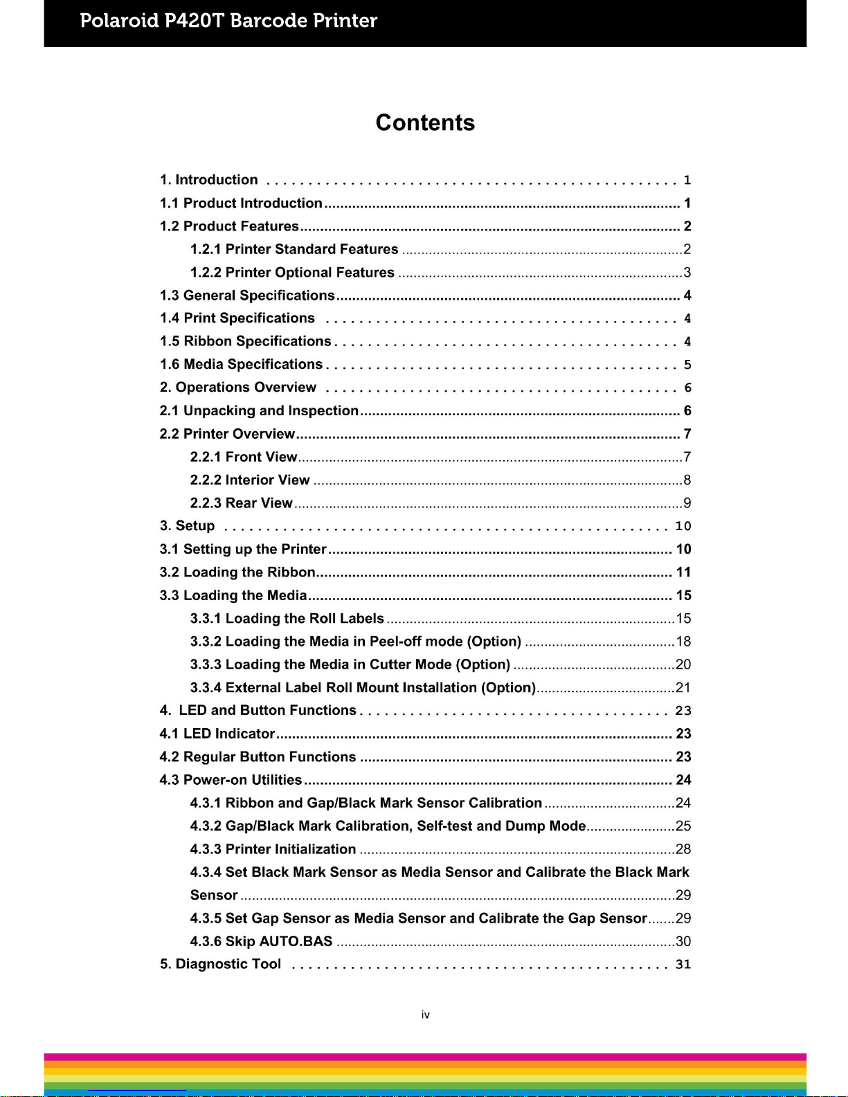
1. Introduction
1.1 Product Introduction
Congratulations on your purchase of a Polaroid P420T Barcode Printer.
This printer features two durable gear-driven motors that are capable of handling large
capacity 300 meter ribbons and large rolls of media within its sleek design. If the 5” interior
label capacity is not enough, simply add an external media roll mount and it can easily
handle 8.4” OD rolls of labels designed for expensive industrial label printers.
The adjustablesensor design accepts wide range of label media.Most of the frequently
used barcodeformats are included. Fonts and barcodes can be printed in any one of the
four directions.
This series of printer is built with the high quality, high performance MONOTYPE IMAGING
®
True Type font engine and one CG Triumvirate Bold Condensed smooth font. With flexible
firmware design, you may download any True Type Font to the printer’s memory. Other than
the scalable font, the printer also offers a choice of five different sizes of alphanumeric
bitmap font, OCR-A and OCR-B fonts. With its rich features, the P420T is the most costeffective and high performance printer in itsclass!
To print label formats, please refer to the instructions provided with your labeling software;
if you need to write custom programs, please refer to the programming manual that can be
found in the CD-ROM.
Applications
o Manufacturing & Warehousing
Work inProgress
ItemLabels
Instructionlabels
Agencylabels
o Healthcare
PatientIdentification
Pharmacy
SpecimenIdentification
o Parcel Post
Shipping/ Receiving
Labels
o Small Office/ HomeOffice
o RetailMarking
Pricetags
Shelflabels
Jewelrytags
1
Page 7
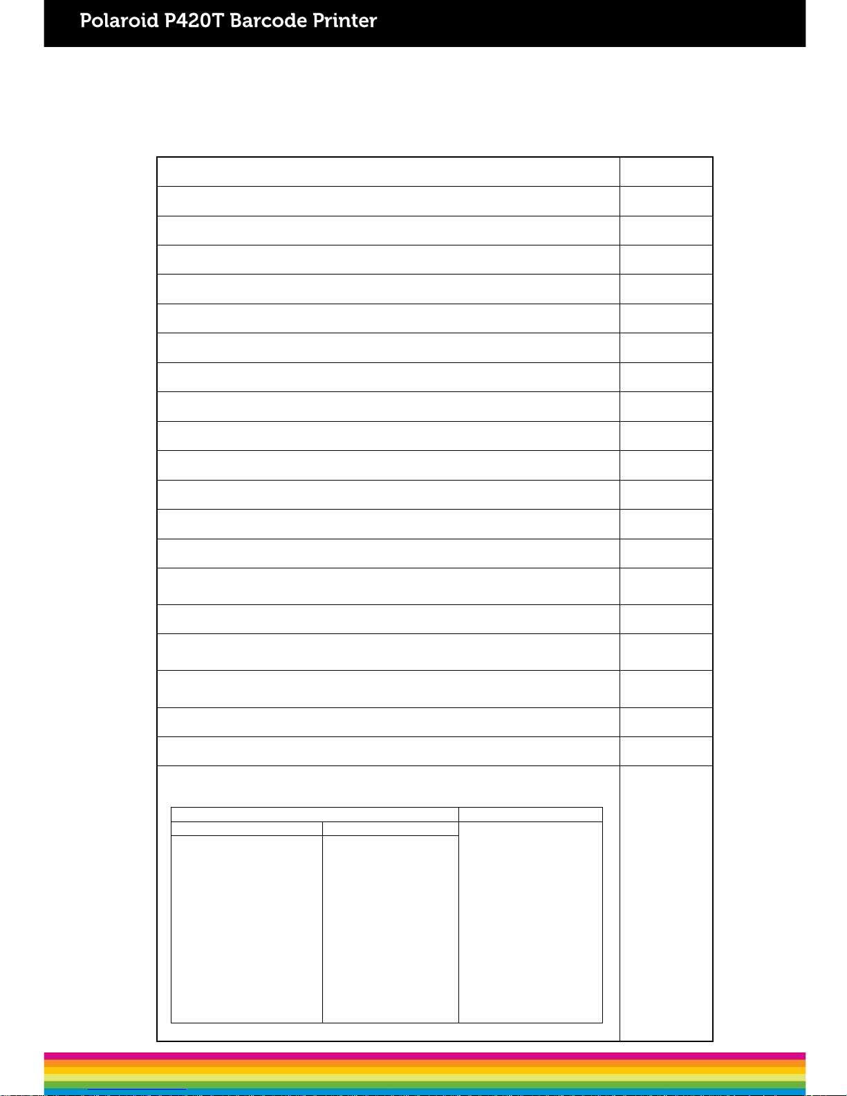
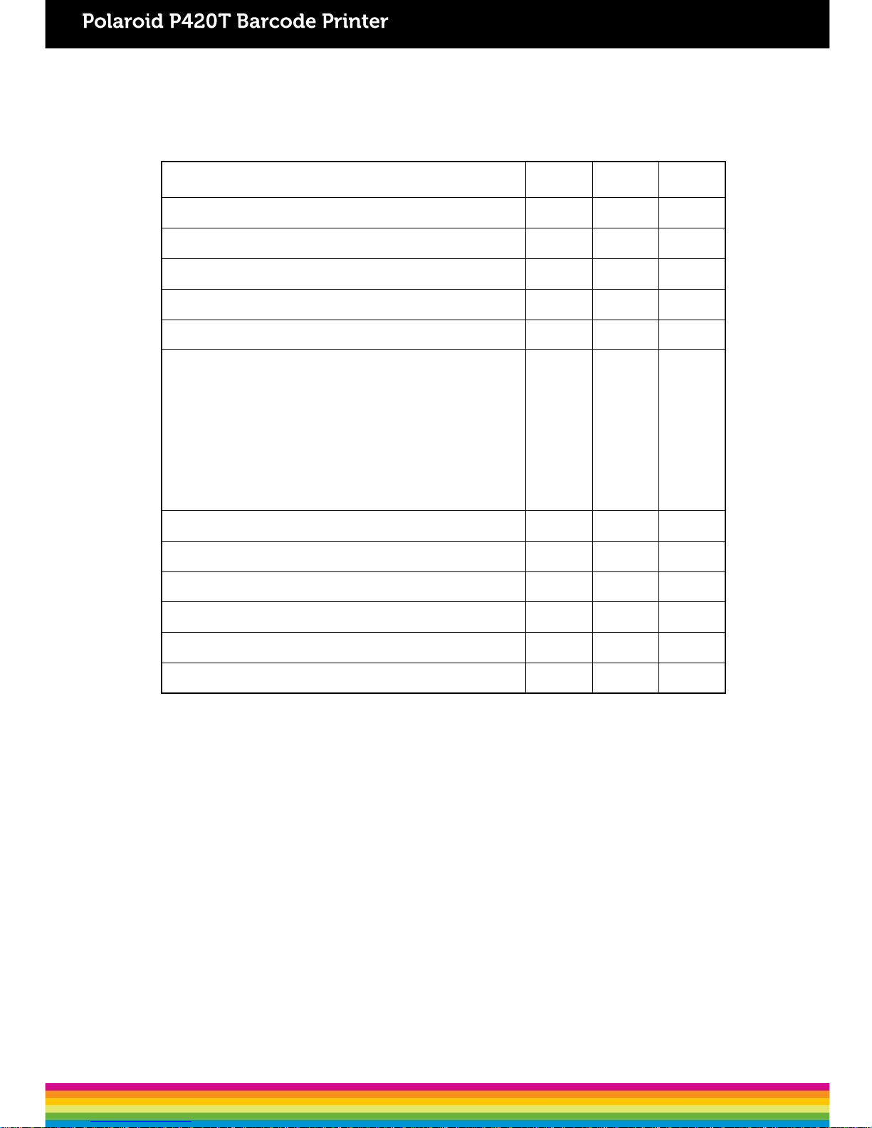
Standard Features
P420T
Thermal transferprinting ○
Direct thermalprinting ○
ABS plasticenclosure ○
Position adjustable gapsensor ○
Position adjustable black marksensor ○
Ribbonsensor ○
Head opensensor ○
USB 2.0 (full speed)interface ○
8 MB SDRAMmemory ○
4 MB FLASHmemory ○
micro SD memorycard reader for memoryexpansion up to 4 GB
○
Real timeclock ○
One power switch, one feed button andLED ○
Standard industry emulations right out of the box including Eltron® and Zebra
®
languagesupport
○
Internal 8 alpha-numeric bitmapfonts ○
Fonts and barcodes can be printed in any one of the four directions (0, 90,180,
270 degree)
○
Internal Monotype Imaging® true type font engine with one
CG Triumvirate Bold Condensed scalablefont
○
Downloadable fonts from PC to printer memory ○
Downloadable firmwareupgrades ○
Text, barcode, graphics/image printing (Please refer to the TSPL/TSPL2
programming manual for supportingcode page)
○
Supported barcode Supportedimage
1D barcode 2D barcode
BITMAP, BMP,
PCX
(Max. 256colors
graphics)
Code39,
Code 93,
Code128UCC,
Code128 subsets
A,B,C, Codabar, Interleaved
2 of 5, EAN-8, EAN-13,
EAN-128,
UPC-A, UPC-E, EAN and
UPC2(5)
digits add-on, MSI, PLESSEY,
POSTNET,
China POST, GS1
DataBar, Code11
PDF-417,
Maxicode,
DataMatrix, QR
code, Aztec,
GS1 DataBar Composite
code
2
1.2 Product Features
1.2.1 Standard Features
The printer offers the following standardfeatures.
Page 8
1.2.2 Optional Features
The printer offers the following optionalfeatures.
Optional Features
User
options
Dealer
options
Factory
options
LCD display (graphic type, 128x64 pixel) with back light
- - ○
Internal Ethernet print server (10/100 Mbps)interface - - ○
Serial RS-232C (2400-115200 bps) interface - - ○
Centronicsinterface - - ○
Peel-offmodule - ○ Guillotine cutter module (Full cut and partial cut)
Paper thickness: 0.06~ 0.19mm, 500,000 cuts
0.20~ 0.25mm, 200,000 cuts
Note:
Except for the linerless cutter, all regular/heavy duty/care
label cutters DO NOT cut on media withglue.
- ○ -
External roll mount with 3” core (8.4 OD) label spindle ○
Extended plate for external rollmount ○
Bluetooth module (RS-232C interface) ○ - KP-200 Plus keyboard displayunit ○ - KU-007 Plus programmable smart keyboard display unit
○ - -
HCS-200 long rangeCCD scanner ○ - -
3
Page 9
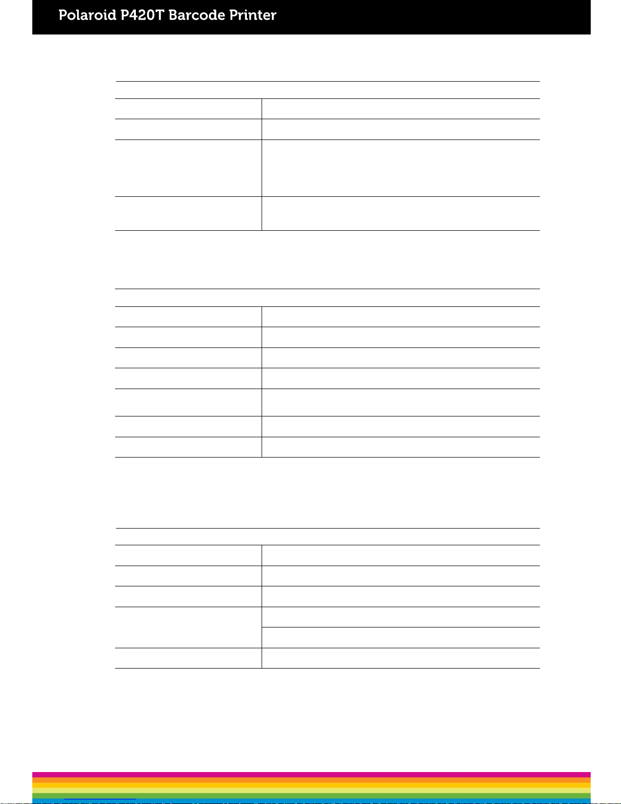
1.3 General Specifications
General Specifications
Physicaldimensions
224 mm
(W) x 186 mm (H) x 294 mm (D)
Weight
2.45
kg
Electrical
External universal
switching powersupply
Input:
AC 100-240V
Output:
DC 24V 2.5A,
60W
Environmentalcondition
Operation:
5 ~ 40˚C (41 ~ 104˚F), 25~85% non-condensing
Storage:
-40 ~ 60 ˚C (-40 ~ 140˚F), 10~90% non-condensing
1.4 Print Specifications
Print Specifications
Print headresolution 203 dots/inch (8 dots/mm)
Printingmethod Thermal transfer and directthermal
Dotsize (width xlength) 0.125 x 0.125mm (1 mm = 8dots)
Printspeed (inches persecond) 5ips
Print speed forpeel
mode & cuttermode
2, 3ips
Max. printwidth 108 mm(4.25”)
Max. printlength 2,794 mm(110”)
1.5 Ribbon Specifications
Ribbon Specifications
Ribbon outsidediameter
Max. 67
mm
Ribbonlength
300
meter
Ribbon core insidediameter
1 inch
(25.4mm)
Ribbonwidth
Max. 110
mm
Min. 40
mm
Ribbon woundtype
Outside
wound
4
Page 10
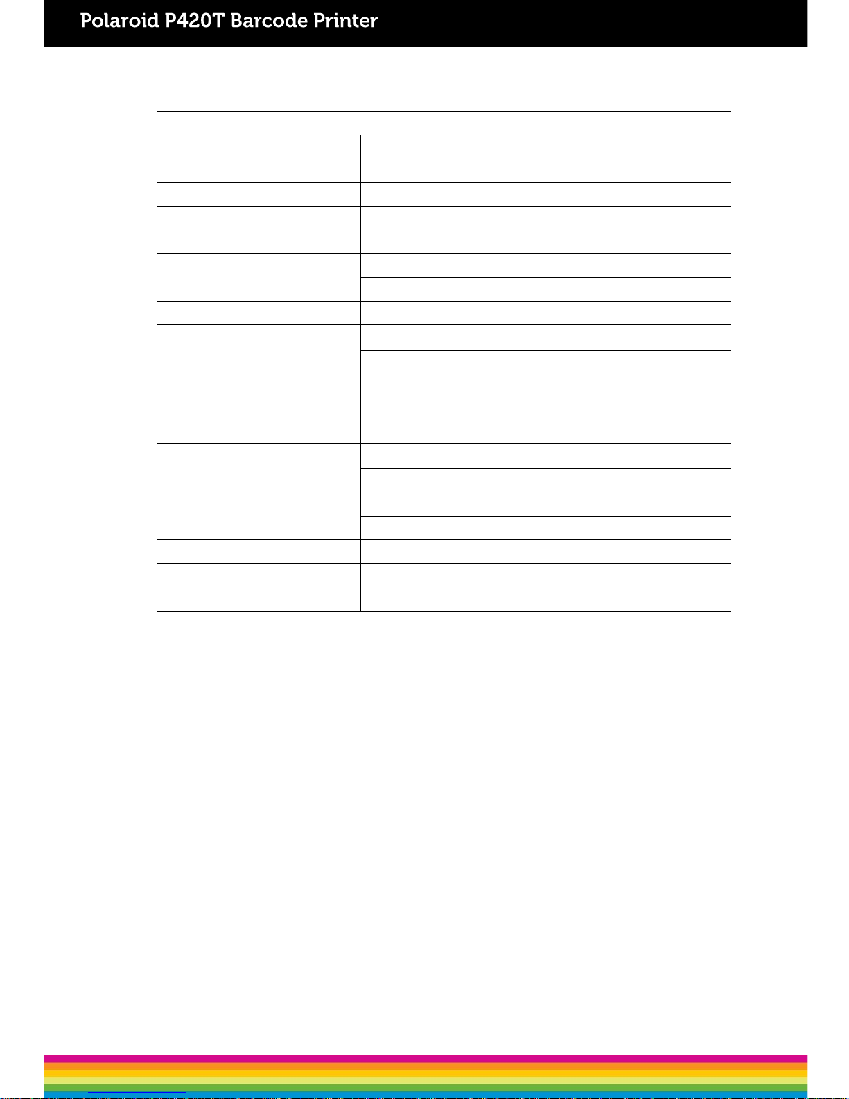
1.6 Media Specifications
Media Specifications
Label rollcapacity
127 mm (5”)
OD
Mediatype Continuous, die-cut, black mark, fan-fold, notch
Media woundtype
Printing
face outside wound & Printing face insidewound
Media width
(label+ liner)
Max. 118 mm
(4.6”)
Min. 25.4 mm
(1.0”)
Media thickness
(label +liner)
Max.
0.254 mm (10mil)
Min. 0.06 mm (2.36
mil)
Media corediameter
25.4 mm~38 mm
(1”~1.5”)
Labellength
10~2,794 mm
(0.39”~110”)
Note:
If your label length
is less than 25.4mm (1”), we
recommend
you to use the perforation at the gap for
easier
tearaway.
Label length
(peeler mode)
Max.
152.4 mm(6”)
Min. 25.4 mm
(1”)
Label length
(cutter mode)
Max.
2,794 mm(110”)
Min. 25.4 mm
(1”)
Gapheight
Min.
2 mm(0.09”)
Black markheight
Min.
2 mm(0.09”)
Black markwidth
Min.
8 mm(0.31”)
5
Page 11
2. Operations Overview
2.1 Unpacking and Inspection
This printer has been specially packaged to be protected from damage during shipping. Upon
receiving, please inspect the packaging and printer carefully. Please retain the packaging
materials, in case you need to re-shipthe printer.
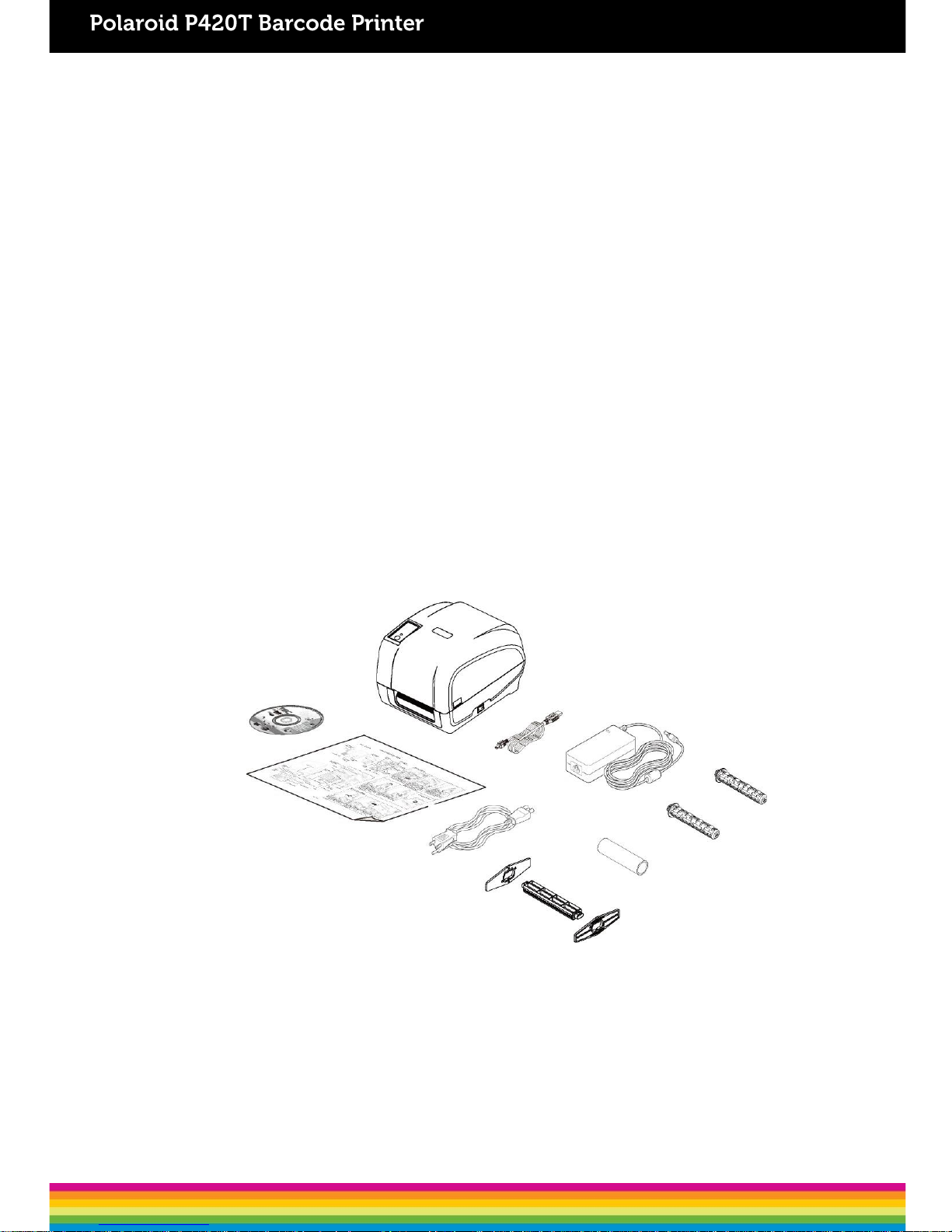
The following items are included in thecarton:
One P420T printer
One Windows labeling software/Windows driver CD
One quick installationguide
One powercord
One auto switching power supply
One USB interfacecable
Two ribbonspindles
One ribbon papercore
One labelspindle
If any items are missing, please contact the Customer Service department of the
reseller/distributor that you purchased the printer from.
6
Page 12
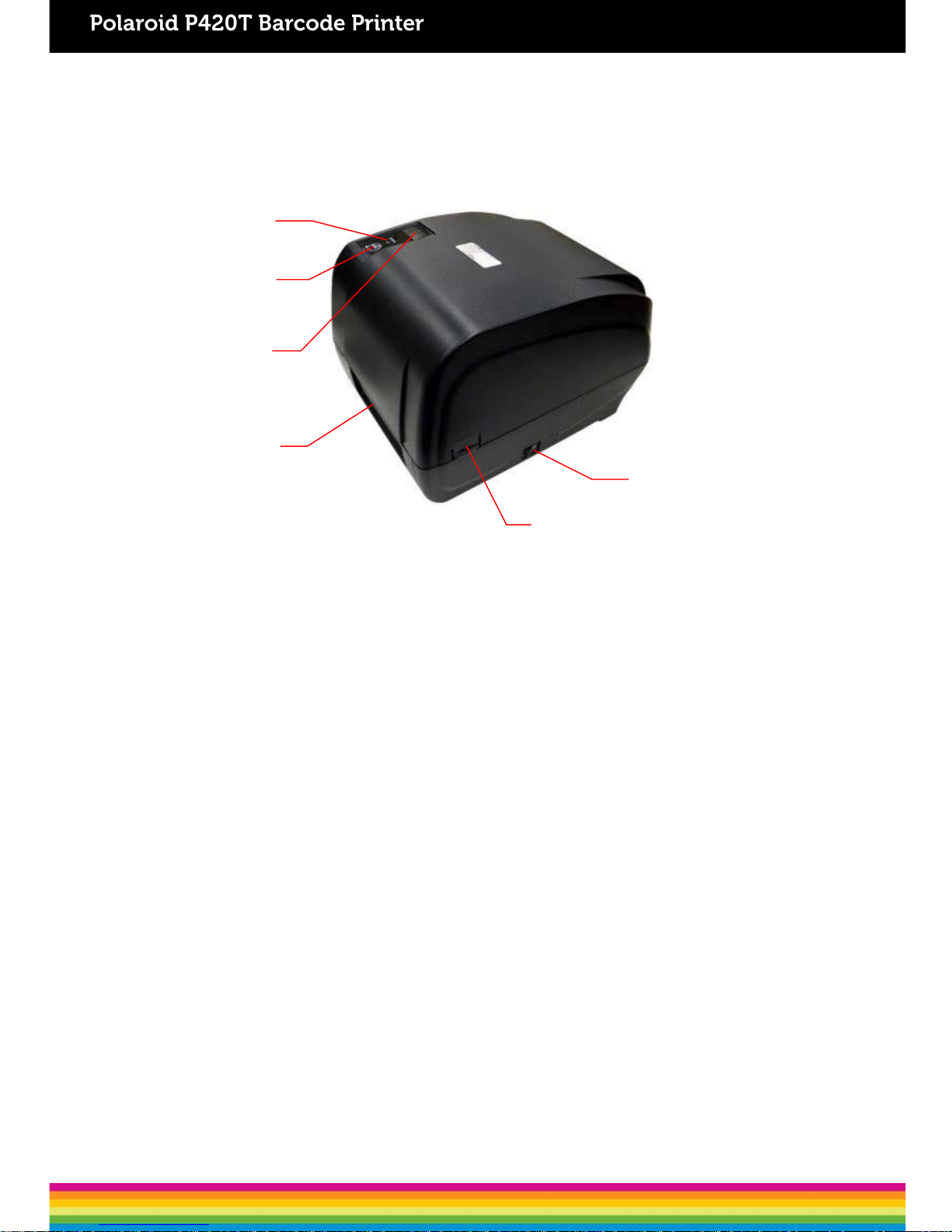
1. LED indicator
2. FEED Button
3. LCD display (Option)
4. Paper exit chute
5. Top cover opentab
6. Power switch
2.2 Printer Overview
2.2.1 FrontView
1
2
3
4
6
5
7
Page 13
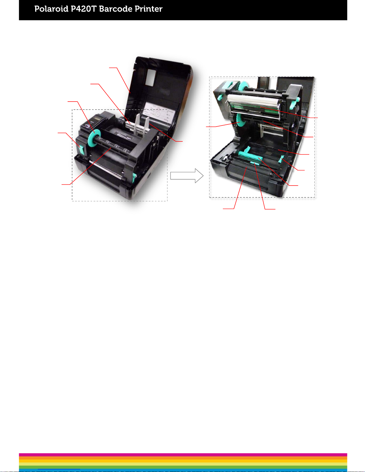
2.2.2 InteriorView
1. Printer topcover
2. Media supplyspindle
3. Ribbon rewindhub
4. Print head releasebutton
5. Ribbon rewindspindle
6. Fixing tab
7. Ribbon supplyhub
8. Platen roller
9. Black mark sensor
10. Gap sensor
11. Media guide
12. Media bar
13. Ribbon supplyspindle
14. Print head
13
9
5
6
4
OPEN
10
12
8
11
1
2
3
14
7
8
Page 14
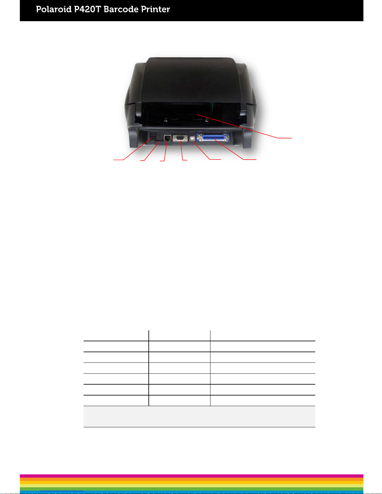
2.2.3 RearView
1. Power jack socket
2. *micro SD cardslot
3. Internal Ethernet interface (Option)
4. RS-232C interface (Option)
5. USB interface (USB 2.0/ Full speedmode)
6. Centronics interface (Option)
7. Rear external label entrancechute
Note:
The above interface is only for reference. Please refer to the product specifications for
the interface options.
* Recommended micro SD cardspecification
SD cardspec
SD
cardcapacity
Approved
SD card manufacturer
V1.0,V1.1
microSD 128
MB
Transcend,
Panasonic
V1.0,V1.1
microSD 256
MB
Transcend,
Panasonic
V1.0,V1.1
microSD 512
MB
Panasonic
V1.0,V1.1
microSD 1
GB
Transcend,
Panasonic
V2.0 SDHC CLASS4
microSD 4
GB
Panasonic
V2.0 SDHC CLASS6
microSD 4
GB
Transcend
- The DOS FAT file system is supported for the SD card.
- Folders/files stored in the SD card should be in the 8.3 filename format.
2
1
6
4
5
3
7
9
Page 15
3. Setup
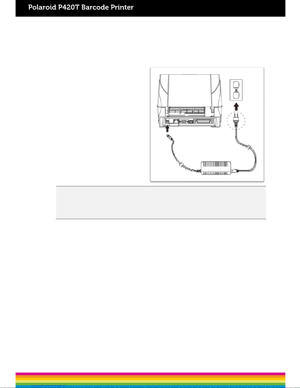
3.1 Setting up the Printer
1. Place the printer on a flat surface.
2. Ensure thatthe power is switched off.
3. Connect the printer to the computer with
the provided USB cable.
4. Insert the power cord into theAC power
cord socket of the printer. Then, insert
the other end of the cord into a properly
grounded AC electrical outlet.
Note:
* The printer power should be turned off before connecting or disconnecting the communications and power cables.
* The above interface is only for reference. Please refer to the product specifications for the interface options.
10
Page 16

3.2 Loading the Ribbon
1. Open the printer‘s top cover by
pulling the latches located on each
side of theprinter.
2. Insert the paper core into the ribbon
rewindspindle.
3. Insert the left side of the spindle into
the ribbon rewind hub first. Then, insert
the right side into the hole at the right
side of ribbonmechanism.
11
Page 17

4. Push the release button to lift up the
print headmechanism.
5. Insert the ribbon into the ribbon spindle.
6. Insert the left side of ribbon supply
spindle into the ribbon supply hub first.
Then, insert the right side of ribbon
supply spindle into the hole at theright
side of ribbonmechanism.
12
Page 18

7
. Lead the ribbonthrough the print
head
and
stick the ribbon’s clear front onto
the
r
ibbon rewind paper core.
8.
Wind up the ribbon rewind hub until
t
he clear front part is thoroughly wound
up
and the black ribbon covers the print
head.
9.
Close the print head mechanismwith
both
hands and ensurethat it is latched
securely
.
13
Page 19

Ribbon loading path
Print head
Ribbon
rewind hub
Ribbon
Paper core
14
Page 20

3.3 Loading the Media
3.3.1 Loading the RollLabels
1. Open the printer‘s top cover by
pulling the latches located on each side
of theprinter.
2. Insert thelabel roll into the media
supply spindle and use the two fixing
tabs to centralise the paper roll onto the
spindle. (If the width of your label is 4",
you can remove the fixing tabsfrom the
supplyspindle.)
3. Place the label roll onto the media
rollmount.
15
15
Page 21

4. Push the release button to lift up the
print head mechanism.
5. Pull the label (printingside faced up),
through the media bar, media sensor and
place the label‘s leading edge onto the
platen roller. Move the media guides to fit
the label.
Gapsensor Black marksensor
Gap sensor
Black mark
sensor
Media guide
Platen roller
Note: The media guide is adjustable. Please ensure that the gap or black mark is
at the location where media gap/black mark will pass through for sensing.
16
Page 22

Note: Please calibrate the gap/ black mark sensor when changing media.
Media loading path
Media
Media bar
Media guide
Gap sensor
Platen roller
Black mark sensor
6.
Close the print head mechanismwith
both hands and ensure
that it is latched
securely.
1
2
7
. Use “Diagnostic Tool” to set the
media
sensor type and
calibratethe selected
sensor. (Start
the “Diagnostic tool”
Select
the “Printer Configuration” tab
Click
the “Calibrate Sensor” button )
Please refer
to section5.3.
Path for outside wound
Path for inside wound
17
Page 23

3.3.2 Loading the Media in Peel-off mode (Option)
1. Refer to Chapter 3.3.1 to load the
label roll. Use “Diagnostic Tool” to set
the media sensor type and calibrate the
selectedsensor.
2. Pull the label through thefront of the
printer and peel some labels off theliner.
3. Open the peel-off cover. Feed the
liner into peel-off coverslot.
Liner
Label
Liner
Peel-off
cover slot
18
Page 24

4. Close the peel-off cover.Use the
DiagTool to set the peel-off mode by
selecting “PEEL” option for Post-Print
Action setting. Then,click “Set” button
to enable the peel-off mode.
6. Press the FEED button to test.
Note:
Please calibrate the gap/black mark sensor when changing media.
Liner
5. Close the printhead mechanism
and printer cover. Printer is ready for
peel-offmode.
Liner
Label
19
Page 25

3.3.3 Loading the Media in Cutter Mode (Option)
Note:
Please calibrate the gap/black mark sensor when changing media.
1. Refer
to Chapter 3.3.1 to load the
label roll.
2
. Pull the label through thecutter
paper
opening.
3.
Close the print headmechanism and
printer
cover. Use theDiagTool to set
the
printer
for cutter mode by selecting
“CUTTER” option
for Post-Print Action
setting
then click “Set” button to enable
the
cutter mode. Press
the FEED button
to
test.
20
Page 26

3.3.4 External Label Roll Mount Installation (Option)
Extended
External label
plate
rollmount
1.
Installthe extended plate onto the
external
label rollmount with 2 screws.
2.
Attach the extended plate onthe
bottom
of the printer. If you
purchase the
external label roll
mount only, you’d just
need to put
it on the rear of printer.
3.
Insert a 3” (or 1”) label spindle intoa
paper
roll. And install it ontothe external
paper roll
mount.
21
1” label
spindle
3” label
spindle
Page 27

4. Feed the media through the rear
external label entrancechute.
5. Refer to chapter 3.3.1 to install the
label. Use “Diagnostic Tool” to set
the media sensor type and calibrate
the selectedsensor.
Note:
Please calibrate the gap/black mark sensor when changing media.
22
Page 28

4. LED and Button Functions
This printer has one button and one three-color LED indicator. By indicating the LED with
different colors and pressing the button, printer can feed labels, pause the printing job, select
and calibrate the media sensor, print printer self-test report and reset printer to default
settings (initialization). Please refer to below table for the different functions.
4.1 LED Indicator
LEDColor Description
Green/Solid
This indicatesthat the power is on and the device is ready to
be used.
Green/Flash
This indicatesthat the system is downloading data from the
PCto the printer’s memory, or the printer isbeing paused.
Amber This indicatesthat the system is clearing data from printer.
Red /Solid This indicates that the printer head is open/ cutter error.
Red /Flash
This indicatesa printing error, such as printer head is open,
no paper, paper jam, no ribbon, or memory error etc.
4.2 Regular Button Functions
1. Feedlabels
When the printer is at ready mode (Green/Solid), press the button to feed one label to the
beginningof next.
2. Pause the printingjob
When the printer is at printing mode, press the button to pause a print job. When the printer is
paused, the LED will be blink in green. Press the button again to continue the printing job.
23
Page 29

4.3.1 Ribbon and Gap/Black Mark Sensor Calibration
Gap/black mark sensor sensitivity calibration should be performed for the following conditions:
1. A brand new printer
2. Change label stock
3. Printer initialization
Please follow the steps below to calibrate the ribbon and gap/black mark sensor:
1. Switch off the printer
2. Press the button while you switch on the printer
3. Release the button when LEDis red and blinking.
4.3 Power-on Utilities
There are six power-on utilities to set up and test the printer. These utilities are activated by
pressing the FEED buttonand then, switching on the printer simultaneously and releasingthe
button at different color ofLED.
Please follow the steps below for different power-on utilities:
1. Switch off the printer
2. Press the button while you switchon the printer
3. Release the button when LED indicates accordingly
Power onutilities The LED color will change as follows:
LEDcolor
Functions
Amber
Red
(5
blinks)
Amber
(5blinks)
Green
(5
blinks)
Green/Amber
(5blinks)
Red/Amber
(5blinks)
Solidgreen
1. Ribbon sensor calibration and gap /
black mark sensorcalibration
Release
2. Gap / black mark sensor calibration,
Self-test and enter dumpmode
Release
3. Printerinitialization
Release
4. Set black mark sensor as media
sensor and calibrate the black mark
sensor
Release
5. Set gap sensor as media sensorand
calibrate the gapsensor
Release
6. SkipAUTO.BAS
Release
24
Page 30

It will calibrate the ribbon sensor and gap/black mark sensor sensitivity.
The LED color will change according to the following order:
Amber red (5 blinks) amber (5 blinks) green (5 blinks) green/amber (5 blinks)
red/amber (5 blinks) solid green
Note:
Please select gap or black mark sensor by sending GAP or BLINE command to printer prior to
calibrating the sensor.For more information about GAP and BLINE command, please refer to
TSPL2 programming manual.
4.3.2 Gap/Black Mark Calibration, Self-test and Dump Mode
While calibratingthe gap/black mark sensor, printer will measure the label‘s length, print the
internal configuration (self-test) on label and then, enter the dump mode. To calibrate gap or
black mark sensor, it depends on the sensor setting from the last print job.
Please follow the steps below to calibrate thesensor:
1. Switch off the printer
2. Press the button while you switch on the printer
3. Release the button when LED becomes amber and blinking.
The LED color will change according to the following order:
Amber red (5 blinks) amber (5 blinks) green (5 blinks) green/amber (5 blinks)
red/amber (5 blinks) solid green
4. Printer will calibrate the sensor, measure the label‘s length, print internal settings, andthen
enter the dump mode.
Note:
Please select gap or black mark sensor by Diagnostic Tool or by GAP or BLINE command prior to
calibrate thesensor. For more information about GAP and BLINE command, please refer to TSPL2
programming manual.
25
Page 31

Self-test
Printer will print its configuration after gap/black mark sensor calibration. Self-test printout
can be used to check if there is any dot damage on the heater element, printer
configurations and available memory space.
Self-test printout
Printer model name & Main board firmware version
Printer serialnumber
Printedmileage
Main board firmware checksum
Serial portsetting
Code page
Country code
Print speed
Printdarkness
Label size (width, height)
Black mark or gap size (vertical gap, offset)
Sensorsensitivity
Ethernet settings information(option)
File managementinformation
Print head testpattern
Self-test printout (with printer firmware V7.0 and later version)
Modelname
F/Wversion
Firmwarechecksum
Printer S/N
Configurationfile
Systemdate
Systemtime
Printed mileage (meter)
Cuttingcounter
26
Page 32

Print speed (inch/sec)
Printdarkness
Label size (inch)
Gap distance(inch)
Gap/black mark sensorintension
Code page
Countrycode
ZPL setting information
Printdarkness
Print speed(inch/sec)
Label size
Control prefix
Format prefix
Delimiterprefix
Printer power up motion
Printer head close motion
Note:
ZPL is emulating for Zebra
®
language.
RS232 serialport
configuration
Numbers of download files
Total & available memory
space
Print head check pattern
27
Page 33

4.3.3 PrinterInitialization
Printer initialization is used to clear DRAM and restore its settings to default. The only exception
is ribbon sensitivity, which will not be restored to default.
Printer initialization is activated by the following procedures.
1. Switch off the printer
2. Press the button while you switch on the printer
3. Release the button when LED turns green after 5 amber blinks.
The LED color will be changed asfollowing:
Amber red (5 blinks) amber (5 blinks) green (5 blinks) green/amber (5 blinks)
red/amber (5 blinks) solid green
Dumpmode
Printer will enter dump mode after printing its configuration. In the dump mode, all characters
will be printed in 2 columns as follows. The left side characters are received from your system
and the right side data are the corresponding hexadecimal value of the characters. It allows
users or engineers to verify and debug theprogram.
Note:
1. Dump mode requires 4” wide paper width.
2. Turn off / on the power to resume printer for normal printing.
ASCIIData
Hex decimal data related to left
column of ASCIIdata
28
Page 34

4.3.4 Set Black Mark Sensor as Media Sensor and Calibrate the Black Mark Sensor
Please follow the steps asbelow.
1. Switch off the printer
2. Press the button while you switch on the printer
3. Release the button when LED turns green/amber after 5 green blinks. (Any green/amber will
do during the 5blinks).
The LED color will change according to the following order:
Amber red (5 blinks) amber (5 blinks) green (5 blinks) green/amber (5 blinks)
red/amber (5 blinks) solid green
4.3.5 Set Gap Sensor as Media Sensor and Calibrate the Gap Sensor
Please follow the steps asbelow.
1. Switch off the printer
2. Press the button while you switch on the printer
Printer configuration will be restored to defaults as below after initialization.
Parameter Default setting
Speed
101.6
mm/sec (4 ips)(203DPI)
76
mm/sec (3 ips)(300DPI)
Density
8
Label
Width
4” (101.5
mm)
Label
Height
4” (101.5
mm)
Sensor
Type
Gap
sensor
Gap
Setting
0.12”
(3.0mm)
Print
Direction
0
Reference
Point
0,0
(upper leftcorner)
Offset
0
Tear
Mode
On
Peel
offMode
Off
Cutter
Mode
Off
Serial Port
Settings
9600
bps, none parity, 8 data bits, 1 stop bit
Code
Page
850
Country
Code
001
Clear
FlashMemory
No
IP
Address
DHCP
29
Page 35

3. Release the button when LED turns red/amber after 5 green/amber blinks.
The LED color will change according to the following order:
Amber red (5 blinks) amber(5 blinks) green(5 blinks) green/amber(5 blinks)
red/amber (5 blinks) solid green
4.3.6 SkipAUTO.BAS
TSPL2 programming language allows user to download an auto execution file to flash memory.
Printer will run the AUTO.BAS program immediately when switching on the printer. The
AUTO.BAS program can be interrupted without running the program by the power-on utility.
Please follow the procedures below to skip an AUTO.BAS program.
1. Switch off the printer
2. Press the FEED button while you switch on the printer
3. Release the FEED button when LED becomes solid green.
The LED color will change according to the following order:
Amber red (5 blinks) amber(5 blinks) green(5 blinks) green/amber(5 blinks)
red/amber (5 blinks) solid green
4. Printer will be interrupted to run the AUTO.BAS program.
30
Page 36

5. Diagnostic Tool
This Diagnostic Utility is an integrated tool incorporating features that enable you to explore a
printer’s settings/status; change a printer’s settings; download graphics, fonts and firmware;
create a printer bitmap font; and send additional commands to a printer. With this powerful
tool, you can review printer status and settings in an instant, which makes it much easier to
troubleshoot problems or issues.
5.1 Start the Diagnostic Tool
1. Double click on the Diagnostic tool icon to start thesoftware.
2. There are four features (Printer Configuration, File Manager, Bitmap Font Manager,
Command Tool) included in the Diagnostic utility.
Printerfunctions
Featurestab
Interface
PrinterStatus
Printersetup
31
Page 37

5.2 Printer Function
1. Select the PC‘s interface connected to the printer.
2. Click the “Printer Function” button to setup.
3. The detailed functions in the Printer Function Group are listed asbelow.
Function Description
Calibrate
Sensor
Calibrate
the
sensor specified in the Printer Setup
group
media sensorfield
Ethernet
Setup
Setup the
IP address, subnet mask, gateway for
the
on boardEthernet
RTC
Setup
Synchronize printer
Real Time Clock with PC
Print
TestPage
Print a
testpage
Reset
Printer
Reboot
printer
Factory
Default
Initialize the printer and restore the settings
to
factory
default. (Please refer section4.3.3)
Dump
Text
To
activate the printer dumpmode.
Ignore
AUTO.BAS
Ignore the
downloaded AUTO.BAS program
Configuration
Page
Print printer configuration
(Please refer section
4.3.2)
Password
Setup
Set
the password to protect the settings
For more information about Diagnostic Tool, please refer to the diagnostic utility quick start
guide in the CD disk \ Utilities directory.
2
1
The
default interface settingis
USB. If
printer is connected via
USB
interface, no changes is
needed
32
Page 38

5.3 Calibrating Media Sensor by Diagnostic Tool
5.3.1 Auto Calibration
1. Make sure the media is install ready and print head mechanism is closed. (Please refer to
section3.3.)
Note: The media sensor position is adjustable. Please ensure that the gap (▽) or
black mark is at the location where media gap/black mark will pass through for
sensing.
Gapsensor Black marksensor
2. Switch on the printer
3. Open Diagnostic tool and set the interface. (The default setting is USB.)
4. Click the “Calibrate Sensor” button.
5. Select the media type and click the “Calibrate” button.
1
2
2
1
The
default interface settingis
USB interface. If USB
interface
is
connected with printer,no
other settings need to
be
changed
in the interfacefield.
33
33
Page 39

5.4 Setting Ethernet by Diagnostic Utility (Option)
The Diagnostic Utility is enclosed in the CD disk \Utilities directory. Users can use Diagnostic Tool to
set up the Ethernet by RS-232, USB and Ethernet interfaces. The following contents will guide users
on how to configure the Ethernetsettings via these three interfaces.
5.4.1 Using USB interface to setup Ethernetinterface
1. Connect the USB cable between the computer and the printer.
2. Switch on the printer.
3. Start the Diagnostic Utility by double clicking onthe
icon.
4. The Diagnostic Utility defaultinterface setting is USB. If USBinterface is connected with
printer, no other settings need to be changed in the interface field.
5. Click on the “Ethernet Setup” button from “Printer Function” group in Printer Configuration
tab to setup the IP address, subnet mask and gateway for the on board Ethernet.
34
Page 40

5.4.2 Using RS-232 interface to setup Ethernet interface
1. Connect the computer to the printer with a RS-232 cable.
2. Switch on the printer.
3. Start the Diagnostic Utility by double-clicking on the
icon.
4. Select “COM” as interface then click on the “Setup” button to setup the serial port baud rate,
parity check, data bits, stop bit and flow controlparameters.
5. Click on the “Ethernet Setup” button from printer function of Printer Configuration tab,to
setup the IP address, subnet mask and the gateway for the on board Ethernet.
35
Page 41

5.4.3 Using Ethernet interface to setup Ethernet interface
1. Connect the computer and the printer to the LAN.
2. Switch on the printer.
3. Start the Diagnostic Utility by double-clicking on the
icon.
4. Select “Ethernet” as the interface then click on the “Setup” button to setup the IP address,
subnet mask and gateway for the on board Ethernet.
5. Click the “Discover Device” button to explore the printers that exist on the network.
6. Select the printer in the left side of listed printers, the correspondent IP address will be
shown in the right side “IP address/Printer Name” field.
7. Click “Change IP Address” to configure the IP address obtained by DHCP or static.
The default IP address is obtained by DHCP. To change the setting to static IP address,
click “Static IP” radio button then enter the IP address, subnet mask and gateway. Click “Set
IP” to take effect thesettings.
36
Page 42

Users can also change the “Printer Name” by another model name in this field, then click
“Set Printer Name” to take effect thischange.
Note: After clicking the “Set Printer Name” or “Set IP” button, printer will reset for the
settings to take effect.
8. Click “Exit” button to exit the Ethernet interface setup and go back to Diagnostic Tool main
screen.
Factory Defaultbutton
This function will reset the IP, subnet mask, gateway parameters obtained by DHCP and
reset the printername.
Web setupbutton
Except to use the Diagnostic Utility to setup the printer, you can also explore and configure
the printer settings and status or update the firmware with the IE or Firefox web browser.
This feature provides a user friendly setup interface and the capability to manage the printer
remotely over anetwork.
37
Page 43

6. Troubleshooting
6.1 Common Problems
The following guide lists out the most common problems that you may encounter when using this
barcode printer. If the printer still does not function after applying the suggested solutions, please
contact the Customer Service Department of the reseller or distributor that you purchased the printer
from, for assistance.
Problem
Possible Cause
Suggested
Solution
Power indicator
doesnot
illuminate
*
The power cord isnot
properlyconnected.
* Plug in the power cord to printer and outlet.
* Switch on the printer.
- The printer statusfrom
DiagTool indicates
“Head Open”.
- The LCD shows“Carriage
Open”.
*
The printer coveris open.
* Please close the print
cover.
- The printer statusfrom
DiagTool indicates “Ribbon
End Err.” Or “
Ribbon Encoder
Err.”
- The LCD shows “No Ribbon”.
* Running out of ribbon.
* The ribbon isinstalled
incorrectly.
* Installa new ribbonroll.
* Please refer to the steps on section 3.2 to
re-install theribbon.
- The printer statusfrom
DiagTool shows “Out
of Paper”.
- The LCD shows “NoPaper”.
* Running out oflabel.
* The label isinstalled
incorrectly.
* Gap/black mark sensor is not
calibrated.
* Install a new label roll.
* Please refer to the steps on section 3.3 to
re-install the labelroll.
* Calibrate the gap/black mark sensor.
- The printer status from
DiagTool shows “Paper Jam”.
- The LCD shows “PaperJam”.
* Gap/black mark sensor is not
setproperly.
* Make sure label size is set
properly.
* Labels may be stuckinside
the printermechanism.
* Calibrate the gap/black mark sensor.
* Set label sizecorrectly.
-
The LCD shows “Take Label”.* Peel-off function is enabled.
* If the peel-off module is installed, please
remove thelabel.
* If there is no peel-off module in front of the
printer, please switch off the printer and
installit.
* Check if the connector is plugging
correctly.
38
Page 44

Problem
Possible Cause
Suggested
Solution
Not
Printing
* Cable is not connected to
serial or USB interface or
parallelport correctly.
* The serial port cablepin
configuration is not pin to pin
connected.
* Re-connect cable to interface.
* If using serialcable,
- Please replace the cable with pin to pin
connected.
- Check the baud rate setting. The default baud
rate setting of printer is 9600,n,8,1.
* If using the Ethernet cable,
- Check if the Ethernet RJ-45 connector
green LED is lit on.
- Check if the Ethernet RJ-45 connector
amber LED is blinking.
- Check if the printer gets the IP address when
using DHCPmode.
- Check if the IP address is correct when using
the static IP address.
- Wait a few seconds let the printer get the
communication with the server then check the
IP
address setting again.
* Change a newcable.
* Ribbon and media are not compatible.
* Verify the ribbon-inkedside.
* Reload the ribbonagain.
* Clean the printhead.
* The print density setting isincorrect.
* Print head’s harness connector is not well
connected with printheat. Turn off the printer and
plug the connector again.
* Check your program if there is a command PRINT
at the end of the file and theremust have CRLF at
the end of each command line.
Memory
full
( FLASH / DRAM
)
*
The space of FLASH/DRAM
isfull.
* Delete unused files in the FLASH/DRAM.
* The max. numbers of DRAM is 256 files.
* The max. user addressable memoryspace of
DRAM is256KB.
* The max. numbers of file of FLASH is 256 files.
* The max. user addressable memoryspace of
FLASH is 2560KB.
microSD card
is unableto use
* microSD card isdamaged.
* microSD card doesn’t insert
correctly.
* Use the non-approved
microSD cardmanufacturer.
* Use the supported capacity microSDcard.
* Insert the microSD cardagain.
* The supported microSD card spec and the
approved microSD card manufacturers, please
refer to section2.2.3.
Poor Print
Quality
* Ribbon and media is loaded
incorrectly
* Dust or adhesive
accumulation on the print
head.
* Print density is notset
properly.
* Printhead element
is damaged.
* Ribbon and media are
incompatible.
* The printhead pressure is not
setproperly.
* Reload the supply.
* Clean the printhead.
* Clean the platenroller.
* Adjust the print density and print speed.
* Run printer self-test and check the print head
test pattern if there is dot missing in thepattern.
* Change proper ribbon or proper label
media.
* The print head mechanism does not latch the
print headproperly.
39
Page 45

Problem
Possible Cause
Suggested
Solution
Cutter is not
working
* The connector isloose.
* Cutterjam.
* Cutter PCB isdamaged.
* Plug in the connect cable correctly.
* Remove thelabel.
* Make sure the thickness of label is less
than 0.19mm.
* Replace a cutter driver ICboard.
Skip
labels whenprinting
* Label size is not specified
properly.
* Sensor sensitivity is not set
properly.
* The media sensor is covered
withdust.
* Check if label size is setup correctly.
* Calibrate the sensor by Auto Gap or
Manual Gapoptions.
* Clear the GAP/Black mark sensor by
blower.
The printing position of small
label isincorrect
* Media sensor sensitivity isnot
setproperly.
* Label size isincorrect.
* The parameter Shift Y in the
LCD menu isincorrect.
* The vertical offset setting in
the driver is incorrect.
* Calibrate the sensor sensitivity again.
* Set the correct label size and gap size.
* If using the software BarTender, pleaseset
the vertical offset in the driver.
Missing printing on the left
or
right side of
label
*
Wrong label sizesetup.
* Set the correct label
size.
RTC
time is incorrectwhen
reboot the
printer
*
The battery has run down.
* Check if there is a
battery on the main
board.
Wrinkle
problem
* Ribbon installation
is incorrect.
* Media installation is incorrect.
* Print density isincorrect.
* Media feeding isincorrect.
* Please set the suitable density to have
good print quality.
* Make sure the label guide touch the edge of
the mediaguide.
Gray
line on the blanklabel
* The print head isdirty.
* The platen roller is dirty.
* Clean the printhead.
* Clean the platenroller.
Irregular
printing
* The printer is in Hex Dump
mode.
* The RS-232 settingis
incorrect.
* Turn off and on the printer to skip the
dumpmode.
* Re-set the Rs-232setting.
40
Page 46

7. Maintenance
This section provides routine cleaning and maintenance procedures.
1. Please use one of following material to clean theprinter.
Cottonswab
Lint-freecloth
Vacuum / Blowerbrush
100%ethanol
2. The cleaning process is described asfollowing,
PrinterPart Method Interval
PrintHead
1.
Always switchoff the printer
before cleaning the printhead.
2.
Allow the print head to cool forat
least oneminute.
3.
Use a cotton swab and 100%
ethanol to clean the print head
surface.
Clean
the print head when changing anew
label
roll.
PlatenRoller
1.
Switch off the printer.
2.
Rotate the platen roller and wipe it
thoroughly with 100% ethanol and a
cotton swab, or lint-freecloth.
Clean
the platen roller when changing a
new label
roll
Tear Bar/PeelBar
Use
the lint-free cloth with 100%
ethanol to
wipeit.
As
needed
Sensor
Compressed
air orvacuum
Monthly
Exterior
Wipe it
with water-dampenedcloth
As
needed
Interior
Brush or
vacuum
As
needed
Note:
Do not touch printer head by hand. If you touch it, please use ethanol to clean it.
Please use 100% Ethenol. DO NOT use medical alcohol, which may damage the printerhead.
Regularly clean the print head and supply sensorsonce you change to a new ribbon, in order
to maintainthe printer‘s performance and extend the printer‘s life.
41
Page 47

 Loading...