

Polaroid ID-3000 Repair Manual
Repair Manual
ID-3000 Digital Security
and Identification System
April 1994
Americas Business Center
Technical Services
201 Burlington Road
Bedford MA 01730
TEL: 1.781.386.5309
FAX: 1.781.386.5988

This page intentionally blank.

Polaroid ID3000 Service Manual Contents
ID-3000 SYSTEM SERVICE MANUAL
CONTENTS
SECTION 1 GENERAL DESCRIPTION OF SYSTEM
SECTION 2 SYSTEM INSTALLATION
SECTION 3 DIAGNOSTICS/TROUBLESHOOTING
SECTION 4 CALIBRATION PROCEDURES
SECTION 5 PARTS REPLACEMENT
APPENDIX

This page intentionally blank.

Polaroid ID3000 Service Manual Description
SECTION 1 - DESCRIPTION
Contents
Page
System Overview 1-3
System Hardware Components 1-5
System Functions: 1-7
Make a new ID card 1-7
Capture Portrait & Signature 1-8
Enter Applicant Data Only 1-8
Verify Applicant 1-8
Reissue ID card 1-8
Adjust System 1-8
Workstation Computer 1-9
Board Descriptions 1-10
Computer Keyboard 1-10
Color Monitor 1-11
Color Portrait Camera 1-12
Portrait Lighting Strobe Unit 1-12
Signature Scanner 1-13
Color Film Recorder (CFR) & Camera Back 1-14
Thermal Color Printer 1-15
Digital Scanner 1-16
Die Cutters 1-17
Laminators 1-17
Surge Protector/Power Strip 1-18
1-1

Polaroid ID3000 Service Manual Description
This page intentionally blank.
1-2

Polaroid ID3000 Service Manual Description
SECTION 1 — ID-3000 SYSTEM DESCRIPTION
ID-3000 System Overview
The Polaroid ID-3000 System (Figure 1-1) produces highly secure, color-portrait photoidentification cards, and electronically stores text, portraits and other ID images for each
applicant. ID cards consist of several elements, and may include: information about the applicant, his or her portrait, signature, fingerprints and card format elements.
There are presently two versions of the ID-3000 System, differing only in the output device
used to produce the photo ID card. The ID-3000F System has a CI-5000 Color Film Recorder which produces the ID card on Polaroid instant color film. The ID-3000T System has
a TX-1500 Color Thermal Printer which produces a full- color ID card on heat-sensitive
paper.
The system can operate as part of a network (LAN, WAN, Mainframe), linked to a host
computer, or it can function as a stand-alone system. The system electronically captures the
applicant’s video portrait and signature and stores them in memory, along with text data about
the applicant and identification card formatting data. The data may be stored in either a host
computer or in a local disk drive in the System PC.
After information about the applicant has been stored, it can be rapidly retrieved and displayed on the system monitors, for verification, updating or adding missing information.
System software combines the applicant data and portrait with specific codes, colors or
designs, to produce a custom ID card.
The ID3000 System can be integrated with the CS500i Polaroid Color Scanner, Magstripe
Encoder, Bar Code Label Printers, and Still Video Camera systems.
1-3
Polaroid ID3000 Service Manual Description
Note: Leave 12" or more between the CI-5000 Color Film Recorder
and the VGA Monitor, to prevent electrical interference.
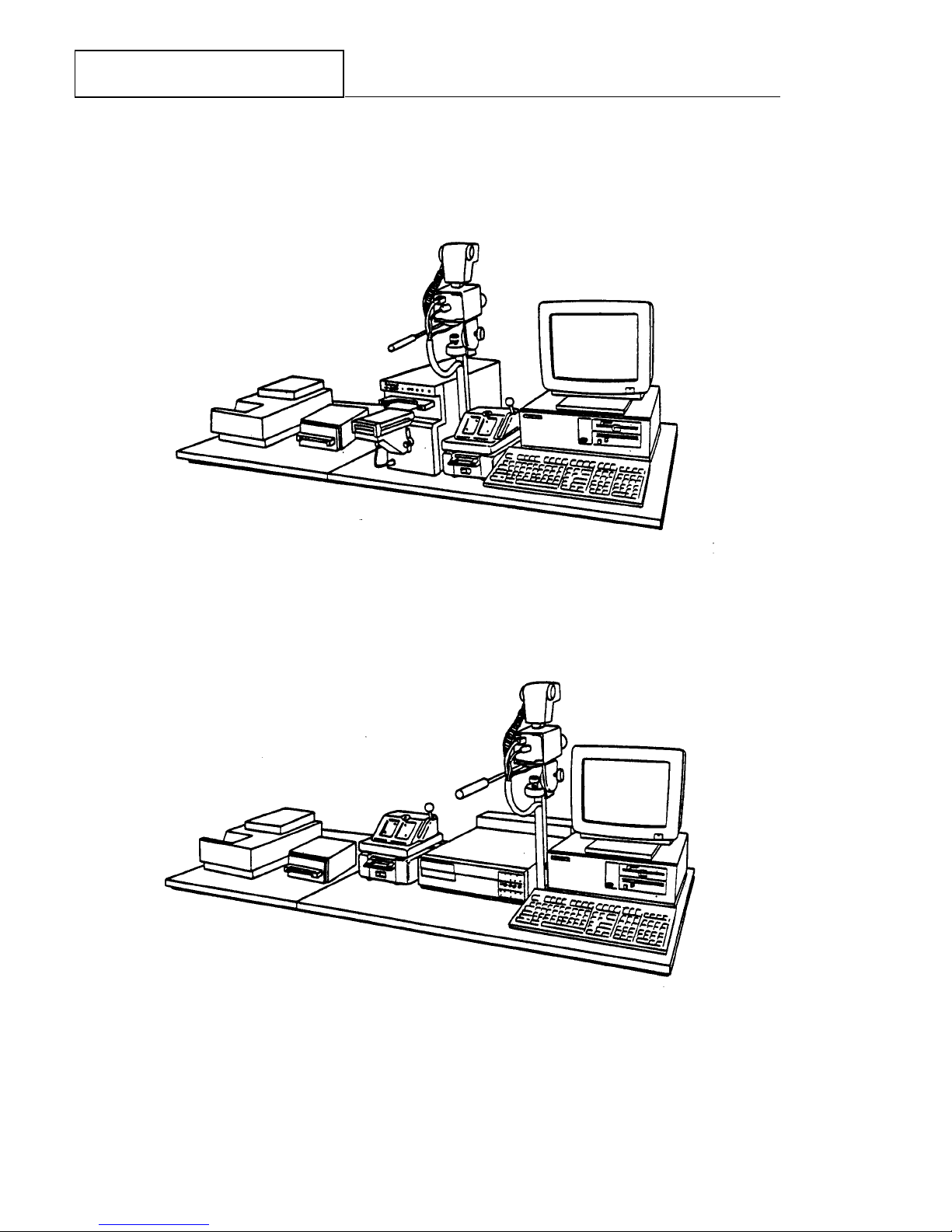
ID-3000F with CI-5000 Film Recorder, CS500i Color Scanner (optional)
and Signature Scanner (optional)
ID-3000T with TX-1500 Thermal Recorder, CS500i Color Scanner (optional)
and Signature Scanner (optional)
Figure 1-1 ID-3000F and 3000T System configurations
1-4
Polaroid ID3000 Service Manual Description
System Hardware Components
All hardware and software needed for acquiring, storing, manipulating, formatting and printing the visual elements of the ID card — and then die-cutting and laminating the card — are
included in an ID-3000 System.
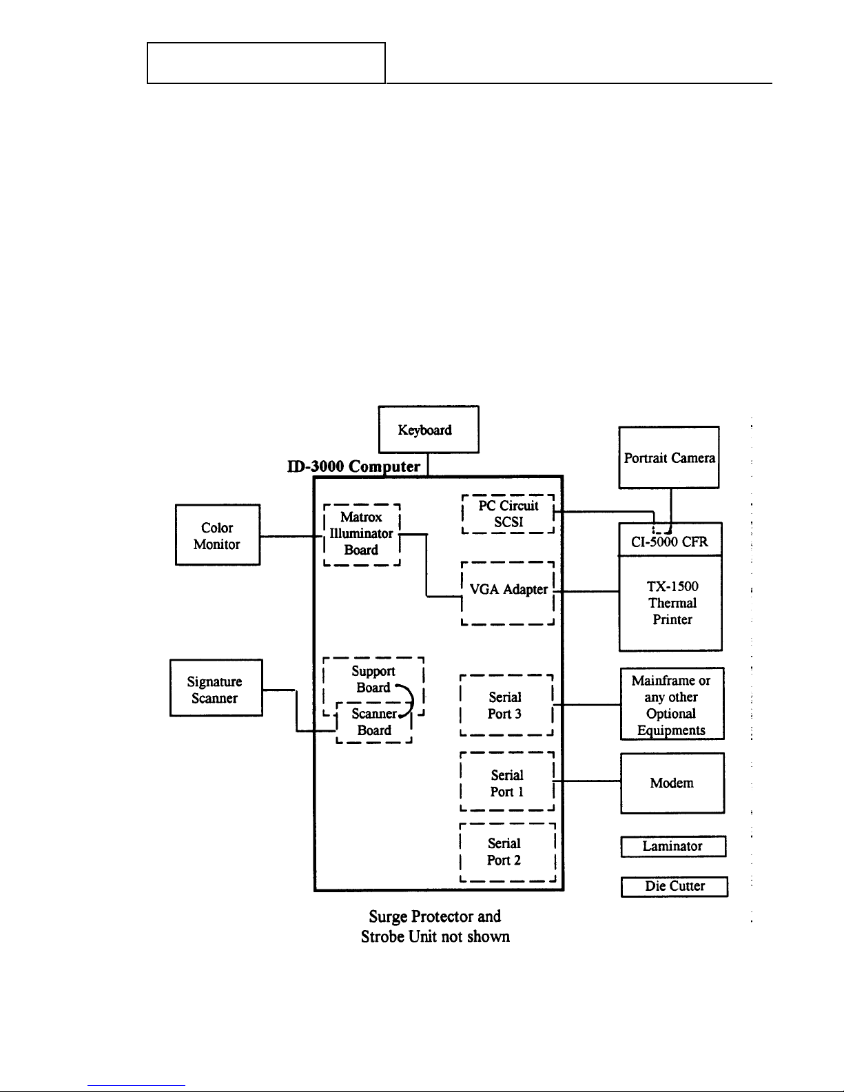
Figure 1-2 shows the system hardware in block diagram form, and Table 1-1 explains the
component functions.
Figure 1-2 ID-3000 System hardware
1-5

Polaroid ID3000 Service Manual Description
Table 1-1 ID-3000 System hardware component functions
Workstation Controls input & output units, stores portraits, data, signatures, and card
Computer formats; captures, manipulates and combines portraits, signatures & data
with card format, for printing by the color film recorder (CI5000) or
thermal printer TX1500. Can be configured to exchange data with a
mainframe host.
Keyboard Enters text data; communicates with computer.
13" Color Displays menus, prompts, messages & applicant data. Also displays the
Monitor applicant's portrait (as captured by the portrait camera or as stored in
the system), and any other identification images captured or stored by
the system.
Color Converts the applicant image into a video signal for use in creating the ID
Camera Portrait card and for electronic storage. Includes an electronic flash unit for
Camera consistently color- balanced high-quality portraits.
Signature Scans the applicant’s signature from the signature card for storage, monitor
Scanner display and printing on ID card.
Color Film Exposes portrait, signature, data and format elements (company name,
Recorder logo, etc.) on Polaroid instant film, in vertical or horizontal format.
(CI5000) and Contains power supply and connections for monitor, portrait camera and
Camera back electronic flash. Camera Back attached to CI5000 holds film pack in
(ID3000 position, and initiates development when film is pulled through rollers.
System only) Permits one or two cards per film sheet.
Color Prints full-color ID card image (including portrait and other images), ready
Thermal for die cutting and laminating. Printer contains a power supply and
Printer connections for the display, portrait camera and electronic flash.
TX1500
(ID3000 T
Systems only)
Die Cutter Die cuts developed ID cards from sheet of Polaroid instant film. One card/
film sheet and two cards/film sheet models available.
Laminator Heat-seals die-cut ID card in a tough, tamper-resistant, long-life plastic
enclosure.
Surge Protects System from AC power line surges.
Protector
1-6
Polaroid ID3000 Service Manual Description
ID-3000 System Functions
Simple operation is provided by monitor display of menu choices and prompts, to which the
operator responds by typing appropriate answers with the keyboard. Automated diagnostics
help speed identification and correction of operator errors or system malfunctions.
After log-in by typing a username and password and selecting Issue or Verify Badges from the
Main Menu, the system asks the operator to set the film counter by entering the film tab
number.
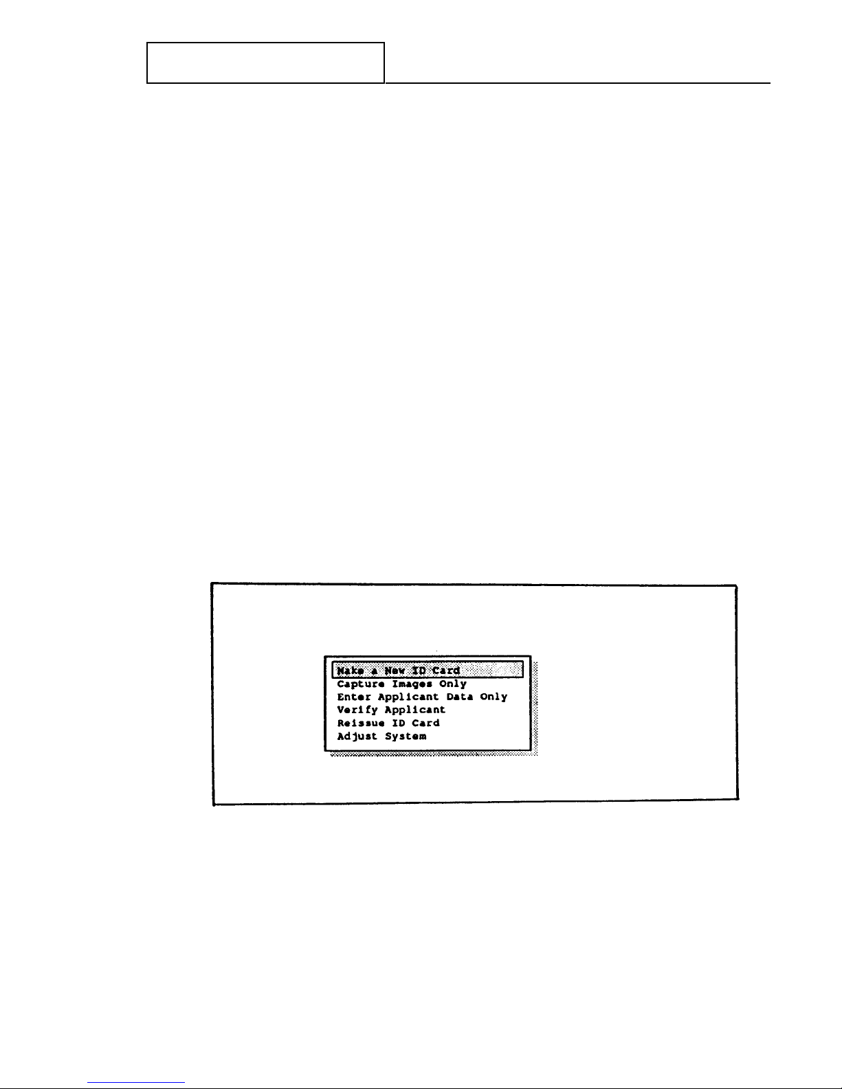
When these two operations have been done correctly, the system then displays the Operator’s
Menu (Figure 1-3). The six choices offered by this menu are explained below. Menu and
screen selections are easily made by either highlighting the choice or typing the first letter of
the choice; help screens for most menus and screens further simplify and speed system use.
(See the ID-3000 System Operator’s Guide for detailed explanations of all operating steps.)
Make a New ID
Guides the operator in issuing an ID card to an applicant who has not had a card made with
this system, or updating an applicant’s portrait, signature and data before issuing a replacement card. Steps involve capturing and storing the new portrait, signature and applicant data,
and producing an ID card. Film develops in 90 seconds (or thermal image is printed), and is
then die cut and laminated. Applicant’s portrait, signature and text data previously stored
remain in the system or host disk.
Figure 1-3 Operator’s Menu
1-7

Polaroid ID3000 Service Manual Description
Capture Portrait and Signature
Permits capturing and storing the applicant’s portrait and signature so that an ID card can be
made at a later time.
Enter Applicant Data Only
Used for entering or updating applicant data only, without capturing a portrait or signature.
Verify Applicant
Permits recalling previously stored applicant data, portrait and signature for review.
Reissue ID Card
Permits reissuing an ID card using a portrait and signature previously stored, or, with Capture Portrait and Signature menu option, to issue a new ID card using previously stored
portrait, signature and data.
Adjust System
Allows changing the ID card tint; lightening or darkening the card or the portrait; changing
the film processing time. Adjust the Signature Scanner and Color Portrait Scanner when
available.
1-8
Polaroid ID3000 Service Manual Description
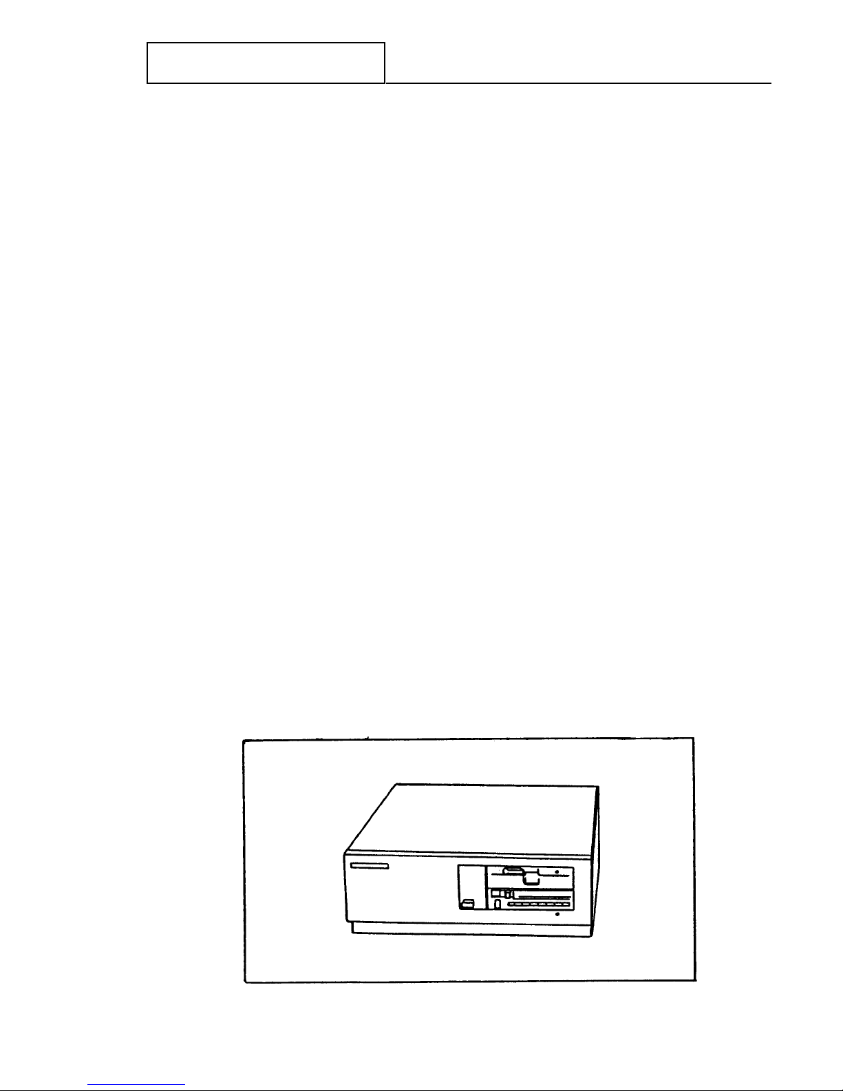
ID-3000 Workstation Computer
The System computer (Figure 1-4) controls the operation of all other ID-3000 System input
and output hardware, and with the keyboard and monitor, provides the means for communication between the system and the operator.
The computer in the ID-3000 workstation is a Hewlett-Packard Vectra Model QS/20 386*,
using the 32-bit Intel 80386 microprocessor. Principal features include:
8mb Simm RAM (on HP CPU Board)
1.2mb 5.25" floppy disk drive
SCSI hard disk drive and controller (48mb, 85mb, 120mb, 180mb, 240mb, 340mb or
760mb)
SCSI tape backup (150/250mb or 525mb)
Super VGA Adapter Card
Matrox Illuminator Board
Support Board
Data compression board (DSP)
Network interface - in systems configured for mainframe networks (optional)
Two serial ports and one parallel port are standard; four serial ports and one parallel
port are optional
*NOTE: Model currently supplied. The computer and other system hardware is
subject to change at any time.
Figure 1-4 ID-3000 HP Vectra QS/20 Workstation Computer
1-9
Polaroid ID3000 Service Manual Description
Board Descriptions
Polaroid DSP Board — in conjunction with software algorithms, compresses images from
300 kbytes to and average of 8 kbytes.
AST I/O Board — provides two serial ports and one parallel port.
Matrox Illuminator Board — digitizes analog signal from the portrait video camera; sends
digital signal to the Color Film Recorder (CI5000) in ID-3000F System, or Thermal Printer in
the ID- 3000T System.
Super VGA Adapter Card — transfers data from the CPU to the color monitor.
SCSI and Floppy Controller Board — interface between the CPU and system drives and
components.
HP CPU Board — computer’s central processing unit. Interprets and executes instructions
by performing arithmetic operations, controlling instruction processing, and providing timing
signals and other housekeeping operations.
Polaroid Support Board — controls strobe firing, auto lens, and signature scanner (when
used).
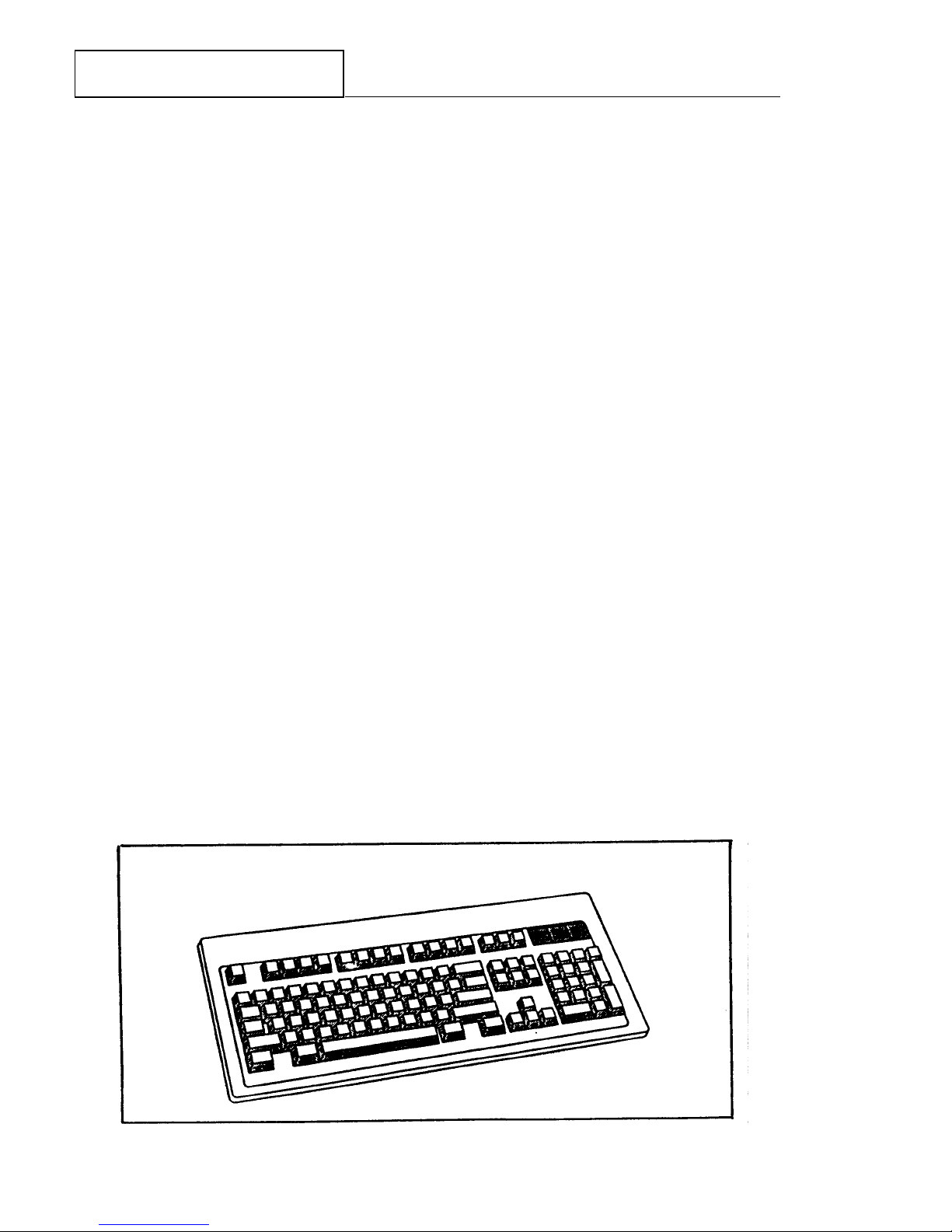
Computer Keyboard
The HP Vectra Enhanced Keyboard, for controlling the system through the computer and
inputting applicant data, has 101 keys arranged as shown in Figure 1-5. Keyboards are
supplied with the ID-3000 System for either U.S., French, German, Spanish, Japanese, U.K./
English, Italian or French Canadian languages, depending on the customer’s choice. (See the
HP Vectra QS Operator’s Manual, pages 10-9 to 10-14 for illustrations of these keyboards.)
. Figure 1-5 HP Vectra Enhanced Keyboard
1-10
Polaroid ID3000 Service Manual Description
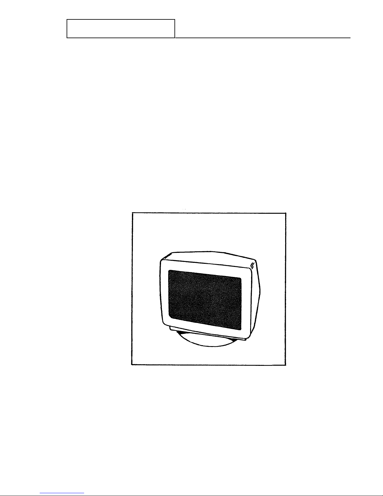
13" Color Monitor
The HP D1182 Video Graphics Color Display is a high-resolution color CRT display unit with
maximum screen resolution of 640 x 480. It offers minimum screen distortion and a 0.28mm
dot pitch, analog video input able to display an infinite number of colors, and anti- glare silica
screen coating. Power, brightness and contrast controls are located on the front panel.
Figure 1-6 13" Color Monitor
1-11

Polaroid ID3000 Service Manual Description
Color Portrait Camera
The ID-3000 System camera (Figure 1-7), which captures the live portrait of the applicant, is
a JVC TK-87OU color video camera equipped with either a 16mm (standard) or 25mm
(optional) auto-iris lens.
The Camera has a solid-state CCD image pickup element capable of producing excellent print
quality free of latent images and distortion. Horizontal resolution is 330 TV lines. RGB
primary color filter system yields excellent color reproduction. Operating voltage is 12 VDC.
Figure 1-7 Color portrait video camera and strobe unit
Portrait Lighting
Lighting for the applicant’s face image is provided by a Vivitar Model 283 Strobe unit
mounted in a shoe on the top of the Camera and Strobe Bracket Assembly (Figure 1-7).
Strobe light output is triggered by the Support Board in the computer. Strobe operating
power is supplied by the power supply in the CI-5000 Assembly or TX-1500 Assembly.
1-12
Polaroid ID3000 Service Manual Description
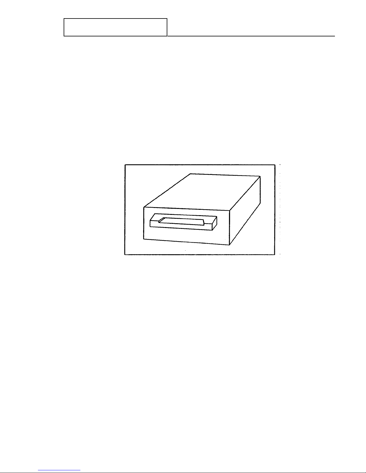
Signature Scanner
The optional Signature Scanner captures the applicant’s signature from a specially-designed
signature card.
The ID-3000 system prints the signature on the identification card for added security.
The ID-3000 system also stores the signature electronically for card reissue or verification.
.
.
.
Figure 1-8 Signature Scanner
1-13
Polaroid ID3000 Service Manual Description
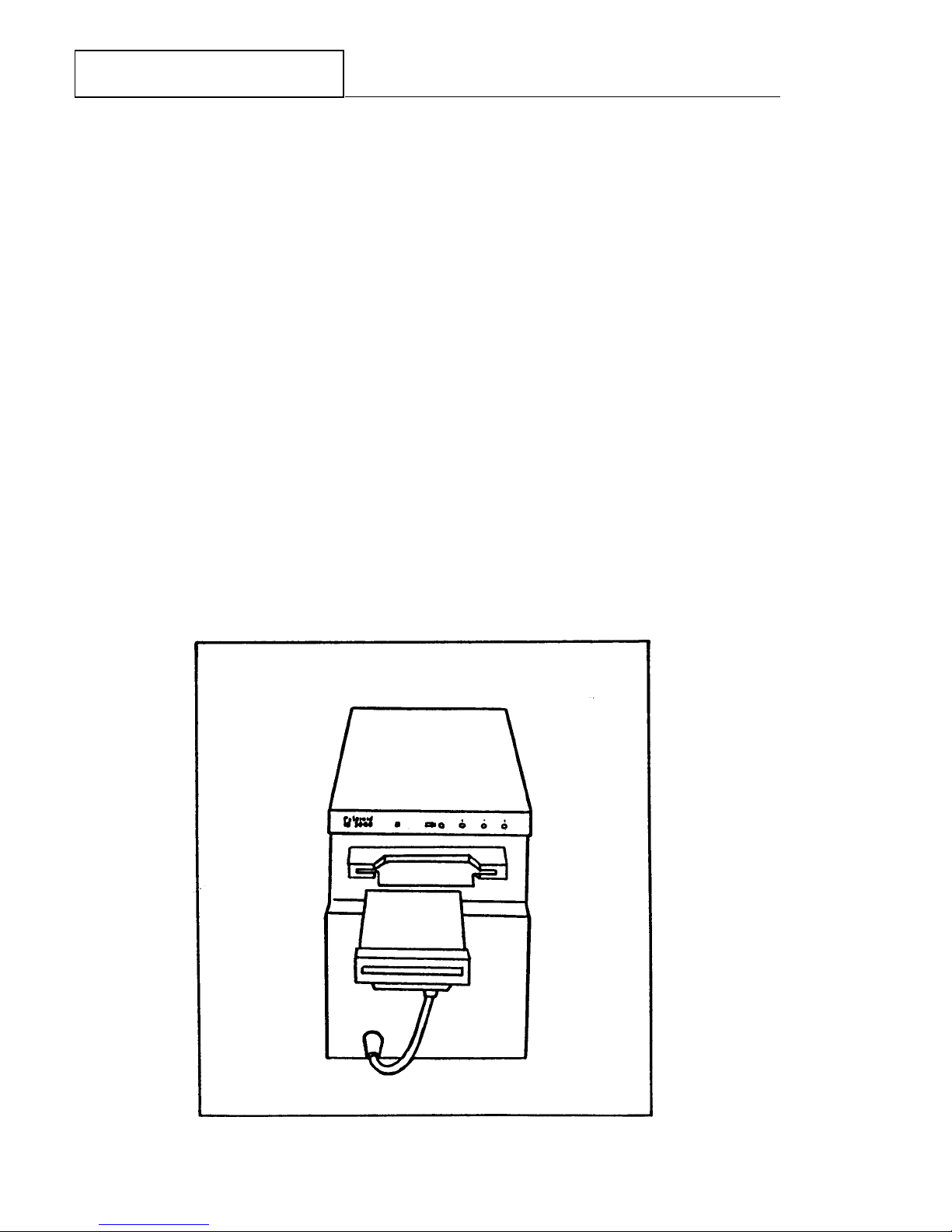
Color Film Recorder (CFR) and Camera Back
The Polaroid CI-5000 CFR (Figure 1-9) prints full-color ID card images on Polaroid instant
film, from digital signals from the Matrox Illuminator Board in the System computer. (An ID3000 System equipped with a CI-5000 Color Film Recorder is designated as an ID-3000F
System.)
Images contain the portrait, signature, text and other distinctive format elements, and are
ready for die-cutting and laminating 90 seconds after the start of the exposure cycle.
A single camera back on the CI-5000 can produce either one or two ID cards per sheet of
film. When two cards per film sheet are to be made, the CI-5000 electronically stores the first
card image in memory until the second card image has been recorded. Both images are then
printed on the film sheet when the EXPOSE command is used. (To print a card after only one
image has been exposed, the FORCE command is used; see Section 2, “Making an identification card”, step 15.)
A front-panel LED flashes during the exposure process, when EXPOSE is selected after the
second exposure has been made in a 2-up system (or FORCE is selected after one exposure).
When exposure is completed, the front-panel “Pull Film” LED flashes and an audible beep
sounds, signaling the operator to pull the white tab and then the yellow tab of the exposed
frame from the camera back. When the 90-second film development time has elapsed, another
LED lights to inform the operator to peel the film negative from the print.
Figure 1-9 Color Film Recorder Assembly used in ID-3000F System
1-14
Polaroid ID3000 Service Manual Description
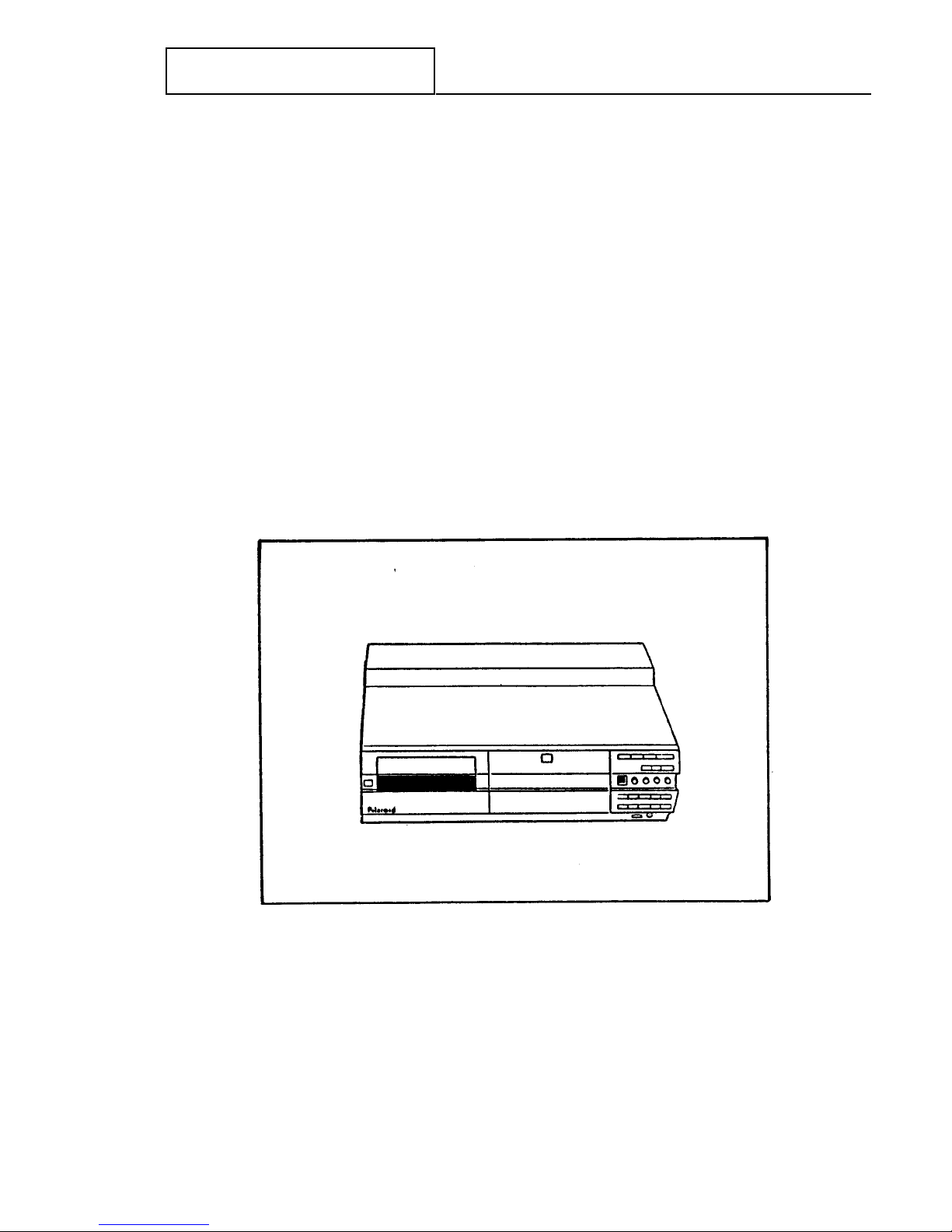
Thermal Color Printer
The Polaroid TX-1500 Color Thermal Printer (Figure 1-10) is a customer-selected output
alternative to the CI-5000 CFR described earlier. An ID-3000 System equipped with a TX1500 Printer is designated as an ID-3000T System.
The TX-1500 produces either one or two full-color ID card images on a single 4 x 5" (100 x
128mm) sheet. Print time is about 110 seconds after the frame button has been pressed. The
printing system is a dye diffusion thermal transfer process, which uses a three-color ink cartridge and paper supplied as a set.
Picture quality is characterized by 2.1 million available colors, 128 gray levels and 464 x 616
dots. On screen controls include color, tint, contrast and brightness.
.
Figure 1-10 TX-1500 Color Thermal Printer used in ID-3000T System
1-15
Polaroid ID3000 Service Manual Description
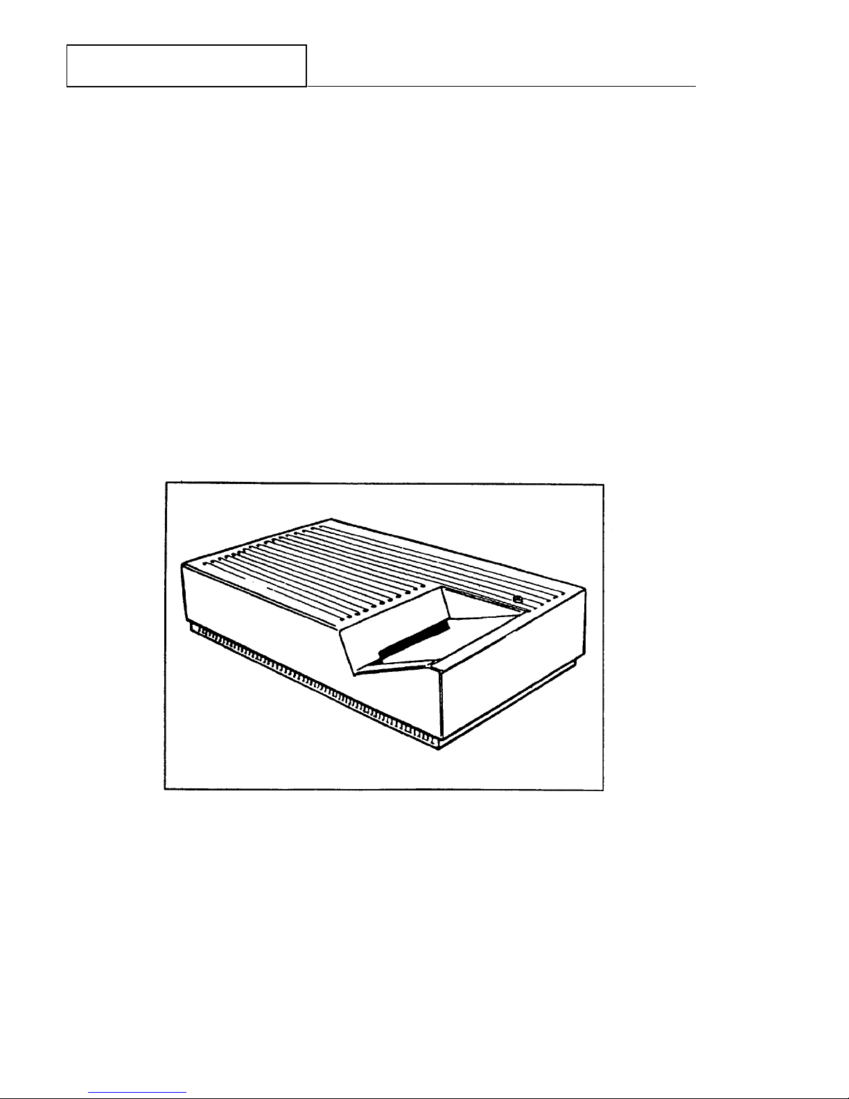
Digital Color Scanner (optional)
The Digital Color Scanner is a high-speed computer peripheral which captures and digitizes
images from color and black & white photographs or other reflective graphics. It accepts
documents up to 4.12 by 8.50 inches. Maximum scanning area is 4 by 6 inches.
The scanner uses state-of-the-art charge coupled (CCD) technology and scans at very high
speeds.
Figure 1-11 Digital Color Scanner
1-16
Polaroid ID3000 Service Manual Description
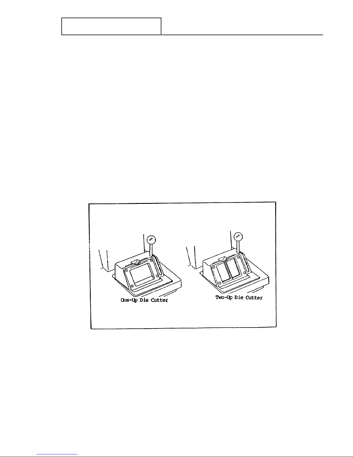
Die Cutter
Die Cutters for the ID-3000 System smoothly and accurately cut the ID card(s) to proper size,
from the Polaroid photographic or thermal print. They operate manually when the handle is
pulled forward.
Two versions are available:
1-Up CR-80 (2-1/8" x 3-3/8" ID cards)
2-Up std. for CR-60 (1-3/4" x 2-1/4" ID cards)
1-Up or 2-Up CR-79 (1-7/8" x 3-1/8" ID cards)
Laminator
The Laminator (Figure 1-13) for ID-3000 Systems heat-seals the die- cut ID card into a
protective, durable plastic pouch.
Features of this self-contained, electrically-operator Laminator include automatic roller start
when an optical switch senses a card has been inserted into the Laminator, and automatic AC
Figure 1-12 ID-3000 System Die Cutters
1-17
Polaroid ID3000 Service Manual Description
voltage level switch for compatibility with line voltages world-wide.
One Laminator model is for use with photographic prints produced by the CI-5000 CFR,
another Laminator model is for use with prints produced by the Color Thermal Printer
TX1500. (Units are not interchangeable in application.)
Figure 1-13 ID-3000 System ID card Laminators
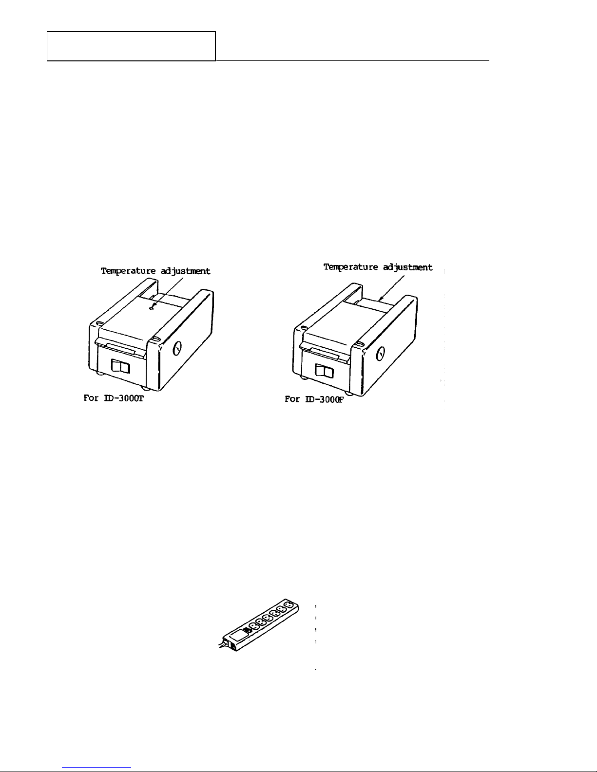
Surge Protector/Power Strip
The six-receptacle power outlet strip shown in Figure 1-14 includes a filter/surge protector
circuit to protect ID-3000 System components against AC line surges and spikes. An illuminated rocker switch allows turning AC power on or off to all units plugged into the strip.
Figure 1-14 Surge Protector/AC Power Outlet Strip
1-18

Polaroid ID3000 Service Manual System Installation
SECTION 2 - SYSTEM INSTALLATION
Contents
Page
Software, Tools & Equipment required 2-3
Major Installation Steps 2-3
Powering Up the System 2-12
Loading Paper and Ink 2-13
Care & Handling of Paper, Ink and Prints 2-14
Functional Check of the System 2-16
Setting Film Counter 2-17
Making an Identification Card 2-18
Storing a Portrait and Signature 2-25
Entering Applicant Data Only 2-27
Verifying Applicant Data 2-29
Reissuing an Identification Card 2-30
Adjusting the Card for the ID3000 Film System 2-34
Adjusting the Color Card for the ID3000 Thermal System 2-39
Adjusting the Color Portrait Camera 2-44
Adjusting the Signature Scanner 2-48
Portrait Scanner Adjustment 2-51
Calibrating the Scanner 2-51
Adjusting the Portrait Capture Area 2-52
Restoring the Factory-Set Capture Area 2-55
Changing the Film Type Setting 2-57
Exiting from the System 2-59
Checking Laminator Temperature 2-60
2-1

Polaroid ID3000 Service Manual System Installation
This page intentionally blank.
2-2

Polaroid ID3000 Service Manual System Installation
SECTION 2 — ID-3000 SYSTEM INSTALLATION
Software, Tools and Equipment
The following equipment and materials are needed for ID-3000 System installation:
Multimeter Calibration and Diagnostic Diskettes
Field Service Toolkit (may be included within the ID3000
(see Section 4) Tools Diskette)
Installation Toolkit Color Calibration Card #1B2195A
ID-3000 Installation and Grounding strap
Service Manual
Major Installation Steps
Installation consists of the following procedures performed in sequence:
1. Laying out the installation site
2. Unpacking and assembling the system
3. Checking computer internal connections
4. Installing cables
5. Powering up the system, log-in and main menu display
6. Functionally checking system performance:
Setting film counter
Making an identification card
Storing a portrait and signature
Entering applicant data only
Verifying applicant data
Reissuing an identification card
Adjusting the system
Exiting from the system
7. Checking Laminator Temperature
2-3
Polaroid ID3000 Service Manual System Installation
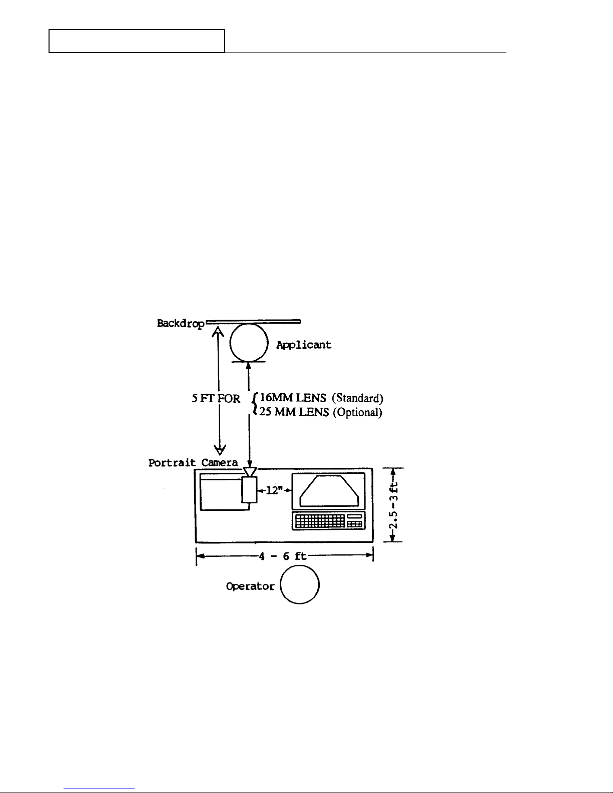
Laying out the installation site
Sufficient space must be available to allow the layout shown in Figure 2-1. (The installation technician should call ahead to verify space availability before proceeding to the site.) Particularly important is the camera-to-subject distance.
NOTE: For ID-3000F System, place CI-5000 Color Film Recorder Assembly at least 12" away
from VGA Monitor to prevent electrical interference.
Figure 2-1 Typical ID-3000 layout
2-4
Polaroid ID3000 Service Manual System Installation
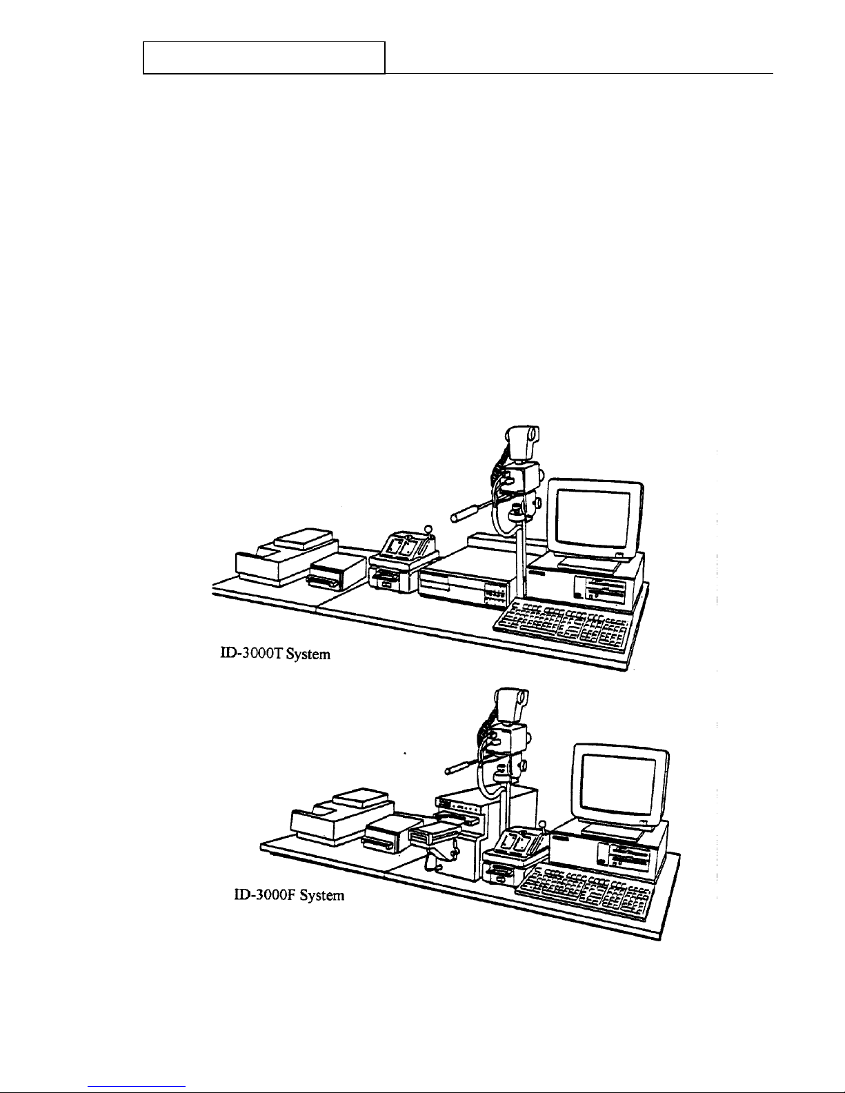
Unpacking and assembling the system
1. Carefully unpack all system components (computer, keyboard, monitor and swivel base,
portrait camera, strobe, thermal printer & power supply assembly (3000T system) or color
film recorder & power supply assembly (3000F system), signature scanner (optional), color
scanner (optional), power outlet strip, die cutter and laminator), and place them as shown in
Figure 2-2 or some comparable arrangement.
NOTE: Figure 2-2 shows an optimal ID-3000 system arrangement.
Yours may be different.
NOTE: Computer may be placed on its side, if space is limited.
I
Figure 2-2 Optimal ID-3000 system setup
2-5
Polaroid ID3000 Service Manual System Installation
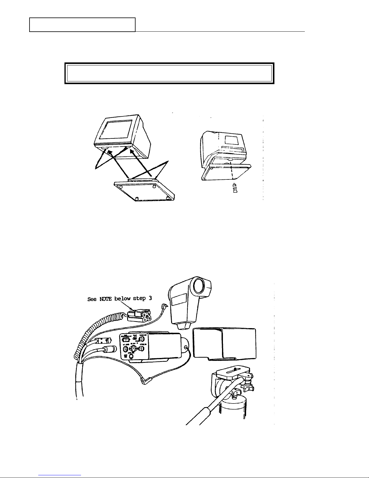
2. Mount the monitor on the swivel base (see Figure 2-3): invert the monitor, engage front
edge of base under tabs on monitor, snap pin into hole at back of base.
Note: The latest monitor does not require mounting to the swivel base.
Figure 2-3 Mounting Color Monitor on Swivel Base
Figure 2-4 Mounting Camera, Strobe and Bracket Assembly
2-6

Polaroid ID3000 Service Manual System Installation
3. Assemble the color portrait camera and strobe as follows (see Figure 2-4): slip camera/
strobe bracket over camera; attach bracket to microfluid tripod head by tightening tripod
screw; attach strobe to shoe on top of bracket; connect the five cables in the cable
assembly to the appropriate connectors on lens barrel, strobe and back of camera. Hold
the camera pole close to the output unit (film recorder or thermal) and insert the two thumb
screws and hand-tighten them.
NOTE: Before inserting the power supply plug into the strobe, be sure the plug locking tab
is fully retracted (turn the thumbwheel in the plug to the left as far as it will go).
Then open the strobe battery compartment and insert the power plug. Press down on
the plug and rotate the thumbwheel in the plug to the right as far as it will go, to
engage the plug locking tab with the plug socket.
4. For ID-3000F System, attach the Camera Back to the front of the Color Film Recorder &
Power Supply Assembly, as shown in Figure 2-5. Finger-tighten the two thumbscrews.
5. Place the Die Cutter on top of the Laminator and plug the power cord from the Laminator
into the Power Strip.
Figure 2-5 Attaching the Camera Back to the Film Recorder
2-7
Polaroid ID3000 Service Manual System Installation
Checking computer internal connections
Computer circuit boards and cables can loosen during shipping and cause malfunctions. Check them
as follows before proceeding further with installation:
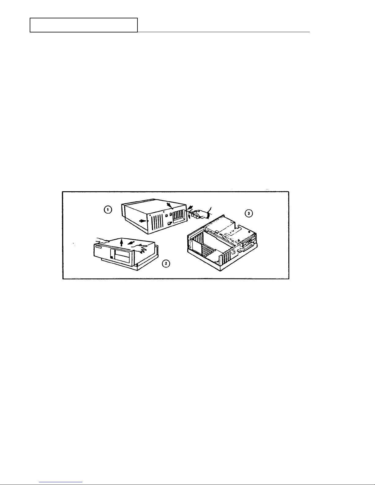
1. Remove the computer cover (Figure 2-6).
2. Visually inspect all computer components to assure they are fully seated in their slots,
sockets and board guides, and that all cable connections are secure, especially the alpha
cable that connects between the matrox board and the VGA board.
3. Inspect the battery wire and its connection to the board, and tighten if necessary.
4. Replace the computer cover.
.
Figure 2-6 Removing the Computer Cover
2-8
 Loading...