

Page 1

32” LCD Television with NTSC/ATSC Tuner
20060215
FLM-3232
Page 2

FCC
Federal Communications
Commission Statement
This equipment has been tested and found to comply with the limits of a class B digital device,
pursuant to Part 15 of the FCC Rules. These limits are designed to provide reasonable protection
against harmful interference in a residential installation. This equipment generates, uses and can
radiate radio frequency energy and, if not installed and used in accordance with the instructions, may
cause harmful interference to radio communications. However, there is no guarantee that
interference will not occur in a particular installation. If this equipment does cause harmful
interference to radio or television reception, which can be determined by turning the equipment off
and on, the user is encouraged to try to correct the interference by one or more of the following
measures:
1. Reorient/Relocate the receiving antenna.
2. Increase the separation between the equipment and receiver.
3. Connect the equipment into an outlet on a circuit which is different from what the receiver is
connected to.
4. Consult the dealer or an experienced radio/TV technician for help.
Changes or modifications not expressly approved by the manufacturer
responsible for compliance could void the user authority to operate the
equipment.
ENGLISHENGLISH
1
Page 3

Warnings and Precautions
Warnings and Precautions
To prevent any injuries, the following safety precautions should be observed in the installation, use,
servicing and maintenance of this equipment.
Before operating this equipment, please read this manual completely, and keep it nearby for future
reference.
This symbol is intended to alert the user to avoid the risk of electric shock.
WARNING
CAUTION
This equipment must not be disassembled by anyone except qualied service personnel.
This symbol is intended to alert the user to the presence of important operating and
maintenance instructions in the literature accompanying the appliance.
To reduce the risk of re or electric shock, do not expose this equipment to rain or moisture.
▪ TO REDUCE THE RISK OF ELECTRIC SHOCK,
▪ DO NOT REMOVE COVER (OR BACK).
▪ NO USER-SERVICEABLE PARTS INSIDE.
▪ REFER SERVICING TO QUALIFIED SERVICE PERSONNEL.
Use of controls, adjustments or performance of procedures other than those specied herein
may result in hazardous radiation exposure.
Important Safety Instructions
This symbol indicates caution points.
This symbol indicates actions that should not be done.
This symbol indicates actions that must be performed.
▪ Do not place the equipment on any uneven or unstable carts, stands, tables, shelves etc.
The equipment may fall, causing serious injury to children or adults and serious damage
to the equipment itself.
▪ Use only a cart or stand recommended by the manufacturer. This equipment and
recommended cart or stand should be handled with care. Quick stops, excessive force,
and uneven surfaces may cause the equipment and cart/stand to overturn.
▪ Do not disable the 3-wire grounding type plug. The grounding pin on the 3-prong plug is
an important feature. Removing the grounding pin will increase the risk of damaging the
equipment.
▪ If you can not t the plug into the electrical outlet, contact an electrician to install a
grounding outlet.
▪ Always operate this equipment from the type of power source indicated on the rear of the
serial/model plate.
2
Page 4

Warnings and Precautions
▪ Never overload wall outlets and extensions.
▪ Use and handle the power cord with care. Do not place any heavy objects on the AC
power cord.
▪ Do not pull the AC power cord. Do not handle the AC power cord with a wet hand.
▪ Do not touch the power cord and antenna cable during lightning.
▪ Remove the plug from the wall outlet, if the equipment will not be used for a long period
of time.
▪ Do not place, use or handle this equipment near water.
▪ Never expose the equipment to liquid, rain, or moisture.
Seek for service if any of the above is spilled into the equipment.
▪ Do not expose the equipment to extreme temperature or to direct sunlight, as the
equipment may heat up and suffer damage.
▪ Do not install the equipment near any heat sources such as radiators, heat registers,
stoves, or any other apparatus that might produce heat.
▪ Do not attempt to service the equipment yourself.
▪ Opening and removing the covers may expose you to dangerous voltage or other
hazards and may void your warranty. Refer service to qualied personnel.
▪ Do not place or drop any other objects on top.
▪ Do not insert anything into the ventilation holes of your equipment.
Inserting any metal or ammable objects may result to re or electric shock.
ENGLISHENGLISH
▪ Do not place the equipment on uneven or unstable carts, stands, tables, shelves etc. The
equipment may fall, causing serious injury to children or adults and serious damage to
the equipment itself.
Always place the equipment on the oor or on a surface that is sturdy, level, stable and
strong enough to support the weight of the equipment.
▪ Do not block any ventilating openings. Leave an open space around the equipment.
Never place the equipment :
on a bed, sofa, rug, or any other similar surfaces; too close to drapes/curtains/walls, in a
bookcase, built-in cabinet, or any other similar places that may cause poor ventilation.
▪ Always remove the power cord from the outlet before cleaning the equipment.
▪ Never use liquid or aerosol cleaners on the equipment.
Clean only with a soft dry cloth.
3
Page 5

Warnings and Precautions
Outdoor Antenna Safety Instructions
If an outdoor antenna is connected, follow the precautions below:
▪ An outdoor antenna should not be located in any area where it could come in contact with
overhead power lines, or any other electric light or power circuits.
▪ When installing an outdoor antenna system, extreme caution should be taken to prevent
contact with power lines. Direct contact with power lines may be fatal and should be avoided
at all costs.
Section 810 of National Electrical Code (NEC) provides information with respect to proper grounding of the
mast and supporting structure, grounding of the lead-in wire to an antenna discharge unit, size of grounding
conductors, location of antenna discharge unit, connection to grounding electrodes, and requirements for
the grounding electrode.
Antenna lead-in wire
Ground clamps
Electric service
equipment
Ground clamps
Power service grounding
(NEC Art250 part H)
NEC : National Electrical code
EXAMPLE OF OUTDOOR ANTENNA GROUNDING
4
Antenna discharge unit
(NEC section 810-20)
Grounding conductors
(NEC section 810-20)
Page 6

TABLE OF CONTENTS
Federal Communications Commission Statement .......................... 1
Warnings and Precautions
Important Safety Instructions ....................................................................................... 2
Antenna Safety Instructions ......................................................................................... 4
Chapter 1 Introducing the LCD TV
Key Features ............................................................................................................... 6
Package Contents ....................................................................................................... 7
Setting Up Your LCD TV .............................................................................................. 8
Your LCD TV .............................................................................................................. 10
Your Remote Control ................................................................................................. 12
Chapter 2 Installing the LCD TV
Connecting a TV Cable or an Antenna ...................................................................... 14
Connecting a VCR ..................................................................................................... 18
Connecting a Video Camera or Play Station ............................................................. 19
Connecting a DVD Player .......................................................................................... 20
Connecting a Digital TV Cable Box or Digital Satellite Receiver ............................... 22
Connecting an AV Equipment with HDMI Connector ................................................. 23
Connecting an AV Equipment with DVI Connector .................................................... 24
Connecting a PC........................................................................................................ 25
Connecting an Audio Receiver or a Dolby Digital 5.1 Sound System........................ 26
ENGLISHENGLISH
Chapter 3 USING THE FEATURES
Using Picture-In-Picture ...................................................................................27
Wide Screen Viewing ......................................................................................29
Operating the Menu ........................................................................................30
Setting up the HDTV Function ..........................................................................32
Customizing the VIDEO Settings ......................................................................35
Customizing the AUDIO Settings ......................................................................36
Customizing the SETUP Settings......................................................................37
Using the V-CHIP Settings ............................................................................... 39
Using the Parental Settings .............................................................................. 41
Customizing the TV Settings ............................................................................42
Specications......................................................................................................... 43
Chapter 4 Programming your Remote Control
Introduction................................................................................................................ A
Programming a Device ............................................................................................. A
Troubleshooting ......................................................................................................... B
Manufacturer’s Codes ............................................................................................... C
5
Page 7

Chapter 1 Introducing the LCD TV
Chapter 1
Introducing the LCD TV
Key Features
Various Audio/Video terminals for external equipment connection
▪ 2 set of composite A/V input terminals
▪ 1 set of S-VIDEO terminals
▪ 2 set of component Video input terminals
▪ 1 VGA/ Audio input terminal
▪ 1 HDMI/Auido input terminal
▪ 1 sets of Audio(L/R) output terminals
▪ 2 SPDIF output terminal (Optical x 1 /Coaxial x 1)
▪ 1 Headphone terminal
The built-in TV tuner to receive HD ATSC
▪ This function allows the reception of HD broadcasting without the addition of a set top
box.
High Definition Multimedia Interface (HDMI)
▪ High Denition Multimedia Interface (HDMI) is a small, user-friendly interconnect that
can carry up to 5 Gbps of combined video and audio in a single cable. This system
eliminates the cost, complexity and confusion of multiple cables used to connect
current A/V systems.
HDTV Component Video Inputs
▪ Offers the best video quality for DVD(480p) and digital set-top-box (HD1080i, 720p)
connections.
3D Digital Noise Reduction
▪ This function can digitally reduce image noise to provide better picture quality.
Film-Mode Detection (3:2 Reverse Pull Down)
▪ This function can automatically detect content derived from lm and adjust the
interlacer’s frame matching to provide a more natural-looking, clearer image of the
moving picture.
PIP Function
▪ Provides viewing of two programs simultaneously, in either picture-in-picture mode or
picture-on-picture (side by side) mode.
6
Page 8

Package Contents
AA Batteries x 2
User’s Manual
Component Cable
Quick Start Guide
Chapter 1 Introducing the LCD TV
Make sure all of the following contents are included.
LCD TV
Power Cord
VIDEO Cable Remote Control/
AUDIO Cable Warranty Card
ENGLISH
Bottom Stand /
Screw Driver and 6 Screws
These items are all you need to set up and operate the LCD TV in its basic conguration.
Make sure all of the above contents are included in the package. If you are missing
any items, please contact the Polaroid customer service department.
7
Page 9

Chapter 1 Introducing the LCD TV
Stand
Shipping Box
Packaging Material
Table
Unit
Table
Packaging
Material
Stand
Screws (6)
Stand
Unit
Table
Packaging
Material
Setting Up Your LCD TV
Attach the Stand
If you prefer to mount your new Polaroid TV on a wall instead of attaching it to the stand, please reference
the instructions included in the wall mounting kit (not included).
IMPORTANT: Attach the Stand to the TV with the bottom foam packaging material still attached.
Read all instructions before continuing with the stand installation.
a) Lift foam packaging material from the top of the TV out of the box.
b) Lift TV out of box, with the bottom foam packaging material still attached, and place onto a stable surface.
c) Remove the protective bag from the LCD unit, but DO NOT remove the bottom foam packaging material.
d) Locate the place on the back of the TV to attach the stand. Secure the stand to the LCD with all six screws.
8
Page 10

Chapter 1 Introducing the LCD TV
Use a supplied antenna cable to connect the VHF/UHF signal to the LCD TV’s ANT. terminal
(refer to page17).
Connect the AC power cord at the back of the TV and connect the power cord to wall outlet.
Insert the 2 batteries supplied in remote control.
Step1 Slide the back cover up to open the
battery compartment of the remote
control.
Step2 Insert two AA size batteries.
Make sure to match the (+) and
( - ) ends of the batteries with
the (+) and ( - ) ends indicated
in the battery compartment.
Slide the cover back into place.
ENGLISH
Do not use caustic cleaners (porcelain, stainless steel, toilet, or oven cleaner
etc.) on the remote, as it may suffer damage.
Connect other an external A/V device (refer to page14-26).
9
Page 11

L
R
VIDEO1 IN
VIDEO
AUDIO
Chapter 1 Introducing the LCD TV
Your LCD TV
Front/Right Side View and Controls
LED
The LED light indicates when the LCD TV is
activated.
IR
Infrared
Receiver
VOLUME▲▼
Adjusts the volume up and down.
Selects the main-menu item and change
values for items when in the OSD mode.
CHANNEL▲▼
Scans up and down through channels.
Selects sub-menu item when in the OSD
mode.
MENU
Press once to display the OSD (on screen
display), press again to turn the OSD off.
INPUT
Chooses from different input signal sources.
Turns the LCD TV on and into standby mode.
10
VIDEO1 IN
Connects to the composite
Video and Audio output jacks
on external video equipment.
EARPHONE
Connects to the external
headhone for private
listening.
Page 12

HDMI IN
AUDIO
L R
L R L R
L R
L
R
L R
L R
AUDIO
VGA IN
VIDEO2 IN
VIDEO AUDIO
S-VIDEO IN
S-VIDEO AUDIO
YPbPr1 IN
AUDIO OUT
STEREO
DIGITAL
OPTICAL
COAXIAL
TV
CABLE
HDTV
AIR
VHF/UHF IN
Y Pb Pr AUDIO
YPbPr2 IN
Y Pb Pr AUDIO
Rear View and Jacks
VIDEO2 IN
Connects to the composite VIDEO and AUDIO(L/R) output jacks on external video equipment.
Chapter 1 Introducing the LCD TV
HDMI IN
Connects the all digital AV equipment with HDMI connector.HDMI supports enhanced,
high-denition video and two-channel digital audio. The AUDIO(L/R) of HDMI IN is for
DVI connection.
S-VIDEO IN
Connects to the S-VIDEO and AUDIO(L/R) output jacks on external
video equipment.
VGA IN
Connects the PC, or other AV equipment with VGA and
AUDIO(L/R) output jacks.
ENGLISH
YPbPr1 IN/YPbPr2 IN
Connects to the DVD player, Digital Set-Top-Box, or other AV
equipment with component(YPbPr) video and audio output jacks.
AUDIO OUT-STEREO
Connects to the AUDIO(L/R) input jacks on AV equipment.
AUDIO OUT-DIGITAL-OPTICAL/COAXIAL
Connects to the OPTICAL AUDIO jack on the digital/standard 5.1
audio system.
VHF/UHF IN-TV-CABLE
Connects RF input from VHF/UHF antenna or cable.
VHF/UHF IN-HDTV-AIR
Connects RF input from VHF/UHF antenna or cable
to receive high/standard denition television.
AC IN
Connects to the AC power cord.
11
Page 13

Chapter 1 Introducing the LCD TV
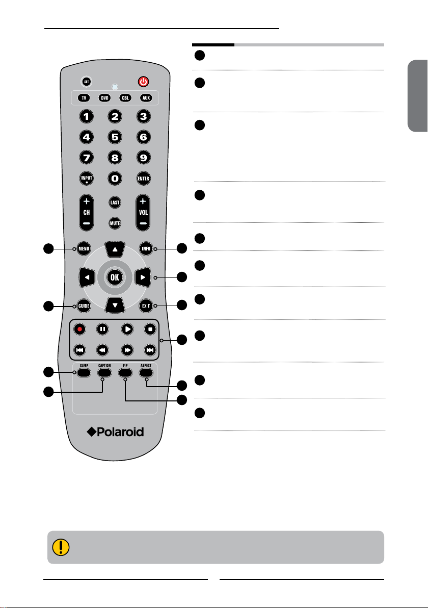
Your Remote Control
This package includes a Polaroid remote that enables control of up to four devices.
To select a device, simply select one of the following device mode controls: TV, CBL/SAT, DVD/VCR,
or AUDIO.
Turns the LCD TV on and off.
1
2
3
5
1
4
SET Remote control universa code setup.For
2
2
TV Controls this LCD TV.
3
more information on setting up your
remote control, please see the
“Programming Your Remote Control”
section.
6
7
8
9
10
DVD Controls DVD player or Video player.
2
4
CBL Controls Cable Converter or Satellite
Receiver.
AUX Controls Audio Amplier
2
5
0-9/ENTER Pressing a number selects a channel.
2
6
INPUT Pressing INPUT to display a source list,
▪ In HDTV mode, use with 0-9 and
LAST Returns to previously selected channel.
2
7
CH+- Change channel up and down.
2
8
Following selection, pressing ENTER
activates the channel, or channel
activates automatically in 3 seconds.
use ▲▼buttons to select the video
equipment connected to the video inputs
of your LCD TV: TV/HDTV/VIDEO1/
VIDEO2/VIDEO3/VIDEO4/VIDEO5/
VIDEO6/COMPUTER.
ENTER buttons to select a digital
channels.
VOL+- Increases and decreases volume.
2
9
10
MUTE Pressing once mutes audio. Pressing
12
again restores audio.
Page 14
Chapter 2 Installing the LCD TV
11
MENU Displays the OSD menu on the screen.
11
14
17
18
12
13
15
16
19
20
INFO Pressing once displays a variety of
12
13
▲▼►◄,OK Cycles through OSD options and selects
information such as the current channel
and the input source.
individual menu items. OK conrms
option settings.
OK In HDTV mode, pressing OK to display a
digital channel list.
14
GUIDE In HDTV mode, pressing GUIDE
15
EXIT Exits the OSD menu.
16
► Other device function keys
17
SLEEP Cycles through the LCD TV sleep time:
18
CAPTION Cycles through the Closed Caption:
ASPECT Cycles through Wide mode settings:
19
20
PIP Turns PIP/POP on and off.
displays the Program Guide on the
screen.
OFF/30/60/90/120 mins.
OFF/CC1/CC2/CC3/CC4/TT1/TT2/TT3/
TT4.
NORMAL/FULL/WIDE/ZOOM.
ENGLISH
Effective range:
The remote can control the LCD TV from up to 5m away, if pointed directly at the receiver.
13
Page 15

Chapter 2 Installing the LCD TV
Chapter 2
Installing the LCD TV
Refer to the owner’s manual of any external equipment to be connected.
When connecting any external equipment, do not connect any AC power cords to wall outlets
until all other connections are completed.
Connecting a TV Cable or an Antenna
Antenna Connection
The antenna requirements for good color TV reception are more important than those for a black &
white TV reception. For this reason, a good quality outdoor antenna is strongly recommended.
The following is a brief explanation of the type of connection that is provided with the various antenna
systems.
■ A 75-ohm system is generally a round cable (not included) with Ftype connector that can easily be attached to a terminal without
tools.
F-type connector
75-ohm coaxial cable (round)
■ A 300-ohm system is a flat twin-lead cable (not included) that can
be attached to a 75 -ohm terminal through a 300-75-ohm adapter
(not included).
300-ohm twin-lead cable (flat)
14
Page 16
Chapter 2 Installing the LCD TV
OUT
IN
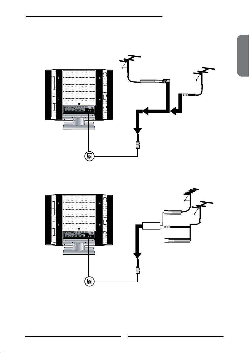
Use one of the following two diagrams when connecting an outdoor antenna.
A: Shows how to use a VHF/UHF combination outdoor antenna.
B: Shows how to use a separate VHF and/or UHF outdoor antenna.
A. Combination VHF/UHF antenna
VHF/UHF
Antenna
300-ohm twin-
lead cable
300/75-ohm adapter
(not included)
B. Separate VHF and/or UHF antennas
75-ohm
coaxial cable
VHF/UHF
Antenna
ENGLISH
UHF
Antenna
Combiner
(not included)
300-ohm twin-
lead cable
75-ohm
coaxial cable
300-ohm twin-
lead cable
VHF
Antenna
15
Page 17
Chapter 2 Installing the LCD TV
A
IN
B
OU T
Cable TV (CATV) Connection
This reminder is provided to call the CATV system installer’s attention to Article 820-40 of the
National Electrical Code (NEC) that provides guidelines for proper grounding and, in particular,
species that the cable ground shall be connected to the grounding system of the building
accurately, or as close to the point of cable entry as possible. Use of this TV for other than
private viewing of programs broadcasted on UHF, VHF or transmitted by cable companies for
the use of the general public may require authorization from the broadcast/cable company, and/
or program owner.
■ A 75-ohm coaxial cable connector is built into the set for easy hookup.
When connecting the 75-ohm coaxial cable to the set, connect the 75-
ohm cable into the ANT. terminal.
■ Some cable TV companies of fer premium pay channels. Since the
signals of these premium pay channels are scrambled, a cable T V
converter/descrambler is generally provided to the subscriber by the
cable TV company.
This converter/descrambler is necessary for normal viewing of scrambled channels.
(Set your TV to channel 3 or 4, typically one of these channels is used. If this is unknown,
consult your cable TV company.)
For more specic instructions on installing cable TV, consult your cable TV company.
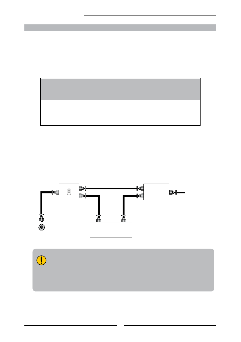
One possible method of connecting the coverter/descrambler provided by your cable TV
company is shown in the diagram below.
RF switch
(not included)
2 set signal
splitter
(not included)
Cable TV Line
Cable TV converter/
descrambler
VHF/UHF IN
■
The RF switch (not included) is required to provide two inputs (A and B). Setting
(not included)
the RF switch to position A allows viewing of all unscrambled channels by using
the TV channel keys.
■ Setting the RF switch to position B allows viewing of all scrambled channels via
the converter/descrambler by using the converter channel keys.
16
Page 18

Chapter 2 Installing the LCD TV
TV
CABLE
HDTV
AIR
VHF/UHF IN
TV
CABLE
HDTV
AIR
VHF/UHF IN
METHOD A:
Use a supplied antenna cable to connect the NTSC signal to the LCD TV’s TV CABLE
terminal.
B
ENGLISH
METHOD B:
A
Use a supplied antenna cable to connect the ATSC signal to the LCD TV’s
HDTV AIR terminal.
Connect the AC power cord at the back of the TV and connect the power cord to wall
outlet.
Press the button on the remote to turn on the LCD TV.
Always disconnect the LCD TV from the main voltage when the LCD TV will
not be used for a long period of time. The POWER button on the front panel
is only used for switching the LCD TV into standby, it does not disconnect
the device from the main voltage. To completely disconnect the main
voltage, please remove the power plug from the socket.
Press the Input button on the remote to
display the Input List. Use the ▲► buttons to
select TV( METHOD A), or HDTV (METHOD
B), and press the OK button.
Input
TV(CABLE/AIR)
HDTV (CABLE/AIR)
VIDEO1 (SIDE)
VIDEO2 (REAR)
VIDEO3 (S-VIDEO)
VIDEO4 (YPbPr1)
VIDEO5 (YPbPr2)
VIDEO6 (HDMI)
COMPUTER (VGA)
17
Page 19

HDMI IN
AUDIO
L R
L R L R
L R
L
R
L R
L R
AUDIO
VGA IN
VIDEO2 IN
VIDEO AUDIO
S-VIDEO IN
S-VIDEO AUDIO
YPbPr1 IN
AUDIO OUT
STEREO
DIGITAL
OPTICAL
COAXIAL
TV
CABLE
HDTV
AIR
VHF/UHF IN
Y Pb Pr AUDIO
YPbPr2 IN
Y Pb Pr AUDIO
Chapter 2 Installing the LCD TV
Connecting a VCR
Rear of TV
AUDIO Cable
S-VIDEO Cable
AV Cable
A B
METHOD A:
Use a composite cable to connect the VCR’s composite video/audio jacks to the LCD TV’s
VIDEO2 IN jacks.
METHOD B:
Use an audio cable to connect the VCR’s audio output jacks to the LCD TV’s audio
inputs. Use a S-Video cable to connect the VCR’s s-video output jack to the LCD TV’s
S-VIDEO IN input jack.
Connect all AC power sources, before turning on the power switch of the LCD TV or
other connected equipment.
Press the button on the remote to turn on the LCD TV.
To watch a videotape, press the Input button on the remote to select
VIDEO2( METHOD A), or VIDEO3 (METHOD B).
18
Page 20

HDMI IN
AUDIO
L R
L R L R
L R
L
R
L R
L R
AUDIO
VGA IN
VIDEO2 IN
VIDEO AUDIO
S-VIDEO IN
S-VIDEO AUDIO
YPbPr1 IN
AUDIO OUT
STEREO
DIGITAL
OPTICAL
COAXIAL
TV
CABLE
HDTV
AIR
VHF/UHF IN
Y Pb Pr AUDIO
YPbPr2 IN
Y Pb Pr AUDIO
L
R
VIDEO1 IN
VIDEO
AUDIO
Connecting a Video Camera or Play Station
PLAY STATION
Chapter 2 Installing the LCD TV
Rear of TV
Right Side
or
AUDIO Cable
S-VIDEO Cable
B
AV Cable
A
METHOD A:
Use a composite cable to connect the video camera’s or play station’s composite video/
audio jacks to the LCD TV’s VIDEO2 IN jacks or VIDEO1 IN jacks.
METHOD B:
Use an audio cable to connect the video camera’s or play station’s audio output jacks to
the LCD TV’s audio inputs. Use a S-Video cable to connect the video camera’s or play
station’s s-video output jack to the LCD TV’s S-VIDEO IN input jack.
ENGLISH
Connect all AC power sources, before turning on the power switch of the LCD TV or
other connected equipment.
Press the button on the remote to turn on the LCD TV.
To watch a video vis camera or play station, press the Input button on the remote to
select VIDEO2/VIDEO1( METHOD A), or VIDEO3 (METHOD B).
Not all cameras have the ability to connect to a TV. Please check your video camera
user guide for compatibility.
19
Page 21

HDMI IN
AUDIO
L R
L R L R
L R
L
R
L R
L R
AUDIO
VGA IN
VIDEO2 IN
VIDEO AUDIO
S-VIDEO IN
S-VIDEO AUDIO
YPbPr1 IN
AUDIO OUT
STEREO
DIGITAL
OPTICAL
COAXIAL
TV
CABLE
HDTV
AIR
VHF/UHF IN
Y Pb Pr AUDIO
YPbPr2 IN
Y Pb Pr AUDIO
Chapter 2 Installing the LCD TV
DVD P LA YER
PrPb
PrPb
Connecting a DVD Player
AV Cable
Rear of TV
or
COMPONENT/AUDIO Cable
AUDIO Cable
S-VIDEO Cable
A
B
C
METHOD A:
Use a composite cable to connect the DVD player’s composite video/audio jacks to the LCD
TV’s VIDEO2 IN jacks.
METHOD B:
Use an audio cable to connect the DVD player’s audio output jacks to the LCD TV’s
audio inputs. Use a S-Video cable to connect the DVD player’s s-video output jack to the
LCD TV’s S-VIDEO IN input jack.
METHOD C:
Use a component cable to connect the DVD player’s component output jacks to the LCD TV’s
YPbPr1 IN or YPbPr2 IN input jacks.
Use an audio cable to connect the DVD player’s component audio jacks to the LCD TV’s
audio input jacks.
The component video jacks on your DVD player are sometimes labeled
YPbPr, or YCbCr. For an explanation of component video, see your DVD
player’s user guide.
20
Page 22

Chapter 2 Installing the LCD TV
Connect all AC power sources, before turning on the power switch of the LCD TV or
other connected equipment.
Press the button on the remote to turn on the LCD TV.
To watch a DVD, press the Input button on the remote to select
VIDEO2( METHOD A), or VIDEO3 ( METHOD B), or VIDEO4/VIDEO5 (METHOD C).
For best picture quality, if your equipment has component video output, use
a component cable instead of a composite video or S-video cable.
ENGLISH
21
Page 23

Chapter 2 Installing the LCD TV
HDMI IN
AUDIO
L R
L R L R
L R
L
R
L R
L R
AUDIO
VGA IN
VIDEO2 IN
VIDEO AUDIO
S-VIDEO IN
S-VIDEO AUDIO
YPbPr1 IN
AUDIO OUT
STEREO
DIGITAL
OPTICAL
COAXIAL
TV
CABLE
HDTV
AIR
VHF/UHF IN
Y Pb Pr AUDIO
YPbPr2 IN
Y Pb Pr AUDIO
PrPb
PrPb
Connecting a Digital TV Cable Box or Digital Satellite Receiver
Rear of TV
or
COMPONENT/AUDIO Cable
Use a component cable to connect the satellite receiver’s/TV Cable Box’s component
(YPbPr1) output jacks to the LCD TV’s component input jacks.
Use an audio cable to connect the satellite receiver’s/TV Cable Box’s component audio
jacks to the LCD TV’s audio input jacks.
Connect all AC power sources, before turning on the power switch of the LCD TV or
other connected equipment.
Press the button on the remote to turn on the LCD TV.
To watch programs via satellite receiver or TV Cable Box, press the Input button on the
remote to select VIDEO4/VIDEO5.
22
Page 24

HDMI IN
AUDIO
L R
L R L R
L R
L
R
L R
L R
AUDIO
VGA IN
VIDEO2 IN
VIDEO AUDIO
S-VIDEO IN
S-VIDEO AUDIO
YPbPr1 IN
AUDIO OUT
STEREO
DIGITAL
OPTICAL
COAXIAL
TV
CABLE
HDTV
AIR
VHF/UHF IN
Y Pb Pr AUDIO
YPbPr2 IN
Y Pb Pr AUDIO
Connecting an AV Equipment with HDMI Connector
AV EQUIPMENT
Chapter 2 Installing the LCD TV
HDMI Cable
Rear of TV
ENGLISH
Use a HDMI cable to connect the AV equipment’s HDMI output jack to the LCD TV’s HDMI IN
jacks.
Connect all AC power sources, before turning on the power switch of the LCD TV or
other connected equipment.
Press the button on the remote to turn on the LCD TV.
Press the Input button on the remote to select VIDEO6.
The HDMI connector provides both video and audio signals, it’s not
necessary to connect the audio cable.
23
Page 25

Chapter 2 Installing the LCD TV
HDMI IN
AUDIO
L R
L R L R
L R
L
R
L R
L R
AUDIO
VGA IN
VIDEO2 IN
VIDEO AUDIO
S-VIDEO IN
S-VIDEO AUDIO
YPbPr1 IN
AUDIO OUT
STEREO
DIGITAL
OPTICAL
COAXIAL
TV
CABLE
HDTV
AIR
VHF/UHF IN
Y Pb Pr AUDIO
YPbPr2 IN
Y Pb Pr AUDIO
AV EQUIPMENT
DVI IN
AUDIO
L R
Connecting an AV Equipment with DVI Connector
Rear of TV
AUDIO Cable
HDMI-to-DVI Cable
Use a HDMI-to-DVI cable to connect the AV equipment’s DVI output jack to the LCD TV’s
HDMI IN jacks.
Use an audio cable to connect the AV equipment’s audio output jacks to LCD TV’s HDMI
AUDIO jacks.
Connect all AC power sources, before turning on the power switch of the LCD TV or
other connected equipment.
Press the button on the remote to turn on the LCD TV.
Press the Input button on the remote to select VIDEO6.
If the LCD TV is connected to AV equipment’s DVI connector, you will need
an HDMI-to-DVI cable or an HDMI adapter(not suplied).
24
Page 26

HDMI IN
AUDIO
L R
L R L R
L R
L
R
L R
L R
AUDIO
VGA IN
VIDEO2 IN
VIDEO AUDIO
S-VIDEO IN
S-VIDEO AUDIO
YPbPr1 IN
AUDIO OUT
STEREO
DIGITAL
OPTICAL
COAXIAL
TV
CABLE
HDTV
AIR
VHF/UHF IN
Y Pb Pr AUDIO
YPbPr2 IN
Y Pb Pr AUDIO
Connecting a PC
PC
Chapter 3 Using the LCD TV
AUDIO Cable
VGA Cable
Rear of TV
ENGLISH
Use a D-SUB cable to connect the PC’s D-SUB output jack to the LCD TV’s VGA input
jack. Use an audio cable to connect the PC’s audio output jacks to LCD TV’s.
Connect all AC power sources, before turning on the power switch of the LCD TV or
other connected equipment.
Press the button on the remote to turn on the LCD TV.
Press the Input button on the remote to select COMPUTER.
25
Page 27

Audio Receiver
Audio Amplifier
Chapter 3 Using the LCD TV
HDMI IN
AUDIO
L R
L R L R
L R
L
R
L R
L R
AUDIO
VGA IN
VIDEO2 IN
VIDEO AUDIO
S-VIDEO IN
S-VIDEO AUDIO
YPbPr1 IN
AUDIO OUT
STEREO
DIGITAL
OPTICAL
COAXIAL
TV
CABLE
HDTV
AIR
VHF/UHF IN
Y Pb Pr AUDIO
YPbPr2 IN
Y Pb Pr AUDIO
Connecting an Audio Receiver or a Dolby Digital 5.1 Sound System
For better sound quality, you may want to play the LCD TV audio through your stereo system.
AUDIO Cable
AB
Connecting to Audio Receiver:
Use an audio cable to connect the audio receiver’s audio LINE IN jacks to LCD TV’s
AUDIO OUT jacks.
Connecting to Digital 5.1 Sound System:
METHOD A:
Use an optical cable to connect the audio amplier’s OPTICAL IN jacks to LCD TV’s
OPTICAL OUT jacks.
METHOD B:
Use a coaxial cable to connect the audio amplier’s COAXIAL IN jacks to LCD TV’s
COAXIAL OUT jacks.
Note: Above mentioned function is only available under HDTV (cable/air) mode.
Connect all AC power sources, before turning on the power switch of the LCD TV or
other connected equipment.
Press the button on the remote to turn on the LCD TV.
26
Page 28

Chapter 3 Using the LCD TV
Chapter 3
USING THE FEATURES
Using Picture-In-Picture
The PIP/POP feature allows simultaneous viewing of video from two sources (TV, VCR, DVD etc).
Only one source’s audio is played at a time; the user may select which source’s audio is heard.
Press the PIP button once to enter picture in picture mode.
Main
Sub
ENGLISH
▪ Press ◄ ► to toggle the audio source between the main window and
▪ Press the OK button to change the position of the second window.
the sub window.
1
MAINSUB
2
3
5
▪ Press ◄ ► to activate either the main or sub window, then press the Input
▪ Press ▲▼ to change input source and press the OK button.
button to display the Input List:
Sub
TV(CABLE/AIR)
VIDEO1 (SIDE)
VIDEO2 (REAR)
VIDEO3 (S-VIDEO)
VIDEO4 (YPbPr1)
VIDEO5 (YPbPr2)
COMPUTER (VGA)
4
27
Page 29

Chapter 3 Using the LCD TV
Press the PIP button again to view images side by side.
SubMain
▪ Press ◄ ► to toggle the audio source between the main window and the sub window.
▪ Press the OK button to swap the pictures between the main and sub windows.
▪ Press ◄ ► to activate either the main or sub window, then press the Input button to
display the Input List:
Sub
TV(CABLE/AIR)
VIDEO1 (SIDE)
VIDEO2 (REAR)
VIDEO3 (S-VIDEO)
VIDEO4 (YPbPr1)
VIDEO5 (YPbPr2)
COMPUTER (VGA)
Press ▲▼ to change input source and press the OK button.
Press the PIP button again to exit.
28
Page 30

Wide Screen Viewing
Chapter 3 Using the LCD TV
Wide Screen function allows viewing of 4:3/16:9 images in wide screen mode, cycling through
the following wide screen settings. Press the ASPECT button repeatedly to select the screen
format you want.
NORMAL
Displays at 4:3 aspect ratio.
FULL
Stretches the image vertically and
horizontally to keeps the image size
consistent in the center of the screen and
stretches the sides
WIDE
Stretches the image vertically and
horizontally to ll the screen at 1:1.85
aspect ratio.
ENGLISH
ZOOM
Stretches the image vertically and
horizontally to ll the screen at 1:2.35
aspect ratio.
29
Page 31

Chapter 3 Using the LCD TV
Operating the Menu
Press the button to turn the LCD TV on.
Press the MENU button on the remote control,the on-screen menu will appear on the
screen. Use the ◄► buttons to select your main menu option.
VIDEO MENU:
Allows you to make adjustments to your picture settings.
▪ If the signal source is VGA, the VIDEO MENU
appears as:
▪ If the signal source is TV/HDTV/VIDOE/SVIDEO/
YPbPr/HDMI, the VIDEO MENU appears as:
Picture Mode Vivid
Contrast 75
Brightness 65
Auto Setting
Phase 20
Manual Clock 128
Display Adjustment
Color Temperature Nature
Video Select Exit
AUDIO MENU:
Allows you to customize the audio options and effects.
▪ If the signal source is VIDOE/SVIDEO/YPbPr/
HDMI/VGA, the AUDIO MENU appears as:
Bass 50
Treble 50
Balance 0
Sound Effect Off
Audio Select Exit
▪ If the signal source is HDTV, the AUDIO MENU appears as:
Bass 50
Treble 50
Balance 0
Sound Effect Off
Picture Mode Vivid
Contrast 75
Brightness 55
Saturation 62
Hue +22
Sharpness 4
Color Temperature Nature
Video Select Exit
▪ If the signal source is TV, the AUDIO MENU
appears as:
Bass 50
Treble 50
Balance 0
Sound Effect Off
MTS System Stereo
Audio Select Exit
Audio Select Exit
30
Page 32

Chapter 3 Using the LCD TV
SETUP MENU:
Allows you to set up a variety of features: Language, Closed Caption, factory reset, V-Chip, Parental Control
sleep timer.
Language English
Timer 15
Closed Caption off
V-Chip
Parental
Default
Setup Select Exit
TV MENU:
Allows you to edit and label channels.
Searching
Tuner Mode Cable-STD
Channel Skip On
Channel Name
TV Select Exit
ENGLISH
HDTV MENU:
Allows you to set up the HDTV program function.
Audio Language ◄ English ►
Time Zone Eastern Time
SPDIF Type PCM
Auto Scan Scan
Manual Scan Press<Enter>
Channel Skip Press<Enter>
Channel Block Press<Enter>
Caption Press<Enter>
HDTV Select Exit
Use the ▲▼ buttons to select an option of the sub-menu, and press the OK button. While in
adjustment mode, and use the ◄► buttons to change the value of the item.
Press the MENU button to exit the menu.
31
Page 33

Chapter 3 Using the LCD TV
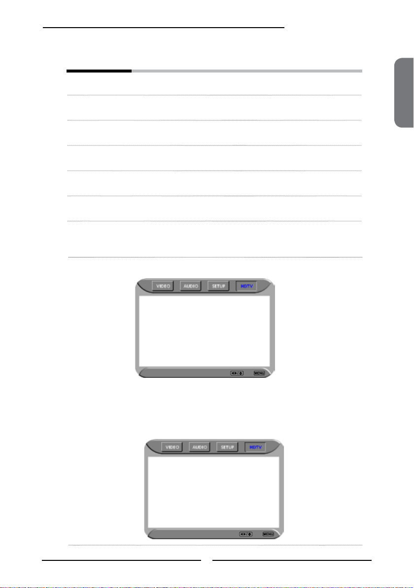
Setting up the HDTV Function
Automatically scans and stores all the TV channels
With the LCD TV connected to a television programming source, press the TV button
on the remote control.
Press the MENU button on the remote control to display the Main menu, and use
the ◄► buttons to select the HDTV.
Audio Language ◄ English ►
Time Zone Eastern Time
SPDIF Type PCM
Auto Scan Scan
Manual Scan Press<Enter>
Channel Skip Press<Enter>
Channel Block Press<Enter>
Caption Press<Enter>
HDTV Select Exit
Press the ▼ button to select Auto Scan, and press the OK button. The Auto Scan
automatically creates a list of receivable channels. Press the MENU button at any time to
interrupt the memorization process.(the list cannot be created if interrupted)
Status: Scanning..
Channels Found: 2
HDTV Cancel
Press the OK button to display the received channel list, then press ▲▼the buttons to
select a channel. Or, use the ▪ (Input button) with 0-9 buttons to select digital channel( for
example 9.1)
Channel List
9-1 KQED-HD
9-2 KOED-SD
The digital main channel might include many subchannels (for example
9-1, 9-2..) that are showing program at the same time.
32
Page 34
The HDTV menu includes the following options:
Chapter 3 Using the LCD TV
Audio Language Allows to select the audio language:
English/Spanish/French.
Time Zone Allows selection of regional TV systems of USA: Eastern Time/Indiana/
Central time/Mountain Time/Arizona/Pacic Time/Alaska/Hawaii
SPDIF Type Allows to selection of the digital sound format: PCM/OFF/Dolby Digital
Auto Scan Automatically sets up channel list on TV for all receivable channels.
Manual Scan Allows to set up TV channel manually.
Channel Skip Allows addition/removal of digital channels.
Channel Block Allows to block digital channels.
Use the Channel Block function, must enter a four-digit password. The
factory password is 0000.
Caption Allows to set closed caption:
Analog Closed Caption ◄ OFF ►
Digital Closed Caption OFF
Caption Style
ENGLISH
▪ Analog Closed Caption:
HDTV Select Back
Allows to set basic analog closed caption options:OFF/CC1/CC2/CC3/CC4
▪ Digital Closed Caption:
Allows to set digital closed caption options:Service1/Service2/Service3/
Service4/Service5/Service6/OFF
▪ Caption Style:
Allows to customize the settings for digital closed caption option:
Caption Style ◄ Custom ►
Font Size Large
Font Color White
Font Opacity Solid
Background Color Black
Background Opacity Solid
Window Color Black
Window Opacity Translucent
HDTV Select Back
33
Page 35

Chapter 3 Using the LCD TV
Using the Program Guide
The Program Guide feature brings all sorts of information provided by the cable TV
company to your screen, such as program title, program duration, time remaining, rating
information, closed caption, availability, etc.
With the LCD TV connected to a television programming source, press the TV button on the
remote control.
Press the GUIDE button on the remote control, the Program Guide will appear on the
screen:
9-1 ◄ 9-2 KQED-SD ► 9-1
Today 5:00 PM Calfornia’s Gold CC
Today 5:30 PM Antiques Roadshow
Today 6:00 PM The NewHour with Jim Lehrer CC
Today 7:30 PM Zoboomafoo CC
Today 7:30 PM Arthur
Today 11:00 PM Antiques Roadshow CC
5:00 PM - 5:30 PM Mon, 29 Apr Not Rated
Clubs: Dongwa doesn’t communicate with his parents.
Eplisode: Explorer’s club/Time for everything
9 - 2 KOED-SD
Monday 29 April 2005 2:36:26 PM
Press the ▲▼ button to select the program from a list, the Program Guide provides
introduction about the current program being shown on each channel.
Monday 29 April 2005 2:36:26 PM
9-1 ◄ 9-2 KQED-SD ► 9-1
Today 5:00 PM Calfornia’s Gold CC
Today 5:30 PM Antiques Roadshow
Today 6:00 PM The NewHour with Jim Lehrer CC
Today 7:30 PM Zoboomafoo CC
Today 7:30 PM Arthur
Today 11:00 PM Antiques Roadshow CC
5:00 PM - 5:30 PM Mon, 29 Apr Not Rated
Clubs: Dongwa doesn’t communicate with his parents.
Eplisode: Explorer’s club/Time for everything
9 - 2 KOED-SD
Press the GUIDE button again on the remote control to exit the Program Guide
34
Page 36

Chapter 3 Using the LCD TV
Customizing the VIDEO Settings
Press the button to turn the LCD TV on.
Press the MENU button on the remote control to display the Main menu, and use the
◄► buttons to select the VIDEO.
Use the ▲▼buttons to highlight an individual VIDEO option, use the ◄► buttons to
change the setting, and press the MENU to exit the menu
Picture Mode Vivid
Contrast 75
Brightness 55
Saturation 62
Hue +22
Sharpness 4
Color Temperature Nature
Video Select Exit
The VIDEO menu includes the following options:
Picture Mode Cycles among display types: Vivid/Hi-Bright/Cinema/Sport/User
ENGLISH
Contrast Controls the difference between the brightest and darkest regions of the
Brightness Controls the overall brightness of the picture.
Saturation Controls the color intensity.
Hue Controls the difference between the green and red regions of the
Sharpness Increase this setting to see crisp edges in the picture; decrease it for
Color temperature Adjusts color components independently to achieve a warm or cool
▪ Warm: Increases red tint
▪ Nature: Increases natural tint
▪ Cool: Increases blue tint
▪ User: Allows the user to adjust red, green and blue color
component levels independently.
picture.
picture.
soft edges.
effect: Cool/Middle/Warm/User
35
Page 37

Chapter 3 Using the LCD TV
Customizing the AUDIO Settings
Press the button to turn the LCD TV on.
Press the MENU button on the remote control to display the Main menu, and use the
◄► buttons to select the AUDIO.
Use the ▲▼buttons to highlight an individual AUDIO option, use the ◄► buttons to
change the setting, and press the MENU to exit the menu
Bass 50
Treble 50
Balance 0
Sound Effect Off
MTS System Stereo
Video Select Exit
The AUDIO menu includes the following options:
Bass Controls the relative intensity of lower-pitched sounds.
Treble Controls the relative intensity of higher pitched sounds.
Balance Adjusts the relative volume of the speakers in a multiple speaker
Sound Effect Allows selection of an audio-enhancement technique from among the
MTS System Allows you to listen to high-delity stereo sound while watching TV.
▪ Stereo:
Use separate audio tracks for left and right speakers, if available.
▪ SAP:
You can enjoy a second audio program from the speakers while
▪ Mono:
Allows mono output (useful when stereo is noisy or inconsistent).
system.
following options: Surround/Live/Dance/Techno/Classic/Soft/Rock/POP/
Off.
watching a scene in the original program.
36
Page 38

Chapter 3 Using the LCD TV
Customizing the SETUP Settings
Press the button to turn the LCD TV on.
Press the MENU button on the remote control to display the Main menu, and use the
◄► buttons to select the SETUP.
Use the ▲▼buttons to highlight an individual SETUP option, use the ◄► buttons to
change the setting, and press the MENU to exit the menu.
Language English
Timer 15
Closed Caption off
V-Chip
Parental
Default
Video Select Exit
The SETUP menu includes the following options:
Language Selects to display all on-screen menus in your language of choice:
English/Trandition Chinese/Simplied Chinese/French/Spanish.
ENGLISH
Timer Allows to set up clock and to program the TV to turn on and off and tune
▪ Time:
Selects to set the current time by hour, minute, second.
▪ Start Time:
Selects to set the time that you want the TV to turn on.
▪ Stop Time:
Selects to set the time that you want the TV to turn off.
▪ Channel:
Selects to set the specic channel that you want the TV to tune.
▪ Activate:
Selects to turn on/off/once the timer.
▪ Confirm:
Selects to conrm.
to a specic channel.
37
Page 39

Chapter 3 Using the LCD TV
Closed Caption Allows to select from 4 closed caption modes:
▪ CC1 /CC2 /CC3 /CC4:
Display a printed version of the dialog and sound effects of the
program being viewed.
▪ T1/T2:
Display station information presented using either half or the whole
screen.
▪ T3/T4:
Extended Data Services. For example: Network name, program
name, program length, etc.
V-Chip Allows to setup the TV and MPAA Rating Lock options(refer to “Using the
V-CHIP Setting”).
Parental Allows to setup the Parental Lock options.
Default Restores factory settings.
38
Page 40

Using the V-CHIP Settings
Chapter 3 Using the LCD TV
The US has 2 rating system for viewing content: Movie blocking(MPAA) and TV Blocking.
The TV Blocking conjuncts with the V-CHIP to help parents block inappropriate programs from their
children.
The Movie blocking(MPAA) is used for original movies rated by the Motion Picture Association of
America(MPAA) as broadcasted on cable TV and not edited for television.
The V-CHIP can also be set to block MPAA-rated movies.
Use the ▼ button to select the V-Chip, and press the OK to display the V-Chip menu.
Block MPAA Rating
Block TV Rating
Block MPAA Unrated No
Block TV None Rating No
Setup Select Exit
Use the V-CHIP function, must enter a four-digit password. The factory password is
0000.
Inout Your Password Please
* * * *
OK Cancel
ENGLISH
The MPAA includes the following options:
RATING DESCRIPTION
G General Audiences. Movie is appropriate for all ages.
PG Parental Guidance Suggested. May contain material not suited for younger
PG-13 Contains content that may not be appropriate for viewers under the age of 13.
R Restricted. Contains adult content, no one under 17 admitted without parent.
NC-17 No one 17 and under admitted.
X No one 17 and under admitted.
Use the ▲▼ buttons to select the rating you want and press the OK button repeatedly to select
BLOCK() or UNBLOCK().
viewers
39
Page 41

Chapter 3 Using the LCD TV
The TV GUIDELINE has 2 rating methods: Content- Based Rating and Age-Based Rating.
The
AGE-BASED
RATING DESCRIPTION
TV-Y All children
TV-Y7 Directed to children age 7 and older
TV-G General Audience
TV-PG Parental Guidance suggested
TV-14 Parents strongly cautioned
TV-MA Mature Audience only
TV GUIDELINE includes the following options:
FV D L S V
TV-Y
TV-Y7
TV-G
TV-PG
AGE-BASED
TV-14
TV-MA
: To block programs by both content and age.
CONTENT-BASED
RATING DESCRIPTION
FV Fantasy violence
D Suggestive dialogue
L Strong language
S Sexual situations
V Violence
CONTENT-BASED
Use the ▲▼ buttons to select the rating you want and press the OK button repeatedly to select
BLOCK() or UNBLOCK().
The V-CHIP menu includes the following options:
Block MPAA Rating Selects to activate the MPAA Rating programs
Block TV Rating Selects to activate the TV Rating programs.
Block MPAA Unrated ▪ YES:
Block all movies that are broadcast without a MPAA rating.
▪ NO:
Allows all movies that are broadcast without a MPAA rating
Block TV None Rating ▪ YES:
Block all movies that are broadcast without a TV rating.
▪ NO:
Allows all movies that are broadcast without a TV rating.
40
Page 42

Using the Parental Settings
Chapter 3 Using the LCD TV
The Parental blocking can be set up to the TV to block a Channel or a Video Source.
Use the ▼ button to select the Parental, and press the OK to display the Parental
menu.
Channel Lock 1
Video Lock VIDEO5(YPbPr2)
Change Password
Setup Select Exit
Use the V-CHIP function, must enter a four-digit password. The factory password is
0000.
Inout Your Password Please
* * * *
OK Cancel
You need your password for any future access into the V-Chip and
Parental Setting,
ENGLISH
The Parental menu includes the following options:
Channel Lock Selects to block a TV channel.
Video Lock Selects to block a Input source signal.
Change Password Selects to change your password.
41
Page 43

Chapter 3 Using the LCD TV
Customizing the TV Settings
Press the button to turn the LCD TV on.
Press the MENU button on the remote control to display the Main menu, and use the
◄► buttons to select the TV.
Use the ▲▼buttons to highlight an individual TV option, use the ◄► buttons
changes the setting, and press the MENU exits the menu.
Searching
Tuner Mode Cable-STD
Channel Skip On
Channel Name
TV Select Exit
The TV menu includes the following options:
Searching Automatically sets up channel list on TV for all receivable channels.
Tuner Mode Allows selection between CATV cable and antenna signal sources:
▪ ANTENNA
Choose this setting if you are receiving TV channels with an antenna
▪ CABLE STD/CABLE IRC/CABLE HRC
Choose this setting if you are receiving TV channels with a CATV
Channel Skip Allows addition/removal of channels on the channel list.
Channel Name Allows channel labels to be edited.
cable.
cable.
42
Page 44

SPECIFICATIONS
Specifications
ENGLISHENGLISHENGLISH
MODEL
LCD Panel Panel Size 26’’ TFT LCD 32’’ TFT LCD
Brightness 550 500
Contrast Ratio 1000:1 800:1
Max. Resolution 1366x768 1366x768
Input Connector VIDEO/AUDIO(L/R) 2 2
S-VIDEO/AUDIO(L/R) 1 1
YPbPr/AUDIO(L/R) 2 2
VGA/AUDIO(L/R) 1 1
HDMI/AUDIO(L/R) 1 1
AUDIO OUT(L/R) 1 1
OPTICAL/COAXIAL 1 1
HEADPHONE 1 1
Power Source AC100~240V, 50/60HZ, 2.2A AC100~240V, 50/60HZ, 2.2A
Power Consumption 180 W, standby < 5 W 180 W, standby < 5 W
Dimension 26.7 w x 22.1 h x 7.9 d inch 31.7 w x 25.0 h x 8.4 d inch
WEIGHT 31.97 LB 39.5 LB
FLM-2632/FLM-263B FLM-3232/FLM-323B
43
Page 45

Specifications
MODEL
FLM-3732/FLM-373B
LCD Panel Panel Size 37’’ TFT LCD
Brightness 500
Contrast Ratio 1000:1
Max. Resolution 1366x768
Input Connector VIDEO/AUDIO(L/R) 2
S-VIDEO/AUDIO(L/R) 1
YPbPr/AUDIO(L/R) 2
VGA/AUDIO(L/R) 1
HDMI/AUDIO(L/R) 1
AUDIO OUT(L/R) 1
OPTICAL/COAXIAL 1
HEADPHONE 1
Power Source AC100~240V, 50/60HZ, 3.0A
Power Consumption 275 W, standby < 8 W
Dimension 36.6 w x 28.2 h x 9.4 d inch
WEIGHT 54 LB
44
Page 46

Chapter 4
Programming your Remote Control
Introduction
Your remote lets you control four devices with one easy-to-use, compact unit. After installing batteries, you can program the
remote to control your Universal TV, VCR or DVD, Cable or Satellite Receivers, Amplifier or Tuner, and Auxiliary devices. To
do so, follow the instructions in “Programming a Device”. For best results, please read and follow all the remaining
instructions. Keep this guide for future reference.
A Quick Look at Programming a Device
To control VCR or DVD, Cable or Satellite Receivers, Amplifier or Tuner, and Auxiliary devices, follow these steps. Before
proceeding, find the codes for the devices you want to program in “Manufacturer’s Codes” on the right side of this page and
write them down or highlight them.
NOTE: To program a DVD Player, TV/DVD Combo, TV/VCR/DVD Combo, portable DVD player, or mobile DVD player, use
the DVD key.
1. Turn on the device (for example, DVD player) and, if needed, load media (for example, a DVD).
2. Press a device key (VCR/DVD, CBL/ SAT, or AUX).
3. Press and hold SET until the red LED blinks twice; then release.
4. Enter the first five-digit code for your device. The LED blinks once as each digit is entered. If the code is correct,
the LED blinks twice.
5. Aim the remote at the device and press Power. The device should turn off. If it does not, repeat steps 3–5, trying
6. Repeat steps 1–5 for the other devices you want to control. For future reference, write down each working device
7. Press set to save and exit
Searching for your Code
If your device does not respond to the remote after trying all codes listed for your brand, or if your brand is not listed, try
searching for your code:
1. Press a device key once.
2. Press and hold SET until the red LED blinks twice; then release.
3. Enter 9-9-1, then the device group number (0= Cable, 1= TV, 2= VCR, 3= Audio). The LED blinks twice.
4. Aim the remote at the device and press Power. The remote sends IR codes from its library to the selected device,
5. If the device does not respond, press CH+. The remote will try the next code. Continue until the device responds.
6. To search for other device codes, repeat steps 1 to 5.
7. Press SET to save and exit.
Checking the Codes
If you have set up the remote using the procedure in “Searching for Your Code”, you may need to find out which four-digit
code is operating your equipment.
For example, to find out which code is assigned to your TV:
1. Press TV once.
• NOTE: If the LED does not blink twice, repeat steps 2 to 4 and try entering the code again.
each code for your brand until you find one that works. If you cannot find a code that works, see “Searching for
Your Code”.
code below:
AUX Code:
CBL Code:
CD Code:
DVD Code:
SAT Code:
TNR Code:
VCR Code:
starting with the most popular code first. If the device responds, go to step 7.
• Note: Press CH- to try the previous code.
A
Page 47

2. Press and hold SET until the red LED blinks twice; then release.
3. Enter 9-9-0. The LED blinks twice.
4. To view the code for the first digit, press 1. Count the LED blinks (for example, three blinks = 3), and write down
the number in the appropriate code listing in step 8 under “Programming a Device”.
5. Repeat step 4 for the four remaining digits, using 2 for the second digit, 3 for the third digit, 4 for the fourth digit,
6. To check for other device codes, repeat steps 1—5, substituting the device key for TV.
• NOTE: If a code digit is 0, the LED does not blink.
and 5 for the fifth digit.
Changing Volume Lock
The remote comes preset to allow independent volume control of each selected device (Global Volume Unlock). However,
you may change the Volume Lock setting to Global Volume Lock so that one device's volume will control volume in all other
modes. After that, you can perform Individual Volume Unlock on a selected device to set its volume control for independent
operation or Global Volume Unlock to remove all volume locking.
Locking Volume Control to One Mode (Global Volume Lock)
1. Press and hold SET until the red LED blinks twice; then release.
2. Enter 9-9-3 and then press the mode key for the device you want to control volume (for example, TV). The LED
blinks twice. Now when you press VOL+, VOL-, or Mute, the selected device (for example, TV) will control the
volume regardless of the current mode.
Unlocking All Volume Control (Restoring Global Unlock)
1. Press and hold SET until the red LED blinks twice; then release.
2. Enter 9-9-3 and then press VOL+. The LED blinks four times.
Volume is now independently controlled for all programmed devices.
Unlocking a Single Device’s Volume Control
1. Press a device key (TV, VCR/DVD, CBL/ SAT, or AUX).
2. Press and hold SET until the red LED blinks twice; then release.
3. Enter 9-9-3 and then press VOL-. The LED blinks four times.
Volume is now independently controlled for the selected devices.
Troubleshooting
PROBLEM: LED does not blink when you press a key.
SOLUTION: Replace battery with one new 3.3 V 2032 Lithium battery.
PROBLEM: LED blinks when you press a key, but device does not respond.
SOLUTION: Make sure the remote is aimed at your device and is not more than 15 feet away.
PROBLEM: LED blinks one long blink.
SOLUTION: An entry error has occurred (for example, wrong key). Try entry sequence again.
PROBLEM: Remote does not control devices or commands are not working properly.
SOLUTION: Try all listed codes for the device. Make sure the device operates with an infrared remote control.
PROBLEM: CH+, CH-, and LAST do not work for your RCA TV.
SOLUTION: Due to RCA design from 1983 to 1987, only the original remote control will operate these functions.
PROBLEM: No volume on a device.
SOLUTION: See “Changing Volume Lock”.
PROBLEM: Channels do not change properly.
SOLUTION: If the original remote control required you to press Enter to change channels, press Enter on this remote after
entering the channel number.
B
Page 48

MANUFACTURER’S CODES
Set Codes for Audio Amplifiers
Bose 30674
GE 30078
JVC 30331
Marantz 30321
Nakamichi 30321
NEC 30264
Optimus 30395
Realistic 30395
Sansui 30321
Shure 30264
Sony 30689
Soundesign 30078
Victor 30331
Wards 30078
Yamaha 30354, 30133
Set Codes for Audio Amp/Tuners
ADC 30531
Aiwa 31405, 31243, 30121
Anam 31609, 31074
Audiotronic 31189
Bose 31229
Capetronic 30531
Carver 31189
Coby 31263
Denon 31360, 31142, 30904
Fonmix 31360
Glory Horse 31263
Harman/Kardon 30110
Hitachi 31273
Inkel 30027
Integra 30135
JBL 30110
JVC 30074, 31263
Kenwood 31313, 31570, 30027
KLH 31428
Magnavox 31189, 31269, 30531
Marantz 31189, 31269, 30039
MCS 30039
Onkyo 30842, 30135
Optimus 31023, 30670, 30531, 31074
Panasonic 31518, 30039
Philips 31189, 31269
Pioneer 31023, 30150, 30014, 30630, 30531
Proscan 31254
Qisheng 31609
Quasar 30039
RadioShack 31263
RCA 31023, 31609, 31254, 30531, 31074
Sharper Image 31263
Silsonic 30176
Sony 31258, 31759
Soundesign 30670
Stereophonics 31023
Sunfire 31313
Teac 31074, 31267
Technics 31308, 31518, 30039
Thorens 31189
Victor 30074
Wards 30014
Yamaha 30176, 31276, 31176
C
Page 49

Set Codes for Cable Converters
ABC 00003, 00008, 00014
Americast 00899
Bell & Howell 00014
Bell South 00899
Clearmaster 00883
ClearMax 00883
Coolmax 00883
Daeryung 01877, 00877, 00477, 00008
Digi 00637
Director 00476
Dumont 00637
Gehua 00476
General Instrument 00476, 00810, 00276, 00003, 00014
GoldStar 00144
Hamlin 00009, 00273
Hitachi 00014
Jerrold 00476, 00810, 00276, 00003, 00012, 00014
KNC 00008
LG 00144
Memorex 00000
Motorola 00476, 00810, 00276, 01254, 01376
MultiVision 00012
Pace 01877, 00237
Panasonic 00000, 00008, 00107
Panther 00637
Paragon 00000
Philips 00317, 01305
Pioneer 01877, 00877, 00144, 00533
Pulsar 00000
Quasar 00000
RadioShack 00883
Regal 00279, 00273
Runco 00000
Samsung 00000, 00144
Scientific Atlanta 01877, 00877, 00477, 00008
Sony 01006
Starcom 00003, 00014
Supercable 00276
Supermax 00883
Tocom 00012
Torx 00003
Toshiba 00000
Trans PX 00276
Tristar 00883
TS 00003
V2 00883
Viewmaster 00883
Vision 00883
Vortex View 00883
Zenith 00000, 00525, 00899
Set Codes for CD Players
Aiwa 30157
Burmester 30420
California Audio Labs 30029
Carver 30157, 30179
Denon 30873
DKK 30000
DMX Electronics 30157
Dynamic Bass 30179
Fisher 30179
Garrard 30420
Genexxa 30032
D
Page 50

Harman/Kardon 30157, 30173
Hitachi 30032
Integra 30101
JVC 30072
Kenwood 30826, 30626, 30028, 30037, 30036, 30190
Krell 30157
Linn 30157
Magnavox 30157
Marantz 30626, 30029, 30157
MCS 30029
Miro 30000
Mission 30157
MTC 30420
NSM 30157
Onkyo 30868, 30101
Optimus 31063, 30000, 30032, 30037, 30420, 30179, 31075, 30145
Panasonic 30029
Parasound 30420
Philips 30626, 30157
Pioneer 31063, 31062, 30032
Polk Audio 30157
Proton 30157
QED 30157
Quad 30157
Quasar 30029
RadioShack 31075
RCA 31062, 30032, 30420, 30179, 30053
Realistic 30420, 30179
Rotel 30157, 30420
SAE 30157
Sansui 30157
Sanyo 30179
SAST 30157
Sharp 30861, 30037
Silsonic 30888, 30036
Sonic Frontiers 30157
Sony 30490, 30000, 30100
Soundesign 30145
TAG McLaren 30157
Tascam 30420
Teac 30420
Technics 30029
Victor 30072
Wards 30157, 30053
Yamaha 30888, 30036
Zonda 30157
Set Codes for DVD Players
Aiwa 20641, 21912
Akai 20770
Allegro 20869
Apex Digital 20672, 20717, 20797, 21061, 20796, 21056, 21937, 20794, 21020, 21915
Blaupunkt 20717
Blue Parade 20571
Broksonic 20695
Changhong 20627, 21061
CineVision 20869
Coby 21086
Curtis Mathes 21087
CyberHome 21024, 21023, 21129, 20816, 21117
Daewoo 20833, 21172, 20869
Denon 20490
DVD2000 20521
E
Page 51

Emerson 20591, 20675
Enterprise 20591
Fisher 21919
Funai 20675
Gateway 21158, 21073
GE 20522, 20717
Go Video 20744, 20833, 21099, 20783, 21075, 20869, 21730
Greenhill 20717
Harman/Kardon 20582, 20702
Hitachi 20573, 20664, 21919
Hiteker 20672
Initial 20717
Integra 20627, 21924
JBL 20702
JVC 20558, 20623, 20867
Kenwood 20490, 20534
KLH 20717, 21020, 21149
Koss 20651, 21980
Lasonic 20798
LG 20591, 20869, 20801
Liquid Video 21980
Lite-On 21158, 21058
Loewe 20511
Magnavox 20503, 20539, 21976, 21914, 20675
Marantz 20539
Memorex 20695
Microsoft 20522
Mintek 20717
Mitsubishi 21521, 20521
Nesa 20717
Norcent 21003
Onkyo 20503, 20627, 21924, 20792
Oritron 20651, 21980
Panasonic 20490, 21762, 21990
Philips 20503, 20539, 20646, 21914
Pioneer 20525, 20571
Polaroid 21086, 21061
Polk Audio 20539
Portland 20770
Proscan 20522
Qwestar 20651
RCA 20522, 20571, 20717, 20822
Rio 20869
Rotel 20623
Sampo 20752, 20698
Samsung 20490, 20573, 21932, 21075, 20820
Sansui 20695
Sanyo 20695
Sharp 20630, 20752
Sharper Image 21117
Sherwood 20770
Shinco 20717
Shinsonic 20533
Sonic Blue 20869, 21099
Sony 20533, 20864, 21033, 21904, 21903
SVA 20717
Sylvania 20675
Symphonic 20675
Teac 20717, 21984, 20809
Technics 20490
Theta Digital 20571
Toshiba 20503, 20695
Urban Concepts 20503
Xbox 20522
Yamaha 20490, 20539, 20545
Zenith 20503, 20591, 20869
F
Page 52

Set Codes for Satellite Receivers
AlphaStar 00772
Chaparral 00216
Crossdigital 01109
DirecTV 00392, 00566, 00639, 01142, 00247, 00749, 01749, 00724, 00819, 01856, 01076, 01109,
00099, 01392,
Dish Network System 01005, 00775, 01505
Dishpro 01005, 00775, 01505
Echostar 01005, 00775, 01505
Expressvu 00775
GE 00566
General Instrument 00869
GOI 00775
Goodmans 01246
Hisense 01535
Hitachi 00819, 00222, 01250
HTS 00775
Hughes Network Systems 01142, 00749, 01749, 01442
I-Lo 01535
JVC 00775
LG 01414, 01226
Magnavox 00724, 00722
Memorex 00724
Mitsubishi 00749
Motorola 00869
NEC 01270
Next Level 00869
Panasonic 00247, 00701
Paysat 00724
Philips 01142, 00749, 01749, 00724, 01076, 00722, 00099, 01442
Proscan 00392, 00566
Proton 01535
RadioShack 00869
RCA 00392, 00566, 00855, 00143, 01392
Samsung 01276, 01109, 01108
Sanyo 01219
SKY 00856
Sony 00639, 01640
Star Choice 00869
Tivo 01142, 01442
Toshiba 00749, 01749, 00790, 01285
UltimateTV 01640, 01392
Uniden 00724, 00722
US Digital 01535
USDTV 01535
Voom 00869
Zenith 00856, 01856
01640, 01442, 01414, 01108
Set Codes for TVs
Addison 10092
Admiral 10093, 10463
Advent 10761, 10842
Aiko 10092
Aiwa 11914
Akai 10812, 10702, 10030, 10672, 11903
Albatron 10700, 10843
America Action 10180
Anam 10250, 10180, 10700
Anam National 10250, 10650
Anhua 10051
AOC 10451, 10093, 10180, 10060, 10030, 10178, 10092
Apex Digital 10748, 10765, 10879, 10767, 11943
G
Page 53

Audiovox 10451, 10180, 10875, 10092, 10623
Baile 10661
Beijing 10812, 10661
Bell & Howell 10154
BenQ 11032
Bradford 10180
Broksonic 10236, 10463, 11911, 11938, 11905, 11935, 11929
Cailing 10748
Candle 10030
Carnivale 10030
Carver 10054
Celebrity 10000
Celera 10765
Changcheng 10051, 10661
Changhong 10156, 10765, 11156, 10767
Ching Tai 10092
Chun Yun 10000, 10180, 10700, 10092, 10843
Chung Hsin 10180, 10053
Cinema 10672
Citizen 10180
Commercial Solutions 11447, 10047
Conrowa 10156, 10145, 11156
Contec 10180
Craig 10180
Crosley 10054
Crown 10180
Curtis Mathes 10047, 10054, 10154, 10451, 10093, 10060, 10702, 10030, 10145, 10166
CXC 10180
Daewoo 10154, 10451, 10180, 10030, 10178, 10672, 11928, 10092, 10661, 11909, 10623, 10700
Dayu 10661
Dell 11080
Denon 10145
Dumont 10017
Durabrand 10463, 10180, 10178, 10171, 11034
Electroband 10000
Emerson 10154, 10236, 10463, 10180, 10178, 10171, 11944, 11909, 11929, 11905, 11928, 10623,
11911
Envision 10030
Ether 10030
Firstar 10236
Fisher 10154
Fortress 10093
Fujitsu 10809, 10853
Funai 10180, 10171, 11904
Furi 10145
Futuretech 10180
Gateway 11756, 11755
GE 11447, 10047, 11454, 10051, 10451, 10180, 10030, 10178, 11917, 10092, 11907, 11922
Gibralter 10017, 10030
GoldStar 10154, 10030, 10178, 11926
Grunpy 10180
Haier 11034
Hallmark 10178
Hankook 10180, 10030, 10178
Harley Davidson 11904
Harman/Kardon 10054
Harvard 10180
Havermy 10093
Helios 10865
Hello Kitty 10451
Hisense 10156, 10748, 10145, 11156
Hitachi 10156, 10030, 10178, 11145, 10145, 10092, 11904, 11156
Hongmei 10093
Huafa 10145
Huari 10145
Huodateji 10051
H
Page 54

Imperial Crown 10661
Infinity 10054
Inteq 10017
JBL 10054
JCB 10000
Jean 10156, 10051, 10236, 10092
Jensen 10761
Jiahua 10051
Jinfeng 10051
Jinxing 10054, 10156, 10145
JVC 10053, 11923, 11253
Kangli 10661
KEC 10180
Kenwood 10030
KLH 10765, 10767
Kolin 10180, 10150, 10053
KTV 10180, 10030
Kunlun 10051, 10661
LG 10060, 10030, 10178, 10856, 10700, 10025
Lloyd's 11904
LXI 10047, 10054, 10154, 10156, 10178
Magnasonic 11928, 11913
Magnavox 11454, 10054, 10030, 10706, 11931, 11254, 11913, 11904, 11944
Magnin 11907
Marantz 10054, 10030, 10704
Matsushita 10250, 10650
Maxent 11755
Megapower 10700
Megatron 10178, 10145
Memorex 10154, 10463, 10150, 10178, 11911, 11926, 11924, 11920, 11927
MGA 10150, 10030, 10178, 11907
Midland 10047, 10017, 10051
Mitsubishi 10154, 10250, 10093, 10236, 10180, 11250, 10150, 10030, 10178, 11917, 10836
Monivision 10843, 10700
Motorola 10093
MTC 10060, 10030
Mudan 10051
Multitech 10180
NAD 10156, 10178, 10866
National 10051
NEC 10154, 10156, 10051, 10053, 10030, 10178, 11704
Newave 10093, 10178, 10092
Nikko 10030, 10178, 10092
Norcent 10748, 10824
NTC 10092
Onwa 10180
Optimus 10154, 10250, 10166, 10650, 11927, 11924, 11913
Optonica 10093
Orion 10236, 10463, 11929, 11911, 11905
Panasonic 10054, 10250, 10051, 10650, 11941, 11927, 11924
Panda 10051, 10706
Penney 10047, 10156, 10051, 10060, 10030, 10178, 11926, 11907
Philco 10054, 10180, 10030, 10178
Philips 11454, 10054, 10000, 10051, 10030, 10178, 10092, 10690
Pilot 10030
Pioneer 10166, 10866, 10679
Portland 10092
Prima 10761
Princeton 10700
Prism 10051
Proscan 11447, 10047, 11922
Proton 10030, 10178
Pulsar 10017
Qingdao 10051
Quasar 10250, 10051, 11924, 10650
RadioShack 10047, 10154, 10180, 10030, 10178, 11920, 11904
I
Page 55

RCA 11447, 10047, 11454, 10000, 10030, 10178, 11547, 11922,11917, 10092, 11907, 11948,
10090, 10679
Realistic 10154, 10180, 10030, 10178
Rowa 10748
Runco 10017, 10030
Sampo 10154, 10093, 10030, 10178, 10171, 10700, 10650, 11755, 10092
Samsung 10154, 10156, 10060, 10812, 10702, 10030, 10178, 11060, 10814, 10092, 11903, 10090,
10766
Sansui 10463, 11904, 11935, 11929, 11911
Sanyo 10154, 10156, 10180, 10145, 11907
Sanyuan 10093
Scotch 10178
Scott 10236, 10180, 10178
Sears 10047, 10054, 10154, 10156, 10178, 10171, 11926, 11904
Shaofeng 10145
Sharp 10093, 10030, 10650, 11917
Shen Ying 10092
Shencai 10145
Sheng Chia 10093, 10236
Skygiant 10180
Skyworth 10748
Sony 11100, 10000, 10650, 11925, 11904
Soundesign 10180, 10178
Sowa 10156, 10051, 10060, 10178, 10092
Squareview 10171
SSS 10180
Starlite 10180
Studio Experience 10843
Supreme 10000
SVA 10748, 10865
Sylvania 10054, 10030, 10171, 11944, 11931
Symphonic 10180, 10171, 11913, 11904
Synco 10000, 10451, 10093, 10060, 10178, 10092
Tacico 10178, 10092
Tandy 10093
Tashiko 10092, 10650
Tatung 10054, 10154, 10156, 10051, 10060, 11156, 11756, 11254
Technics 10250, 10051
Techwood 10051
Teco 10051, 10093, 10178, 10092
Teknika 10054, 10180, 10150, 10060, 10092
Telefunken 10702
Tera 10030
Thomas 11904
Tiane 10093
TMK 10178
TNCi 10017
Tobo 10748
Toshiba 10154, 10156, 10060, 10145, 11945, 11704, 11936, 11156,11935, 10650, 11918
Tuntex 10030, 10092
TVS 10463
V Inc. 11756, 10885, 10864
Vector Research 10030
Victor 10250, 10053, 10650
Vidikron 10054
Vidtech 10178
Viewsonic 11755, 10885, 10864
Wards 10054, 10030, 10178, 10866, 11156
Warumaia 10661
Waycon 10156
White Westinghouse 10463, 11909, 10623
Yamaha 10030
Yapshe 10250
Zenith 10017, 10463, 10178, 11904, 11929, 11911, 11909, 10092
Set Codes for VCRs
J
Page 56

ABS 21972
Admiral 20048, 20209
Aiko 20278
Aiwa 20037, 20479
Alienware 21972
America Action 20278
American High 20035
Amoisonic 20479
Anam 20162, 20037, 20240, 20278
Anam National 20162
Asha 20240
Audiovox 20037, 20278
Beaumark 20240
Bell & Howell 20104
Broksonic 20184, 20121, 20209, 20002, 20479
Calix 20037
Canon 20035
Carver 20081
CCE 20072, 20278
Changhong 20048, 20081
Citizen 20037, 20278
Colt 20072
Craig 20037, 20047, 20240, 20072
Curtis Mathes 20060, 20035, 20162
Cybernex 20240
CyberPower 21972
Daewoo 20045, 20104, 20278
Dell 21972
Denon 20042
DirecTV 20739
Durabrand 20039, 20038
Electrohome 20037
Electrophonic 20037
Emerex 20032
Emerson 20035, 20037, 20184, 20240, 20045, 20121, 20043, 20209, 20002, 20278, 20479
Fisher 20047, 20104
Fuji 20035, 20033
Fujitsu 20045
Gateway 21972
GE 20060, 20035, 20240
General 20045
Go Video 20432
GoldStar 20037, 20209, 20038, 20225
Haojie 20240
Harman/Kardon 20081, 20038
Harwood 20072
Hewlett Packard 21972
HI-Q 20047
Hitachi 20037, 20042, 20055
Howard Computers 21972
HP 21972
Hughes Network Systems 20042, 20739
iBUYPOWER 21972
JVC 20045, 20067
KEC 20037, 20278
Kenwood 20067, 20038
KLH 20072
Kodak 20035, 20037
Kolin 20043
LG 20037, 20045, 20042, 20209, 20038
Logik 20072
LXI 20037
Magnavox 20035, 20039, 20081
Magnin 20240
Marantz 20035, 20081
Marta 20037
K
Page 57

Matsushita 20035, 20162
Media Center PC 21972
MEI 20035
Memorex 20035, 20162, 20037, 20048, 20039, 20047, 20240, 20104, 20209, 20479
MGA 20240, 20043
MGN Technology 20240
Microsoft 21972
Mind 21972
Minolta 20042
Mitsubishi 20067, 20043
Motorola 20035, 20048
MTC 20240
Multitech 20072
NEC 20035, 20037, 20048, 20104, 20067, 20038
Newave 20037
Nikko 20037
Noblex 20240
Northgate 21972
Olympus 20035
Optimus 21062, 20162, 20037, 20048, 20104, 20432
Orion 20184, 20209, 20002, 20479
Panasonic 21062, 20035, 20162, 20616, 20225
Penney 20035, 20037, 20240, 20042, 20038
Pentax 20042
Philco 20035, 20479
Philips 20035, 20081, 20739, 20618
Pilot 20037
Pioneer 20042, 20067
Polk Audio 20081
Profitronic 20240
Proscan 20060
Protec 20072
Pulsar 20039
Qisheng 20060
Quasar 20035, 20162
Radix 20037
Randex 20037
RCA 20060, 20035, 20240, 20042, 20880
Realistic 20035, 20037, 20048, 20047, 20104
ReplayTV 20616
Runco 20039
Sampo 20037, 20048
Samsung 20240, 20045, 20432
Sanky 20048, 20039
Sansui 20067, 20209, 20479
Sanyo 20047, 20240, 20104
Scott 20184, 20045, 20121, 20043
Sears 20035, 20037, 20047, 20042, 20104
Sharp 20048, 20209
Shintom 20072
Shogun 20240
Singer 20072
Sonic Blue 20616
Sony 20035, 20032, 20033, 20636, 21972
STS 20042
Sylvania 20035, 20081, 20043
Systemax 21972
Tagar Systems 21972
Tashiko 20037
Tatung 20045, 20067
Technics 20035, 20162
Teco 20035, 20037, 20048, 20038
Teknika 20035, 20037
Tivo 20636, 20618, 21503, 20739
TMK 20240
Toshiba 20045, 20042, 20067, 20043, 21503, 21008, 21972
L
Page 58

Totevision 20037, 20240
Touch 21972
Unitech 20240
Vector 20045
Vector Research 20038
Victor 20067
Video Concepts 20045
Videomagic 20037
Videosonic 20240
Viewsonic 21972
Wards 20060, 20035, 20048, 20047, 20081, 20240, 20042, 20072
White Westinghouse 20209, 20072
XR-1000 20035, 20072
Yamaha 20038
Zenith 20039, 20033, 20209, 20479
ZT Group 21972
CARE
• Keep the remote dry. If it gets wet, wipe it dry immediately.
• Use and store the unit only in normal temperature environments.
• Handle the remote gently and carefully. Don’t drop it.
• Wipe the remote with a damp cloth to keep it looking like new.
For service, support and warranty information, visit www.polaroid.com or in the US call 1-866-289-5168,
in Canada call 1-866-301-7922 and in Mexico call 01-800-400-2443.
"Polaroid" and “Polaroid and Pixel” are trademarks of Polaroid Corporation, Waltham, MA, USA.
M
Page 59

 Loading...